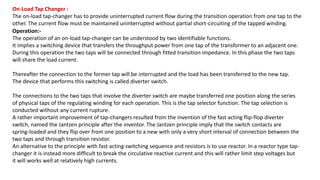
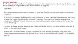
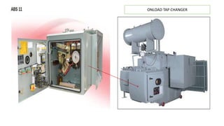
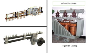
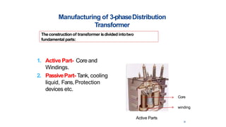
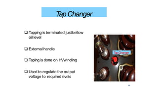
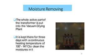
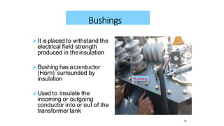
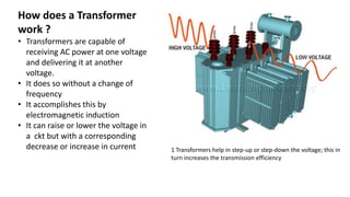
1. Transformers have on-load and off-load tap changers that allow adjusting the transformer's output voltage without interrupting the load current. On-load tap changers can adjust voltage while energized using fast-acting switches, while off-load tap changers require de-energizing the transformer to change taps.
2. On-load tap changers are commonly used in power generation and distribution transformers to control voltage as load and line conditions vary. They monitor voltage and raise or lower taps using an automatic voltage regulator. Off-load tap changers are typically used in solar and wind projects where the generator voltage is low-voltage.
3. The on-load tap changer maintains uninterrupted
![ON-LOAD & OFF-LOAD TAP CHANGER OF TRANSFORMER ( OLTC Vs OCTC )
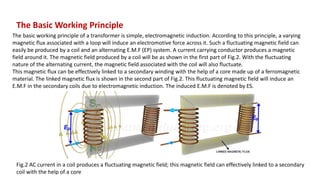
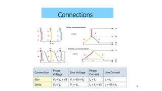
Power Generation, Transmission & Distribution Mainly on AC [Alternating Current]
System, Which is common in the World. So In Alternating Current System having
losses in the Generation as well as in Transmission.
When you are designing a building with high Demand power, then you need
permission to avail power from the Local EB. Meanwhile you have to install
Distribution Transformer to step-down the Voltage level from HT to LT, In Most
Common Voltage Distribution Class is 11 kV / 433 V
All LT Loads attains full Efficiency when LT System [i.e.433V] gets constant
voltage having Zero Voltage drop. This Scenario is possible only if HT Gets
Uniform Voltage level from the EB End. [i.e 11kV]. We known that
Transmission system having more losses due to the distance and amount of
common losses of AC System.So we difficult to achieve 11kV at HT End. So
the system which is co-ordinate with Grid to support to the Transformer to
achieve proper voltage level for the Distribution Purpose is Called as Tap
Change.](https://image.slidesharecdn.com/meppurchasetransformerppt-190810092720/85/Transformer-Detailed-Presentation-50-slids-17-320.jpg)
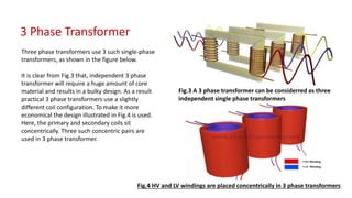
![Tap-changing
Transformers
The change of voltage is
affected by changing the
numbers of turns of the
transformer provided with
taps. For sufficiently close
control of voltage, taps are
usually provided on the high
voltage windings of the
transformer. There are two
types of tap-changing
transformers:
1. Off-load tap changer-
OCTC
2. On-load tap changer
OLTC
OFF-Load Tap Change: Mainly Used in Solar Power Project, Wind
Projects. Here Generating voltage level is LT at Conversion Level.[i.e
Inverter Level]Solar Inverter Duty oil type Transformer & Dry Type
Transformer having OFF-Load Tap Change. Concept.
Concept:
Tap Changing will happen While Transformer is in OFF-Load or No-
Load. In Dry Type Transformer, Cooling Phenomenon mainly Air
Natural. Normally In ON-Load Tap Changer, Arc Quenching will be
limited by medium of Oil When Transformer is ON-Load. But OFF-
Load Tap Changer, Tapping will be done only When Transformer is in
OFF-Switch Condition. In Dry Type Transformer Air is the only cooling
medium which is limited Energy to Arc Quench.
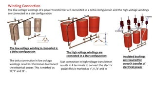
ON-Load Tap Change: Most of the Generating Station, Substation
system having Power Transformer with ON-Load Tap Changer. Not
only in Generating Station Transformer also in Distribution Class
Transformer too.
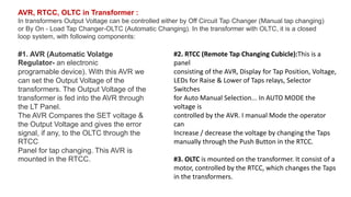
Concept
Tap Changing will happen While Transformer is in ON-Load. Tap
Changer System Monitors the Voltage level with the help of AVR
[Automatic Voltage Regulator]. AVR is in housed cubicle Called
RTCC Panel. It also houses Push button for Tap Riser & Lower,
Indicator for HT Voltage level, Heat Sensor etc., Most of the Oil
Impregnated Transformer having ON-Load Tap Changer Type.](https://image.slidesharecdn.com/meppurchasetransformerppt-190810092720/85/Transformer-Detailed-Presentation-50-slids-18-320.jpg)