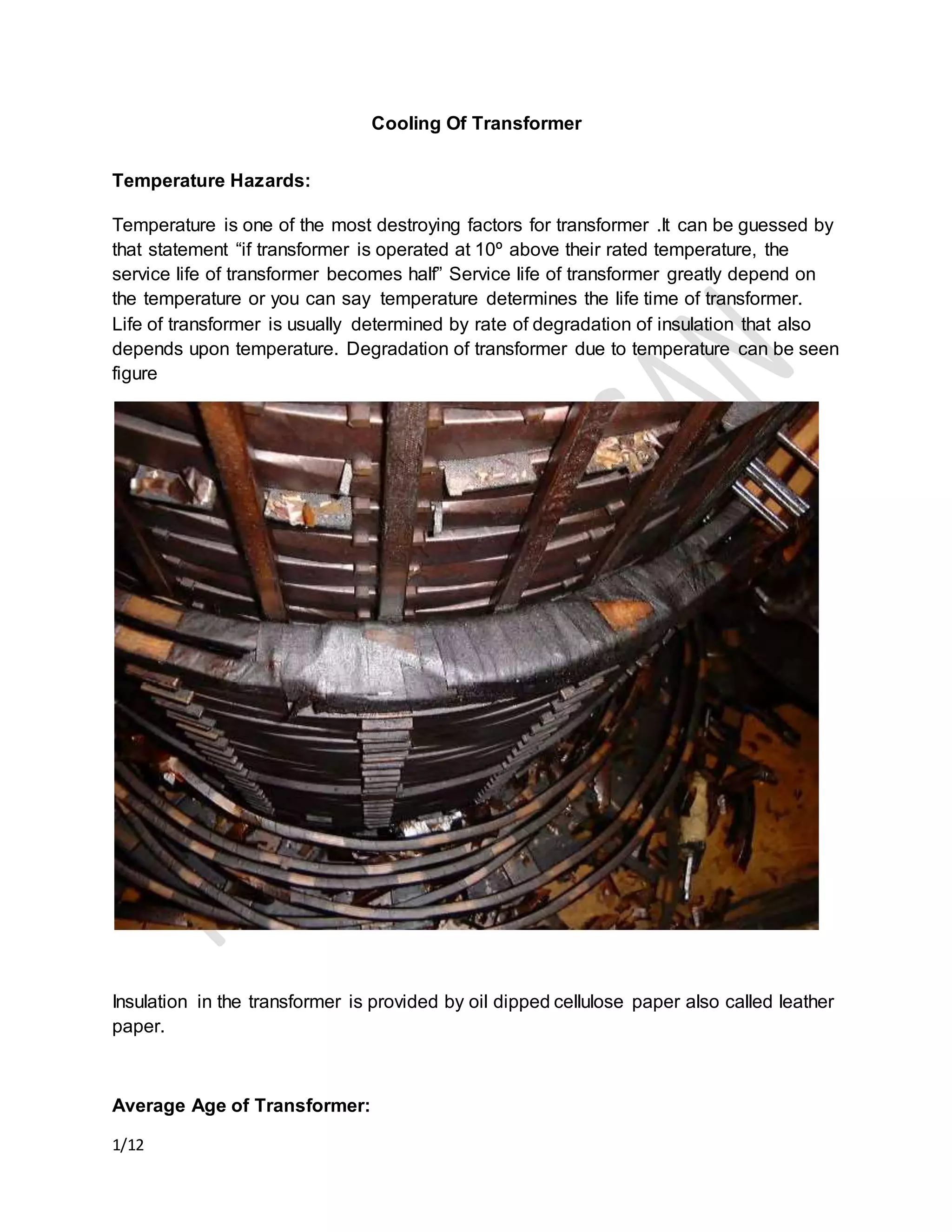
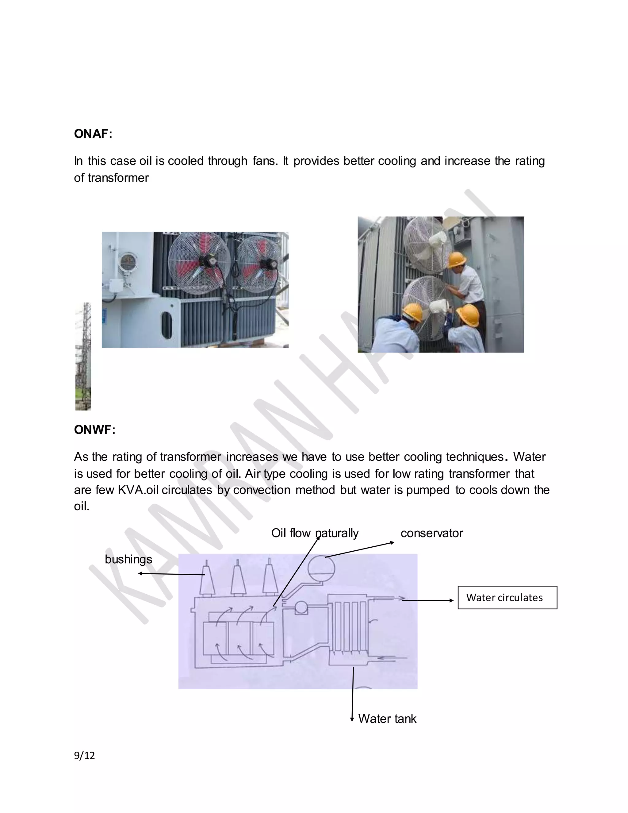
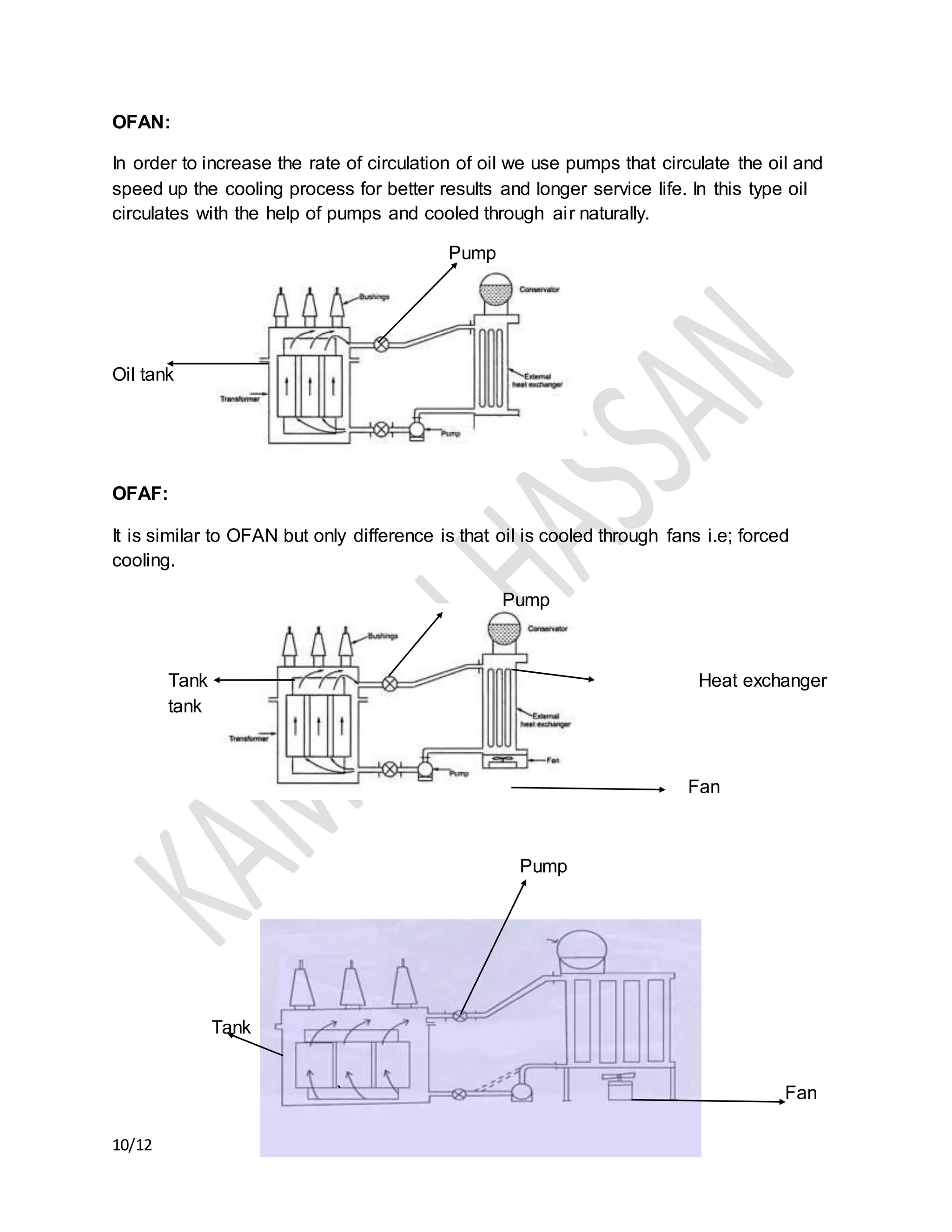
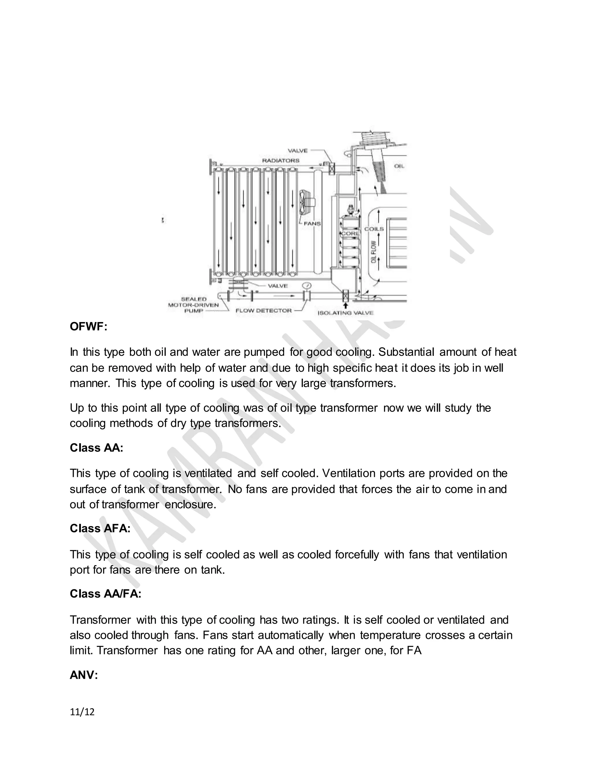
1/12
Cooling Of Transformer
Temperature Hazards:
Temperature is one of the most destroying factors for transformer .It can be guessed by
that statement “if transformer is operated at 10º above their rated temperature, the
service life of transformer becomes half” Service life of transformer greatly depend on
the temperature or you can say temperature determines the life time of transformer.
Life of transformer is usually determined by rate of degradation of insulation that also
depends upon temperature. Degradation of transformer due to temperature can be seen
figure
Insulation in the transformer is provided by oil dipped cellulose paper also called leather
paper.
Average Age of Transformer:
2/12
The average age of transformer is about 20 to 40 years for continuous operation at
rated load at ambient temperature of 40º and temperature rise of 65º .life time of
transformer may be more than this because it is operated at low temperature and well
below their rated load provided that their maintenance is done properly over the service
life of transformer
Aging Rate of Transformer:
The relative aging rate of transformer V is given as
𝑉 = 2(𝛩ℎ−98)/6
Withstand voltage of transformer decreases with the increase in moisture content in oil.
Temperature Classes of Transformer:
Insulation class A E B F H
Operating temperature 105ºC 120ºC 125ºC 145ºC 220ºC
Causes of High Temperature:
Temperature in transformer can be increased due to either external factors or due to
internal factors
Internal Factors:
 Over loading.
 Short circuit between transformer windings.
 Shortage of oil.
3/12
 Dust particles and other impurities in transformer.
External Factors:
 High surrounding temperature.
 External fault (Lightening wave on HT side).
Therefore cooling of transformers is very necessary. Some usually used methods of
transformer cooling are given below.
There are two types of cooling
 External cooling
 Internal cooling
Internal cooling means how the windings (inside the transformer tank) of transformer
are cooled. Internal cooling is usually done with oil. External cooling means how the oil
(that cools the winding) is cooled. It is usually cooled either by water or by air .Internal
and external cooling can be either natural (no pumps are used) or forced (pumps are
used).
Cooling Symbol:
 First symbol shows that internal cooling medium (inside tank) through which
windings are cooled
O indicates mineral oil or synthetic insulating liquid with fire point <300º
K indicates synthetic insulating liquid with fire point >300º
L indicates synthetic insulating liquid with no measureable fire point
 2nd symbol shows circulation mechanisim of internal medium ie; either cooled the
winding naturally or with force
N indicates natural convection flow through windings.
F indicates forced circulation through windings.
4/12
D indicates forced circulation and directed flow through windings
 3rd symbol shows that external cooling medium (outside tank) that cools the
internal cooling medium inside tank
A indicates air
W indicates water
 4th symbol shows the circulating mechanism of external medium i.e.; either
cooled the internal medium naturally or with force
N indicates natural convection
F indicates forced circulation
Symbols:
“O” indicates Oil
“A” indicates Air
“W” indicates Water
“N” indicates Natural
“F” indicates Forced
“D” indicates Directed
“ON” indicate Oil Natural
“AF” indicates Air Forced
“OF” indicates Oil Forced
“WF” indicates Water Forced
“OD” indicates Oil Directed
For example
5/12
 If winding is cooled with oil natural and oil is cooled with air naturally called
ONAN (oil natural air natural).
 If winding is cooled with oil naturally and oil is cooled with water pumps called
ONWF (oil natural water forced).
 If winding is cooled with oil naturally and oil is cooled with air pumps called
ONAF (oil natural air forced).
 If winding is cooled with oil pumps and oil is cooled with air naturally called
OFAN (oil forced air natural).
 If winding is cooled with oil pumps and oil is cooled with water pumps called
OFWF (oil forced water forced).
 If winding is cooled with oil pumps and oil is cooled with air pumps called OFAF
(oil forced air forced).
Internal cooling can also be categorized as
 Directed cooling or zig-zag cooling
 Non directed cooling or axial cooling
 Fully directed cooling or pumped cooling
All type of cooling can be explained through the following chat
6/12
Cooling of
Transformer
Air
Air Natural
ANAN
AA
ANV
Air Forced
AF
AFA
AA/FA
Gas
GA
Oil
Oil Natural
ONAN
ONAF
ONWF
Oil Forced
OFAN
OFWF
OFAF
Oil Directed or Zig-
Zag Cooling
ODAF
ODWF
ODAN
Non Oil
Directed
or Axial
Cooling
Fully
Directed or
Pumped
Cooling
Direct Cooling:
In this type of cooling oil circulates in the winding in zig-zag manner to keep the
temperature low as shown in figure.
7/12
Non Directed Cooling:
In this type oil flows in the winding axially.
Fully Pumped Cooling:
In this type oil is forced from radiator to flow through winding.
80% oil flow through windings
20% oil flow through core
Oil tank
8/12
Pumped Cooling
Fully pumped cooling with low rpm fan is used to minimize the cooling noise
ONAN:
Most of the transformers are ONAN cooled.oil is filled in transformer tank and oil is
cooled through air naturally. To increase the area of oil contact with air can be
increased by providing ribs or radiator or by tubes on the surface of tank. In case of
tubes oil warms up and follows through tubes where air cools down the oil and oil
moves into the tank and same cycle repeat again.
Tank
Circulating
oil
Tubes
9/12
ONAF:
In this case oil is cooled through fans. It provides better cooling and increase the rating
of transformer
ONWF:
As the rating of transformer increases we have to use better cooling techniques. Water
is used for better cooling of oil. Air type cooling is used for low rating transformer that
are few KVA.oil circulates by convection method but water is pumped to cools down the
oil.
Oil flow naturally conservator
bushings
Water tank
Water circulates
10/12
OFAN:
In order to increase the rate of circulation of oil we use pumps that circulate the oil and
speed up the cooling process for better results and longer service life. In this type oil
circulates with the help of pumps and cooled through air naturally.
Pump
Oil tank
OFAF:
It is similar to OFAN but only difference is that oil is cooled through fans i.e; forced
cooling.
Pump
Tank Heat exchanger
tank
Fan
Pump
Tank
` Fan
11/12
OFWF:
In this type both oil and water are pumped for good cooling. Substantial amount of heat
can be removed with help of water and due to high specific heat it does its job in well
manner. This type of cooling is used for very large transformers.
Up to this point all type of cooling was of oil type transformer now we will study the
cooling methods of dry type transformers.
Class AA:
This type of cooling is ventilated and self cooled. Ventilation ports are provided on the
surface of tank of transformer. No fans are provided that forces the air to come in and
out of transformer enclosure.
Class AFA:
This type of cooling is self cooled as well as cooled forcefully with fans that ventilation
port for fans are there on tank.
Class AA/FA:
Transformer with this type of cooling has two ratings. It is self cooled or ventilated and
also cooled through fans. Fans start automatically when temperature crosses a certain
limit. Transformer has one rating for AA and other, larger one, for FA
ANV:
12/12
this type of cooling is self cooled and non ventilated .no ventilation ports or fans are
provided . Transformer is cooled due to natural circulation around the enclosure of
transformer.
AG:
In this type gas is tightly enclosed in transformer tank and self cooled. Gas enclosed is
usually nitrogen to provide high dielectric strength and quick heat removal .transformer
is cooled by natural circulation of air around the enclosure of transformer.
13/12

Cooling Method of transformer

  • 1.
    1/12 Cooling Of Transformer TemperatureHazards: Temperature is one of the most destroying factors for transformer .It can be guessed by that statement “if transformer is operated at 10º above their rated temperature, the service life of transformer becomes half” Service life of transformer greatly depend on the temperature or you can say temperature determines the life time of transformer. Life of transformer is usually determined by rate of degradation of insulation that also depends upon temperature. Degradation of transformer due to temperature can be seen figure Insulation in the transformer is provided by oil dipped cellulose paper also called leather paper. Average Age of Transformer:
  • 2.
    2/12 The average ageof transformer is about 20 to 40 years for continuous operation at rated load at ambient temperature of 40º and temperature rise of 65º .life time of transformer may be more than this because it is operated at low temperature and well below their rated load provided that their maintenance is done properly over the service life of transformer Aging Rate of Transformer: The relative aging rate of transformer V is given as 𝑉 = 2(𝛩ℎ−98)/6 Withstand voltage of transformer decreases with the increase in moisture content in oil. Temperature Classes of Transformer: Insulation class A E B F H Operating temperature 105ºC 120ºC 125ºC 145ºC 220ºC Causes of High Temperature: Temperature in transformer can be increased due to either external factors or due to internal factors Internal Factors:  Over loading.  Short circuit between transformer windings.  Shortage of oil.
  • 3.
    3/12  Dust particlesand other impurities in transformer. External Factors:  High surrounding temperature.  External fault (Lightening wave on HT side). Therefore cooling of transformers is very necessary. Some usually used methods of transformer cooling are given below. There are two types of cooling  External cooling  Internal cooling Internal cooling means how the windings (inside the transformer tank) of transformer are cooled. Internal cooling is usually done with oil. External cooling means how the oil (that cools the winding) is cooled. It is usually cooled either by water or by air .Internal and external cooling can be either natural (no pumps are used) or forced (pumps are used). Cooling Symbol:  First symbol shows that internal cooling medium (inside tank) through which windings are cooled O indicates mineral oil or synthetic insulating liquid with fire point <300º K indicates synthetic insulating liquid with fire point >300º L indicates synthetic insulating liquid with no measureable fire point  2nd symbol shows circulation mechanisim of internal medium ie; either cooled the winding naturally or with force N indicates natural convection flow through windings. F indicates forced circulation through windings.
  • 4.
    4/12 D indicates forcedcirculation and directed flow through windings  3rd symbol shows that external cooling medium (outside tank) that cools the internal cooling medium inside tank A indicates air W indicates water  4th symbol shows the circulating mechanism of external medium i.e.; either cooled the internal medium naturally or with force N indicates natural convection F indicates forced circulation Symbols: “O” indicates Oil “A” indicates Air “W” indicates Water “N” indicates Natural “F” indicates Forced “D” indicates Directed “ON” indicate Oil Natural “AF” indicates Air Forced “OF” indicates Oil Forced “WF” indicates Water Forced “OD” indicates Oil Directed For example
  • 5.
    5/12  If windingis cooled with oil natural and oil is cooled with air naturally called ONAN (oil natural air natural).  If winding is cooled with oil naturally and oil is cooled with water pumps called ONWF (oil natural water forced).  If winding is cooled with oil naturally and oil is cooled with air pumps called ONAF (oil natural air forced).  If winding is cooled with oil pumps and oil is cooled with air naturally called OFAN (oil forced air natural).  If winding is cooled with oil pumps and oil is cooled with water pumps called OFWF (oil forced water forced).  If winding is cooled with oil pumps and oil is cooled with air pumps called OFAF (oil forced air forced). Internal cooling can also be categorized as  Directed cooling or zig-zag cooling  Non directed cooling or axial cooling  Fully directed cooling or pumped cooling All type of cooling can be explained through the following chat
  • 6.
    6/12 Cooling of Transformer Air Air Natural ANAN AA ANV AirForced AF AFA AA/FA Gas GA Oil Oil Natural ONAN ONAF ONWF Oil Forced OFAN OFWF OFAF Oil Directed or Zig- Zag Cooling ODAF ODWF ODAN Non Oil Directed or Axial Cooling Fully Directed or Pumped Cooling Direct Cooling: In this type of cooling oil circulates in the winding in zig-zag manner to keep the temperature low as shown in figure.
  • 7.
    7/12 Non Directed Cooling: Inthis type oil flows in the winding axially. Fully Pumped Cooling: In this type oil is forced from radiator to flow through winding. 80% oil flow through windings 20% oil flow through core Oil tank
  • 8.
    8/12 Pumped Cooling Fully pumpedcooling with low rpm fan is used to minimize the cooling noise ONAN: Most of the transformers are ONAN cooled.oil is filled in transformer tank and oil is cooled through air naturally. To increase the area of oil contact with air can be increased by providing ribs or radiator or by tubes on the surface of tank. In case of tubes oil warms up and follows through tubes where air cools down the oil and oil moves into the tank and same cycle repeat again. Tank Circulating oil Tubes
  • 9.
    9/12 ONAF: In this caseoil is cooled through fans. It provides better cooling and increase the rating of transformer ONWF: As the rating of transformer increases we have to use better cooling techniques. Water is used for better cooling of oil. Air type cooling is used for low rating transformer that are few KVA.oil circulates by convection method but water is pumped to cools down the oil. Oil flow naturally conservator bushings Water tank Water circulates
  • 10.
    10/12 OFAN: In order toincrease the rate of circulation of oil we use pumps that circulate the oil and speed up the cooling process for better results and longer service life. In this type oil circulates with the help of pumps and cooled through air naturally. Pump Oil tank OFAF: It is similar to OFAN but only difference is that oil is cooled through fans i.e; forced cooling. Pump Tank Heat exchanger tank Fan Pump Tank ` Fan
  • 11.
    11/12 OFWF: In this typeboth oil and water are pumped for good cooling. Substantial amount of heat can be removed with help of water and due to high specific heat it does its job in well manner. This type of cooling is used for very large transformers. Up to this point all type of cooling was of oil type transformer now we will study the cooling methods of dry type transformers. Class AA: This type of cooling is ventilated and self cooled. Ventilation ports are provided on the surface of tank of transformer. No fans are provided that forces the air to come in and out of transformer enclosure. Class AFA: This type of cooling is self cooled as well as cooled forcefully with fans that ventilation port for fans are there on tank. Class AA/FA: Transformer with this type of cooling has two ratings. It is self cooled or ventilated and also cooled through fans. Fans start automatically when temperature crosses a certain limit. Transformer has one rating for AA and other, larger one, for FA ANV:
  • 12.
    12/12 this type ofcooling is self cooled and non ventilated .no ventilation ports or fans are provided . Transformer is cooled due to natural circulation around the enclosure of transformer. AG: In this type gas is tightly enclosed in transformer tank and self cooled. Gas enclosed is usually nitrogen to provide high dielectric strength and quick heat removal .transformer is cooled by natural circulation of air around the enclosure of transformer.
  • 13.