Download as ODP, PPTX


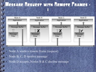

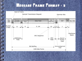

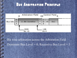


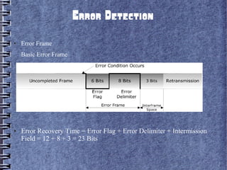


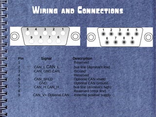


Controller Area Network (CAN) is a serial bus standard used for vehicle communication and industrial automation. It allows microcontrollers and devices to communicate with each other in applications that require high reliability. CAN was developed by Bosch as a multi-master broadcast system that can transmit short messages up to 1 megabit per second. Nodes on the CAN bus can broadcast short messages, such as sensor data, to all other nodes to ensure consistent data across the network. CAN uses priority-based arbitration to resolve conflicts when multiple nodes attempt to transmit simultaneously. It has excellent error detection capabilities to maintain reliability. CAN has become popular for vehicle networks and industrial applications requiring real-time communication between embedded systems.