Downloaded 276 times

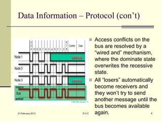
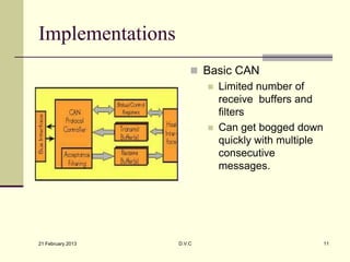
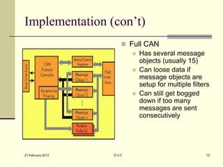
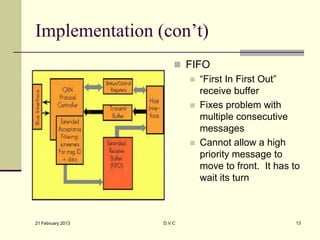
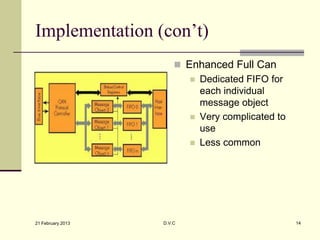
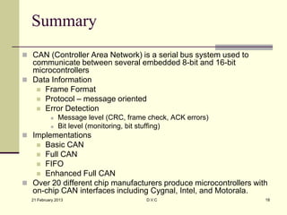

CAN (Controller Area Network) is a serial bus system used to communicate between embedded microcontrollers. It uses a message-oriented transmission protocol with prioritized messages identified by unique identifiers. Error detection occurs at both the message level, through CRC and ACK errors, and bit level, via monitoring and bit stuffing. Implementations include Basic CAN, Full CAN, FIFO, and Enhanced Full CAN. Over 20 manufacturers produce microcontrollers with CAN interfaces, such as Cygnal, Intel, and Motorola.