Download as PDF, PPTX

![ Controlled area network: CAN properties
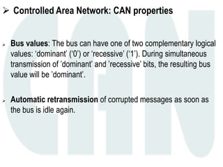
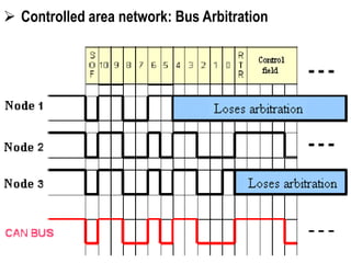
Multi master: When the bus is free any unit may start to transmit
a message.
If two nodes need to transmit in the same time, the unit with the
message of higher priority to be transmitted gains bus access.
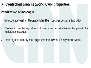
Message Routing: An identifier names the content of a message.
The identifier does not indicate the destination of the message,
but describes the meaning of the data, so that all nodes in the
network are able to decide by message filtering whether the data
is to be acted upon by them or not [publish /subscribe].](https://image.slidesharecdn.com/automotivebustechnologies-161024105921/85/Automotive-bus-technologies-50-320.jpg)
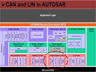

The document provides an overview of automotive embedded systems and network technologies. It discusses electronic control units (ECUs) and their functions. Two main automotive bus protocols are described: Local Interconnect Network (LIN) and Controller Area Network (CAN). LIN uses a single wire connection and supports speeds up to 20kbps, while CAN uses a two-wire connection and supports speeds up to 1Mbps. The document outlines the frame structures, message types, and error handling approaches for both LIN and CAN networks.