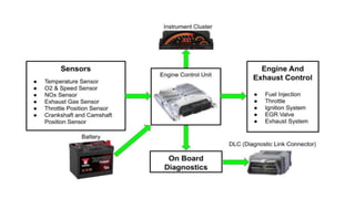
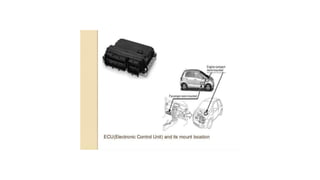
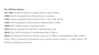
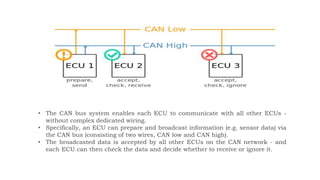
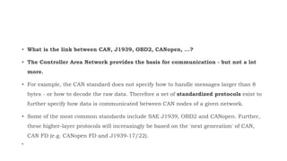
2. Electronic Control Unit (ECU)
Electronic Control Unit (ECU) is a small device inside a vehicle that
controls one or several electrical systems in the vehicle It tells
electrical systems what to do and how to do and when to do. ECU‟s
core is a microcontroller and it is controlled by embedded software.
3.
4.
5. The CAN bus history :
•Pre CAN: Car ECUs relied on complex point-to-point wiring
•1986: Bosch developed the CAN protocol as a solution
•1991: Bosch published CAN 2.0 (CAN 2.0A: 11 bit, 2.0B: 29 bit)
•1993: CAN is adopted as international standard (ISO 11898)
•2003: ISO 11898 becomes a standard series
•2012: Bosch released the CAN FD 1.0 (flexible data rate)
•2015: The CAN FD protocol is standardized (ISO 11898-1)
•2016: The physical CAN layer for data-rates up to 5 Mbit/s standardized in ISO 11898-2
Today, CAN is standard in automotives (cars, trucks, buses, tractors, ...), ships, planes, EV
batteries, machinery and more
6. The future of CAN bus
Looking ahead, the CAN bus protocol will stay relevant - though it will be impacted by major
trends:
•A need for increasingly advanced vehicle functionality
•The rise of cloud computing
•Growth in Internet of Things (IoT) and connected vehicles
•The impact of autonomous vehicles
In particular, the rise in connected vehicles (V2X) and cloud will lead to a rapid growth in vehicle
telematics and IoT CAN loggers.
In turn, bringing the CAN bus network 'online' also exposes vehicles to security risks - and may
require a shift to new CAN protocols like CAN FD.
7. As vehicle functionality expands, so does the load on the CANbus. To support this, CAN
FD (Flexible Data Rate) has been designed as the 'next generation' CAN bus.
Specifically, CAN FD offers three benefits (vs Classical CAN):
•It enables data rates up to 8 Mbit/s (vs 1 Mbit/s)
•It allows data payloads of up to 64 bytes (vs 8 bytes)
•It enables improved security via authentication
In short, CAN FD boosts speed and efficiency - and it is therefore being rolled out in newer vehicles.
This will also drive an increasing need for IoT CAN FD data loggers.
8. • The Controller Area Network (CAN bus) is the nervous system which enables
communication. In turn, „electronic control units' (ECUs) are like parts of the body,
interconnected via the CAN bus.
• Information sensed by one part can be shared with another.
• In an automotive CAN bus system, ECUs can control airbags, audio system.
• A modern car may have up to 70 ECUs - and each of them may have information that
needs to be shared with other parts of the network.
• The data in a frame is transmitted sequentially but if more than one device transmit at
same time, the highest priority device can continue while the others back off.
Controller Area Network
9. • The CAN bus system enables each ECU to communicate with all other ECUs -
without complex dedicated wiring.
• Specifically, an ECU can prepare and broadcast information (e.g. sensor data) via
the CAN bus (consisting of two wires, CAN low and CAN high).
• The broadcasted data is accepted by all other ECUs on the CAN network - and
each ECU can then check the data and decide whether to receive or ignore it.
10. The CAN bus physical layer defines things like cable types, electrical signal levels, node requirements,
cable impedance etc.
For example, ISO 11898-2 dictates a number of things, including below:
•Baud rate: CAN nodes must be connected via a two wire bus with baud rates up to
•1 Mbit/s (Classical CAN) or 5 Mbit/s
•Cable length: Maximal CAN cable lengths should be between 500 meters (125 kbit/s) and
40 meters (1 Mbit/s)
•Termination: The CAN bus must be properly terminated using a 120 Ohms CAN bus termination
resistor at each end of the bus
11. •High speed CAN bus: The focus of this article is on high speed CAN bus (ISO 11898). It is
by far the most popular CAN standard for the physical layer, supporting bit rates from 40
kbit/s to 1 Mbit/s (Classical CAN). It provides simple cabling and is used in practically all
automotive applications today. It also serves as the basis for several higher layer protocols
such as OBD2, J1939, NMEA 2000, CANopen etc. The second generation of CAN is referred
to as CAN FD (CAN with Flexible Data-rate)
•Low speed CAN bus: This standard enables bit rates from 40 kbit/s to 125 kbit/s and
allows the CAN bus commmunication to continue even if there is a fault on one of the two
wires - hence it is also referred to as 'fault tolerant CAN'. In this system, each CAN node
has it's own CAN termination
•LIN bus: LIN bus is a lower cost supplement to CAN bus networks, with less harness and
cheaper nodes. LIN bus clusters typically consist of a LIN master acting as gateway and up
to 16 slave nodes. Typical use cases include e.g. non-critical vehicle functions like
aircondition, door functionality etc. - for details see our LIN bus intro or LIN bus data
logger article
12. 4 benefits of CAN bus
• Simple & low cost
ECUs communicate via a single CAN system instead of via direct
complex analogue signal lines - reducing errors, weight, wiring and
costs
13. • Fully centralized
• The CAN bus provides 'one point-of-entry' to communicate with all
network ECUs - enabling central diagnostics, data logging and
configuration
14. • Extremely robust
• The system is robust towards electric disturbances and
electromagnetic interference - ideal for safety critical applications
(e.g. vehicles)
15. • Efficient
• CAN frames are prioritized by ID so that top priority data gets
immediate bus access, without causing interruption of other
frames
16. What is a CAN frame?
Communication over the CAN bus is done via CAN frames.
Below is a standard CAN frame with 11 bits identifier (CAN 2.0A), which is the type used
in most cars. The extended 29-bit identifier frame (CAN 2.0B) is identical except the
longer ID. It is e.g. used in the J1939 protocol for heavy-duty vehicles.
Note that the CAN ID and Data are highlighted - these are important when recording CAN
bus data
19. How to log CAN bus data
• Two CAN fields are important for CAN logging:
The CAN ID and the Data.
• To record CAN data you need a CAN logger. This lets you log
timestamped CAN data to an SD card. In some cases, you need
a CAN interface to stream data to a PC - e.g. for car hacking.
20.
21. How does OBD2 data logging work?
To log OBD2 data involves 3 simple steps:
1.Configure your OBD2 logger with a list of OBD2 PIDs
2.Connect it in your car via an OBD2 adapter to start logging
3.Extract the SD and decode the data via the free software/API
24. • What is the link between CAN, J1939, OBD2, CANopen, ...?
• The Controller Area Network provides the basis for communication - but not a lot
more.
• For example, the CAN standard does not specify how to handle messages larger than 8
bytes - or how to decode the raw data. Therefore a set of standardized protocols exist to
further specify how data is communicated between CAN nodes of a given network.
• Some of the most common standards include SAE J1939, OBD2 and CANopen. Further,
these higher-layer protocols will increasingly be based on the 'next generation' of CAN,
CAN FD (e.g. CANopen FD and J1939-17/22).
•
25. How to log CAN bus data
• This first step is to connect your CAN logger to your CAN bus. Typically this involves
using an adapter cable:
• Cars: In most cars, you simply use an OBD2 adapter to connect. In most cars, this will let
you log raw CAN data, as well as perform OBD2/UDS requests to log OBD2/UDS data
• When you've identified the right connector and verified the pin-out, you can connect your
CAN logger to start recording data. For the CANedge/CLX000, the CAN baud rate is auto-
detected and the device will start logging raw CAN data immediately.
26.
27.
28. What is OBD2?
• OBD2 is your vehicle's built-in self-diagnostic system.
• You've probably encountered OBD2 already:
• Ever noticed the malfunction indicator light on your
dashboard?
• That is your car telling you there is an issue. If you visit a
mechanic, he will use an OBD2 scanner to diagnose the
issue.
• To do so, he will connect the OBD2 reader to the OBD2 16 pin
connector near the steering wheel.
• This lets him read OBD2 codes aka Diagnostic Trouble Codes
(DTCs) to review and troubleshoot the issue.
29. The OBD2 connector
• The OBD2 connector lets you access data from your car easily. The
standard SAE J1962 specifies two female OBD2 16-pin connector types
(A & B).
• In the illustration is an example of a Type A OBD2 pin connector (also
sometimes referred to as the Data Link Connector, DLC).
• A few things to note:
• The OBD2 connector is near your steering wheel, but may be hidden
behind covers/panels
• Not all male connectors fit all OBD2 female sockets - check the type and
OBD port pin-outs
• Pin 16 supplies power via the car battery - often also while the ignition is
off
• Pins 6 (CAN-H) and 14 (CAN-L) are most relevant as CAN (ISO 15765-4) is
standard in most modern cars (incl. EVs)
30. The CAN Bus
• What is CAN?
CAN is short for ‘controller area network’. Controller area network
is an electronic communication bus defined by the ISO 11898
standards. Those standards define how communication happens,
how wiring is configured and how messages are constructed,
among other things. Collectively, this system is referred to as a
CAN bus.
31. CAN Messages
The CAN bus is a broadcast type of bus. This means that
all nodes can ‘hear’ all transmissions. There is no way to
send a message to just a specific node; all nodes will
invariably pick up all traffic. The CAN hardware, however,
provides local filtering so that each node may react only
on the interesting messages.
The CAN messages
CAN uses short messages – the maximum utility load is
94 bits. There is no explicit address in the messages;
instead, the messages can be said to be contents-
addressed, that is, their contents implicitly determines
their address.
32. Message Types
There are four different message types (or ‘frames’) on a
CAN bus:
1.the Data Frame
2.the Remote Frame
3.the Error Frame
4.the Overload Frame