Download to read offline
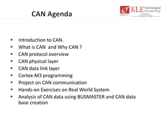
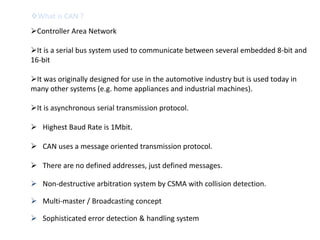
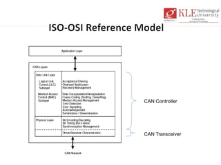
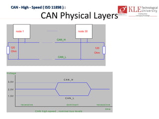
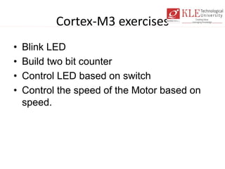
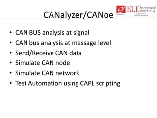

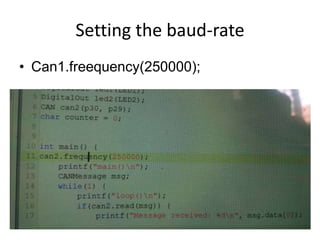
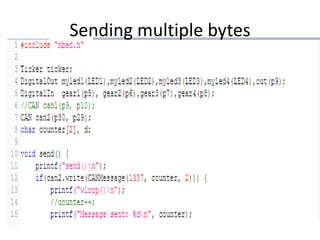

The document provides an overview of Controller Area Network (CAN) network development. It discusses CAN protocol fundamentals including layers, frames, error handling, and physical implementation. It also outlines hands-on exercises for CAN programming on Cortex-M3 boards, sending data over CAN networks, and analyzing CAN traffic using tools like CANalyzer and BUSMASTER.


![20260201 [FOSDEM] gomodjail - library sandboxing for Go modules.pdf](https://cdn.slidesharecdn.com/ss_thumbnails/20260201fosdemgomodjail-librarysandboxingforgomodules-260201225659-76609ec4-thumbnail.jpg?width=640&height=640&fit=bounds)

