Downloaded 47 times

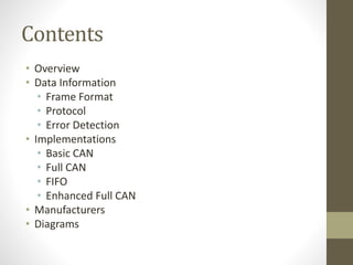
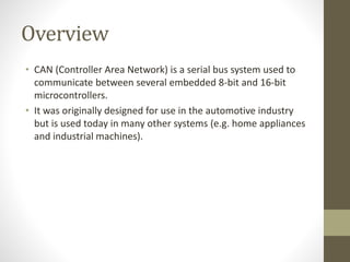


CAN (Controller Area Network) is a serial bus system used for communication between microcontrollers. It uses a message-oriented protocol where messages are distinguished by identifiers and priority is determined by identifier value. The frame format includes start of frame, identifier, data length code, CRC, and other fields. Error detection occurs at the message level using CRC and frame checks and at the bit level through monitoring and bit stuffing. Implementations include Basic CAN, Full CAN, FIFO, and Enhanced Full CAN. Over 20 manufacturers produce microcontrollers with CAN interfaces.