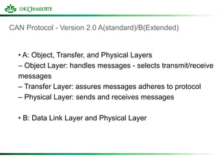
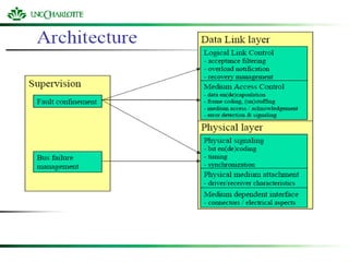
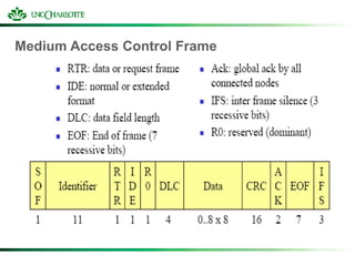
ECGR 6185
Advanced Embedded Systems
Controller Area Network
University Of North Carolina Charlotte
Bipin Suryadevara
Intra-vehicular communication
• A typical vehicle has a large number of electronic control
systems
• Some of such control systems
– Engine timing
– Gearbox and carburetor throttle control
– Anti-block systems (ABS)
– Acceleration skid control (ASC)
• The growth of automotive electronics is a result of:
– Customers wish for better comfort and better safety.
– Government requirements for improved emission control
– Reduced fuel consumption
How do we connect these control devices?
• With conventional systems, data is exchanged by means of
dedicated signal lines.
• But this is becoming increasingly difficult and expensive as
control functions become ever more complex.
• In case of complex control systems in particular, the number of
connections cannot be increased much further.
Solution: Use Fieldbus networks for connecting the control devices
What Fieldbus Networks are currently on the market?
some of the Fieldbus technologies currently on the market
– RS-232
– RS-485
– CAN ( we will discuss in detail)
– ARCNET
– IEC 1158-2
– BITBUS (IEEE 1118)
– ModBus
– HART
– Conitel
– DF1
– Data Highway [+]
Controller Area Network (CAN)
Controller Area Network (CAN) is a fast serial bus that is designed
to provide
– an efficient,
– Reliable and
– Very economical link between sensors and actuators.
CAN uses a twisted pair cable to communicate at speeds up to
1Mbit/s with up to 40 devices.
Originally developed to simplify the wiring in automobiles.
CAN fieldbuses are now used in machine and factory automation
products as well.
CAN features
• Any node can access the bus when the bus is quiet
• Non-destructive bit-wise arbitration to allow 100% use of the
bandwidth without loss of data
• Variable message priority based on 11-bit (or 29 bit) packet
identifier
• Peer-to-peer and multi-cast reception
• Automatic error detection, signaling and retries
• Data packets are 8 bytes long
Tradeoff: CAN bus versus point-to-point connections
• By introducing one single bus as the only means of
communication as opposed to the point-to-point network, we
traded off the channel access simplicity for the circuit simplicty
• Since two devices might want to transmit simultaneously, we
need to have a MAC protocol to handle the situation.
• CAN manages MAC issues by using a unique identifier for each
of the outgoing messages
• Identifier of a message represents its priority.
Physical CAN connection
CAN
CAN BUS
CS1 CS2 CS3 CS4 CS5
CAN Station 1 CAN Station 5
CAN Protocol - Version 2.0 A(standard)/B(Extended)
• A: Object, Transfer, and Physical Layers
– Object Layer: handles messages - selects transmit/receive
messages
– Transfer Layer: assures messages adheres to protocol
– Physical Layer: sends and receives messages
• B: Data Link Layer and Physical Layer
Physical Layer
• Topology
- Terminated bus
• Number of stations
-In principle limited to 30 (depends on drivers)
• Medium
- Twisted pair, single wire
• Range
-Signaling speed and propagation speed dependent: 40m at 1Mbit/s
-Drop length limited to 30 cm
• Signaling and bit encoding
-10 kbit/s to 1 Mbit/s, NRZ
Physical Layer
• Synchronization
- Uses signal edges (implies bit stuffing with NRZ)
- After Five consecutive ones, a zero is inserted
- After Five consecutive zeros, a one is inserted
-This rules includes a possible stuffing bit inserted before
• Signals
- Recessive: logical “1”
- Dominant: logical “0”
- When two stations compete on a bit by bit basis, the station that
emits dominant bit imposes this level on the bus
Medium Access Control Frame
Extended Addressing
Addressing
• Single 11 or 29 bit identifier per frame
– If used to identify a node
• Source(data) or Destination(request) of the message
– Normally used to identify the payload
– A lower value gives higher value in contention,
Error Detection
Several means
• Bit error
– When what is one the bus is different from what was emitted
• Except when a recessive bit was emitted during arbitration or
ack slot
• Cyclic Redundancy Check (CRC)
• Frame check (the frame structure is checked)
• ACK errors (absence of a dominant bit during the ack slot)
• Monitoring (each node which transmits also observes the
bus level and thus detects differences between the bit sent
and the bit received).
Error Detection
• Bit stuffing (checking adherence to the stuffing rule.)
• A frame is valid for
– A transmitter if there is no error until the end of EOF
– A receiver if there is no error until the next to last bit of
EOF
Behavior in case of error
• In case of stuff, bit, form or acknowledge errors
– An error flag is started at the next bit
• In case of CRC error
– An error frame is send after the ack delimiter
• Fault confinement
– Each time an reception error occurs, REC is incremented
– Each time a frame is received correctly, REC is decremented
– Same for the emission errors with TEC
– The values of TEC and REC may trigger mode changes
Connection Modes
To enforce fault confinement, nodes may be in one of
three modes
• Error active
– Normally takes part to the communication and may send an
active error flag (six dominant consecutive bits) when an
error has been detected.
• Error passive
– Takes part in communication but must not send an active
error flag. Instead, it shall send a passive error flag (six
recessive consecutive bits)
– Some restrictions (silence between two tx).
Connection Modes
• Bus off
– Cannot send or receive any frame.
– A node is in this state when it is switched of the bus due to a
request from a fault confinement entity. May exit from this
state only by a user command
Error Frame
• Two fields: Error flag and Error delimiter
• Error flag
– Active: Six dominant bits
– Passive: Six recessive bits
– As all nodes monitor the bus and the flag violates stuffing
rules, they will send error flags too
• The error flag will last from 6 to 12 bits
Error Frame
• Error delimiter (Eight recessive bits)
– After sending an error flag, a node shall send recessive bits
– As soon as it senses a recessive bit, it sends seven
recessive bits
Error Recovery
• Automatic retransmission
– Of all frames that have lost arbitration
– Of all frames have been disturbed by errors during
transmission
Medium Access Control
• All messages are sent in broadcast
• Nodes filter according to their interest
• All messages are acknowledged including by nodes that
are not interested by the message
– Acknowledge just means “message well received by all
receivers”
• It does not mean “intended receiver received it”
Medium Access Control
• Node that does not receive message correctly sends an
error bit sequence
• Node that is too busy may send an overload bit seq.
– MA_OVLD.request/indication/confirm
– Same principle as an error
Logical Link Control
• Two types of services (connectionless)
– Send Data with no ack
• L_DATA.request, L_DATA.indication, L_DATA.confirm
• Uses a data frame
– Request Data
• L_REMOTE.request,L_REMOTE.indication,L_REMOTE.confir
m
• Uses a remote frame (same as a data frame but data field is
empty)
– Flow control using the overload bit sequence
Implicit collision handling in the CAN bus
• If two messages are simultaneously sent over the CAN bus, the
bus takes the “logical AND” of all them
• Hence, the messages identifiers with the lowest binary number
gets the highest priority
• Every device listens on the channel and backs off as and when
it notices a mismatch between the bus’s bit and its identifier’s bit
Implicit collision handling in the CAN bus: example
Node B’s
message-ID
0
0 0 0 0 0
0 0 0 0 0
1 1 1
1 1 1 1
0
1
0 0
Node A’s
message-ID
BUS
0 0 0
1 1
Node B notices a mismatch
in bit # 3 on the bus.
Therefore, it stops
transmitting thereafter
Unlike the MAC protocols we learnt, in CAN a collision does not result in
wastage of bandwidth.
Hence, CAN achieves 100% bandwidth utilization
References
http://www.fieldbus.com.au/techinfo.htm#Top
http://www.esd-electronics.com/german/PDF-file/CAN/Englisch/intro-e.pdf
http://www.eng.man.ac.uk/mech/merg/FieldbusTeam/Fieldbus%20Introduction.htm#_Toc487265349
THANKYOU
QUESTIONS?????????

CAN.ppt

  • 1.
    ECGR 6185 Advanced EmbeddedSystems Controller Area Network University Of North Carolina Charlotte Bipin Suryadevara
  • 2.
    Intra-vehicular communication • Atypical vehicle has a large number of electronic control systems • Some of such control systems – Engine timing – Gearbox and carburetor throttle control – Anti-block systems (ABS) – Acceleration skid control (ASC) • The growth of automotive electronics is a result of: – Customers wish for better comfort and better safety. – Government requirements for improved emission control – Reduced fuel consumption
  • 3.
    How do weconnect these control devices? • With conventional systems, data is exchanged by means of dedicated signal lines. • But this is becoming increasingly difficult and expensive as control functions become ever more complex. • In case of complex control systems in particular, the number of connections cannot be increased much further. Solution: Use Fieldbus networks for connecting the control devices
  • 4.
    What Fieldbus Networksare currently on the market? some of the Fieldbus technologies currently on the market – RS-232 – RS-485 – CAN ( we will discuss in detail) – ARCNET – IEC 1158-2 – BITBUS (IEEE 1118) – ModBus – HART – Conitel – DF1 – Data Highway [+]
  • 5.
    Controller Area Network(CAN) Controller Area Network (CAN) is a fast serial bus that is designed to provide – an efficient, – Reliable and – Very economical link between sensors and actuators. CAN uses a twisted pair cable to communicate at speeds up to 1Mbit/s with up to 40 devices. Originally developed to simplify the wiring in automobiles. CAN fieldbuses are now used in machine and factory automation products as well.
  • 6.
    CAN features • Anynode can access the bus when the bus is quiet • Non-destructive bit-wise arbitration to allow 100% use of the bandwidth without loss of data • Variable message priority based on 11-bit (or 29 bit) packet identifier • Peer-to-peer and multi-cast reception • Automatic error detection, signaling and retries • Data packets are 8 bytes long
  • 7.
    Tradeoff: CAN busversus point-to-point connections • By introducing one single bus as the only means of communication as opposed to the point-to-point network, we traded off the channel access simplicity for the circuit simplicty • Since two devices might want to transmit simultaneously, we need to have a MAC protocol to handle the situation. • CAN manages MAC issues by using a unique identifier for each of the outgoing messages • Identifier of a message represents its priority.
  • 8.
  • 9.
    CAN CAN BUS CS1 CS2CS3 CS4 CS5 CAN Station 1 CAN Station 5
  • 10.
    CAN Protocol -Version 2.0 A(standard)/B(Extended) • A: Object, Transfer, and Physical Layers – Object Layer: handles messages - selects transmit/receive messages – Transfer Layer: assures messages adheres to protocol – Physical Layer: sends and receives messages • B: Data Link Layer and Physical Layer
  • 12.
    Physical Layer • Topology -Terminated bus • Number of stations -In principle limited to 30 (depends on drivers) • Medium - Twisted pair, single wire • Range -Signaling speed and propagation speed dependent: 40m at 1Mbit/s -Drop length limited to 30 cm • Signaling and bit encoding -10 kbit/s to 1 Mbit/s, NRZ
  • 13.
    Physical Layer • Synchronization -Uses signal edges (implies bit stuffing with NRZ) - After Five consecutive ones, a zero is inserted - After Five consecutive zeros, a one is inserted -This rules includes a possible stuffing bit inserted before • Signals - Recessive: logical “1” - Dominant: logical “0” - When two stations compete on a bit by bit basis, the station that emits dominant bit imposes this level on the bus
  • 14.
  • 15.
  • 16.
    Addressing • Single 11or 29 bit identifier per frame – If used to identify a node • Source(data) or Destination(request) of the message – Normally used to identify the payload – A lower value gives higher value in contention,
  • 17.
    Error Detection Several means •Bit error – When what is one the bus is different from what was emitted • Except when a recessive bit was emitted during arbitration or ack slot • Cyclic Redundancy Check (CRC) • Frame check (the frame structure is checked) • ACK errors (absence of a dominant bit during the ack slot) • Monitoring (each node which transmits also observes the bus level and thus detects differences between the bit sent and the bit received).
  • 18.
    Error Detection • Bitstuffing (checking adherence to the stuffing rule.) • A frame is valid for – A transmitter if there is no error until the end of EOF – A receiver if there is no error until the next to last bit of EOF
  • 19.
    Behavior in caseof error • In case of stuff, bit, form or acknowledge errors – An error flag is started at the next bit • In case of CRC error – An error frame is send after the ack delimiter • Fault confinement – Each time an reception error occurs, REC is incremented – Each time a frame is received correctly, REC is decremented – Same for the emission errors with TEC – The values of TEC and REC may trigger mode changes
  • 20.
    Connection Modes To enforcefault confinement, nodes may be in one of three modes • Error active – Normally takes part to the communication and may send an active error flag (six dominant consecutive bits) when an error has been detected. • Error passive – Takes part in communication but must not send an active error flag. Instead, it shall send a passive error flag (six recessive consecutive bits) – Some restrictions (silence between two tx).
  • 21.
    Connection Modes • Busoff – Cannot send or receive any frame. – A node is in this state when it is switched of the bus due to a request from a fault confinement entity. May exit from this state only by a user command
  • 22.
    Error Frame • Twofields: Error flag and Error delimiter • Error flag – Active: Six dominant bits – Passive: Six recessive bits – As all nodes monitor the bus and the flag violates stuffing rules, they will send error flags too • The error flag will last from 6 to 12 bits
  • 23.
    Error Frame • Errordelimiter (Eight recessive bits) – After sending an error flag, a node shall send recessive bits – As soon as it senses a recessive bit, it sends seven recessive bits
  • 24.
    Error Recovery • Automaticretransmission – Of all frames that have lost arbitration – Of all frames have been disturbed by errors during transmission
  • 25.
    Medium Access Control •All messages are sent in broadcast • Nodes filter according to their interest • All messages are acknowledged including by nodes that are not interested by the message – Acknowledge just means “message well received by all receivers” • It does not mean “intended receiver received it”
  • 26.
    Medium Access Control •Node that does not receive message correctly sends an error bit sequence • Node that is too busy may send an overload bit seq. – MA_OVLD.request/indication/confirm – Same principle as an error
  • 27.
    Logical Link Control •Two types of services (connectionless) – Send Data with no ack • L_DATA.request, L_DATA.indication, L_DATA.confirm • Uses a data frame – Request Data • L_REMOTE.request,L_REMOTE.indication,L_REMOTE.confir m • Uses a remote frame (same as a data frame but data field is empty) – Flow control using the overload bit sequence
  • 28.
    Implicit collision handlingin the CAN bus • If two messages are simultaneously sent over the CAN bus, the bus takes the “logical AND” of all them • Hence, the messages identifiers with the lowest binary number gets the highest priority • Every device listens on the channel and backs off as and when it notices a mismatch between the bus’s bit and its identifier’s bit
  • 29.
    Implicit collision handlingin the CAN bus: example Node B’s message-ID 0 0 0 0 0 0 0 0 0 0 0 1 1 1 1 1 1 1 0 1 0 0 Node A’s message-ID BUS 0 0 0 1 1 Node B notices a mismatch in bit # 3 on the bus. Therefore, it stops transmitting thereafter Unlike the MAC protocols we learnt, in CAN a collision does not result in wastage of bandwidth. Hence, CAN achieves 100% bandwidth utilization
  • 30.
  • 31.