Downloaded 209 times
![14
References
[1] Controller area network and its applications , Akshay Rane, Ajit schendge,
Volume 4, Issue 3 March 2014.
[2] A novel bit stuffing technique for controller area network(CAN) protocol,
Tapas ranjan, Ayas kant and kamala kant , 978-1-4799-2206-2/14, 2014
[3] Introduction to controller area network by Texas Instruments
http://www.ti.com/lit/an/sloa101b/sloa101b.pdf (accessed on 8-06-2017)
[4] CAN hardware software manual by National instruments
http://www.ni.com/pdf/manuals/370289g.pdf (accessed on 8-06-2017)
[5] http://hem.bredband.net/stafni/developer/CAN.htm (accessed on 6-06-2017)
[6] https://www.kvaser.com/about-can/the-can-protocol/can-physical-layers/
(accessed on 6-06-2017)](https://image.slidesharecdn.com/canbusbest-170618205440/75/Controller-area-network-CAN-bus-ppt-14-2048.jpg)


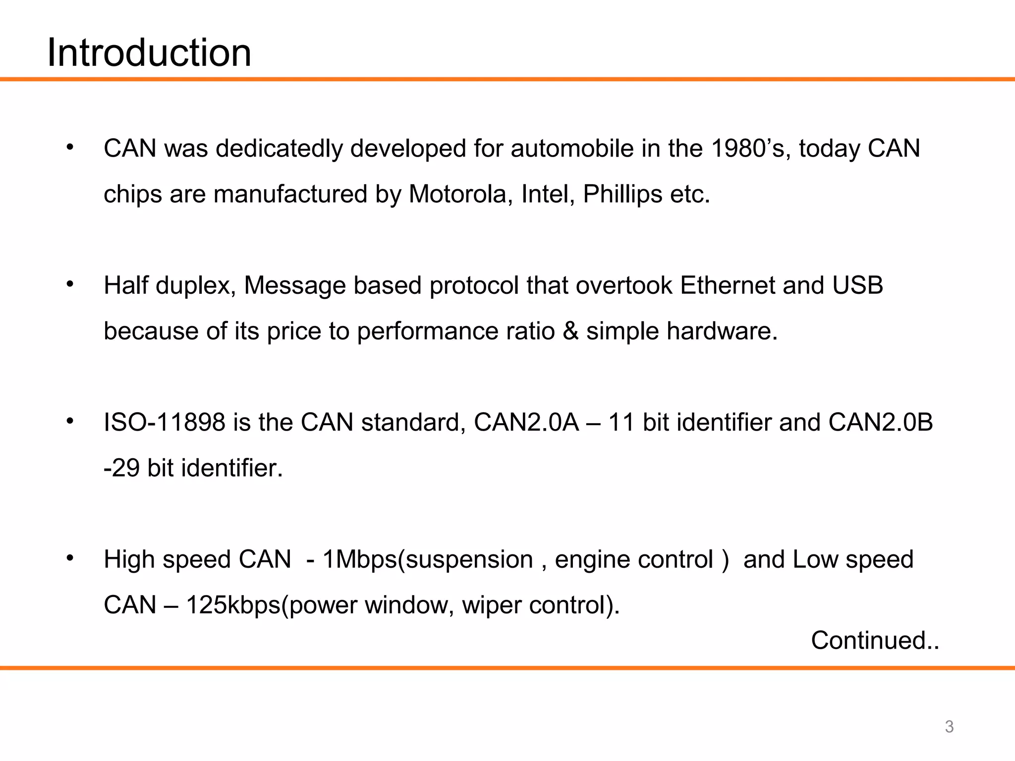
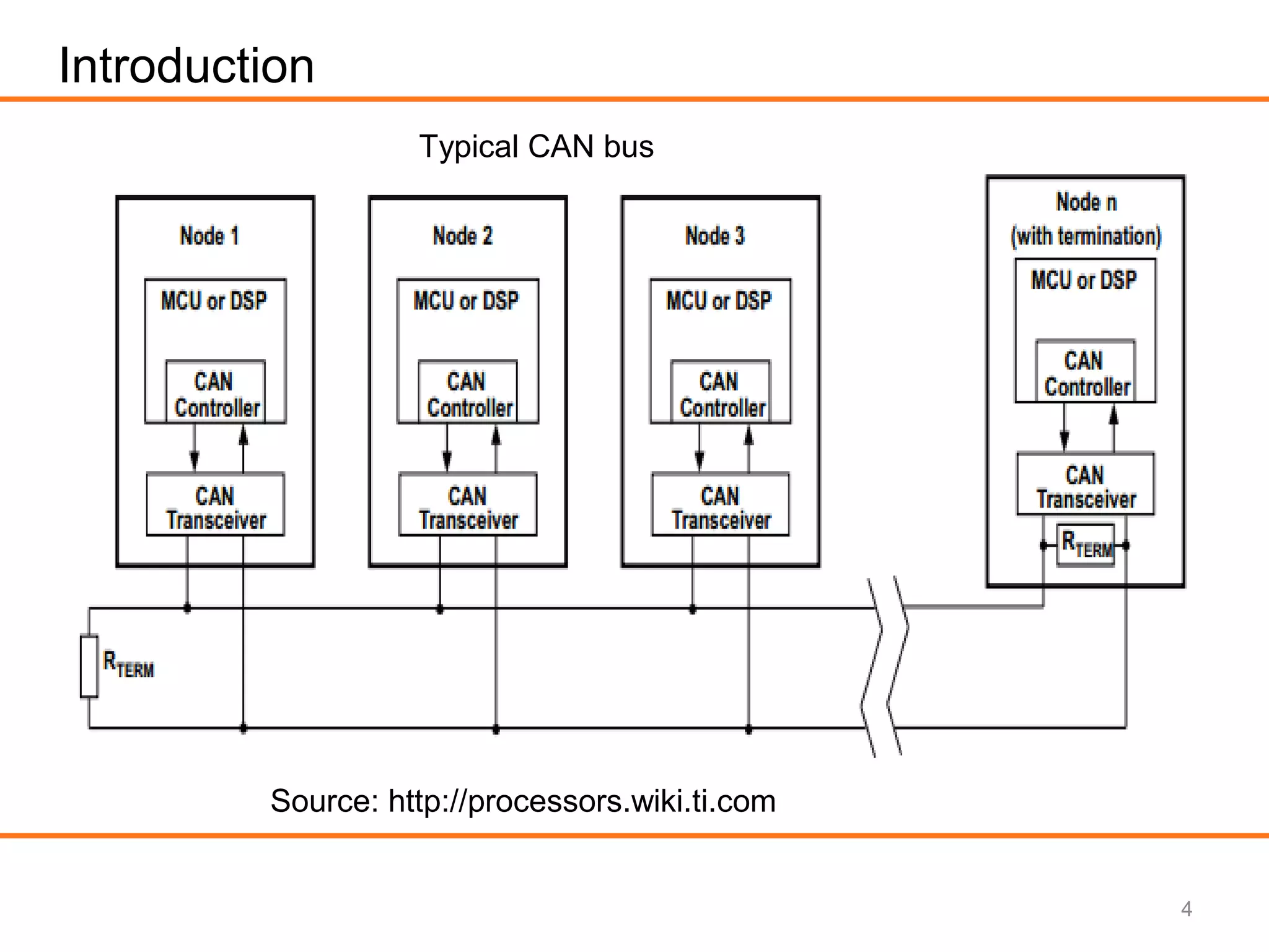
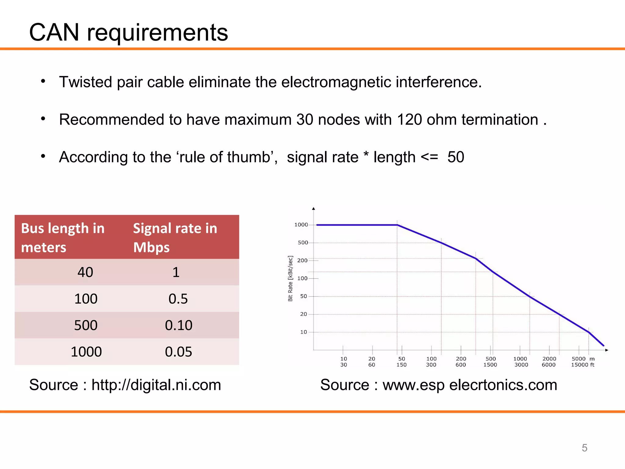
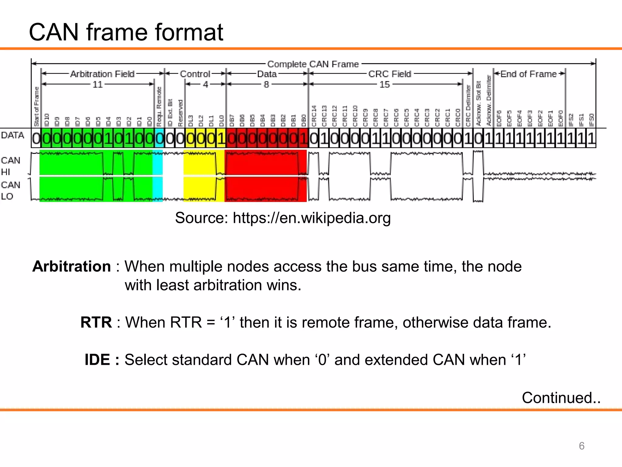
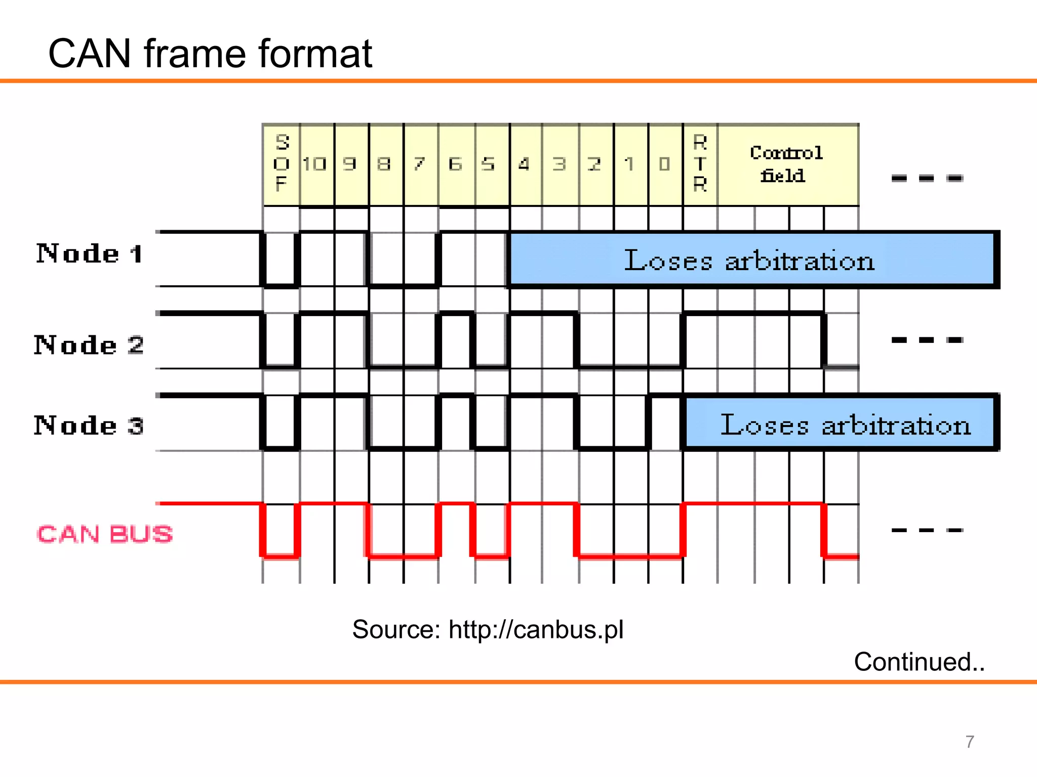
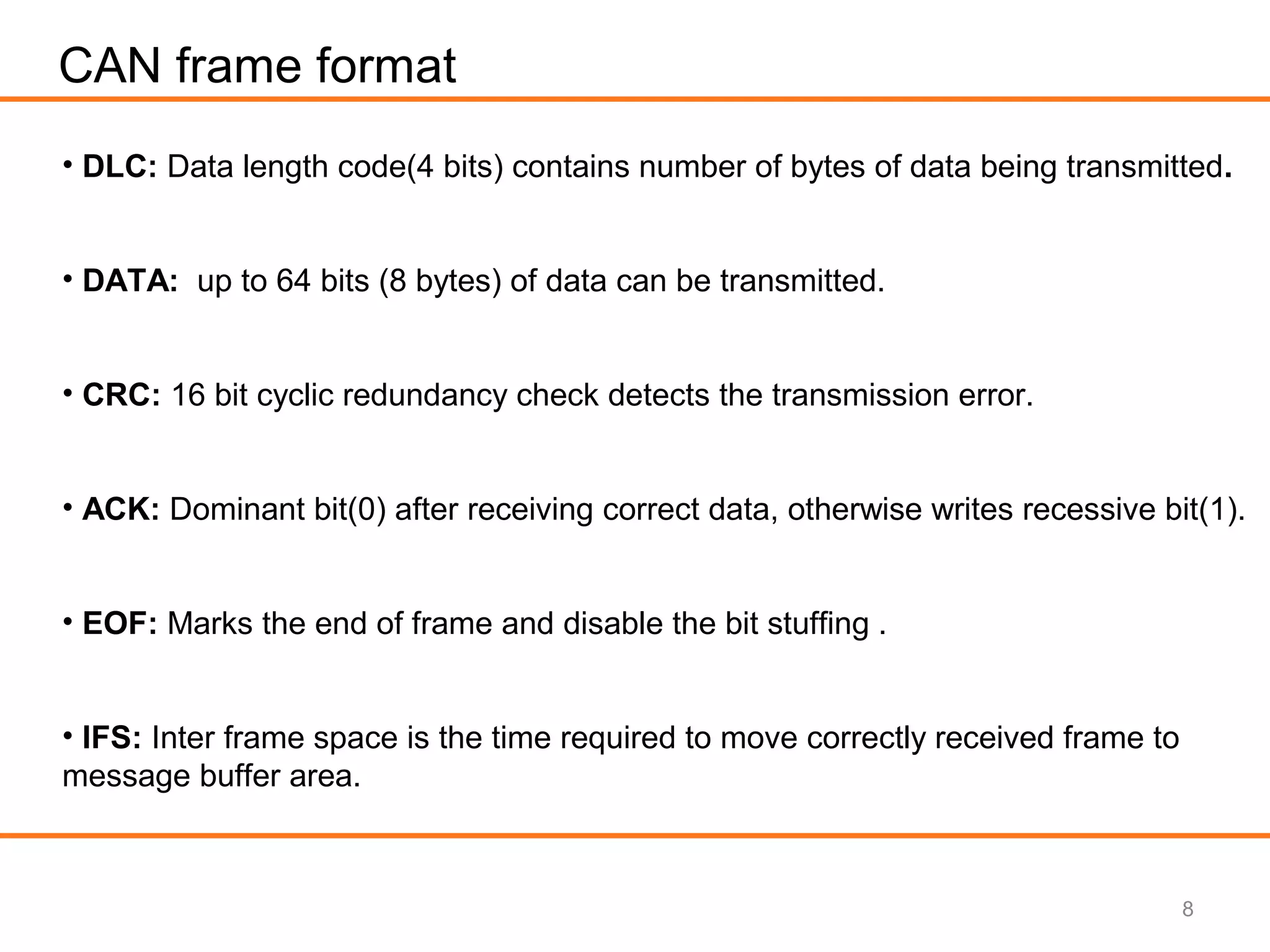
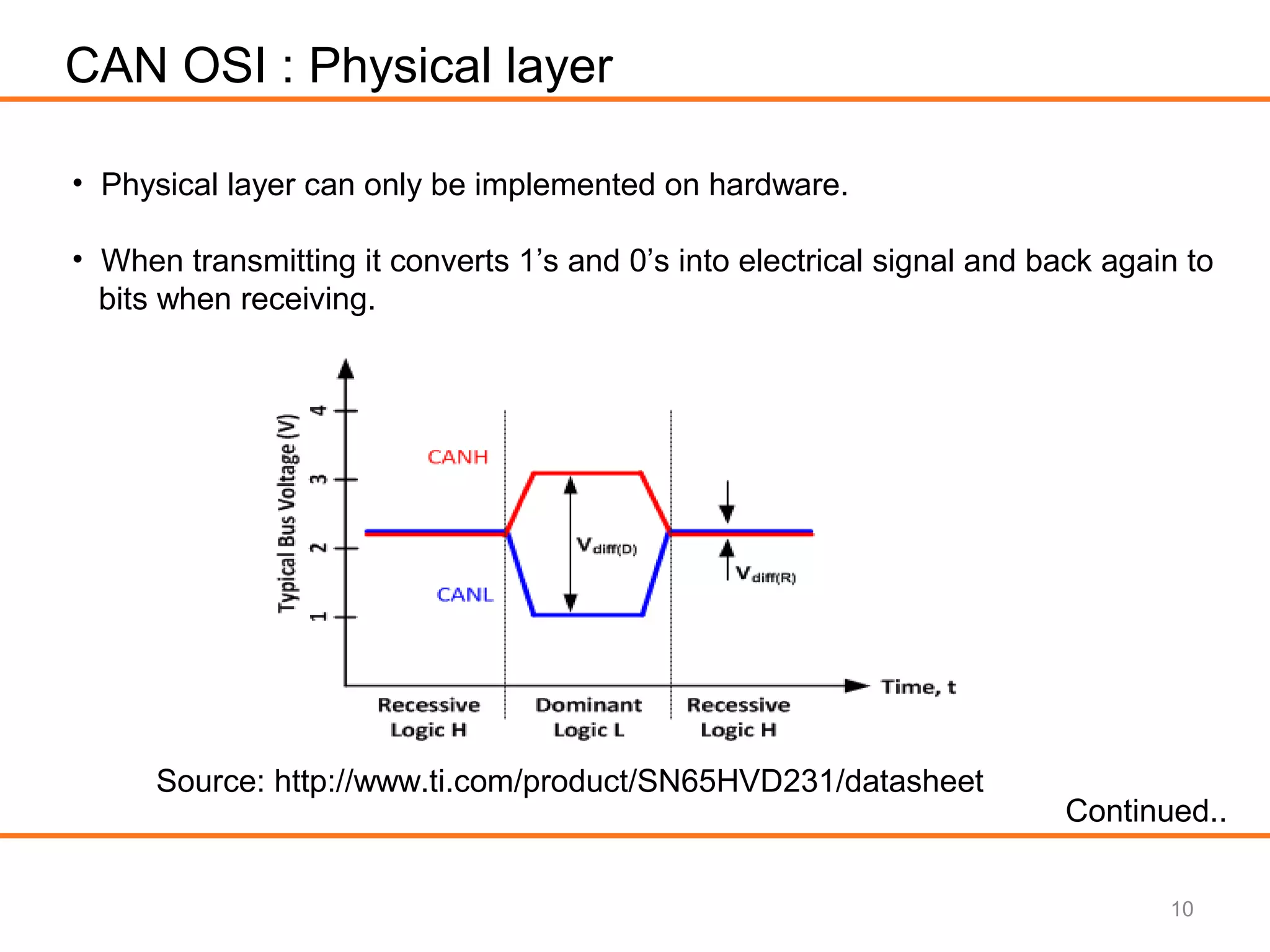
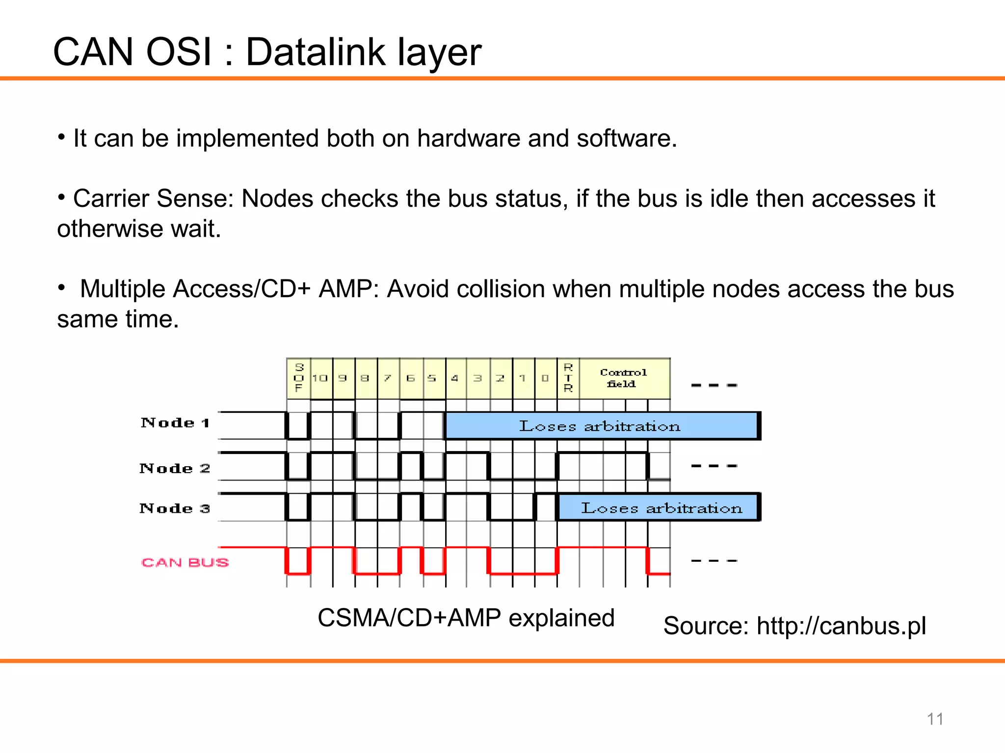
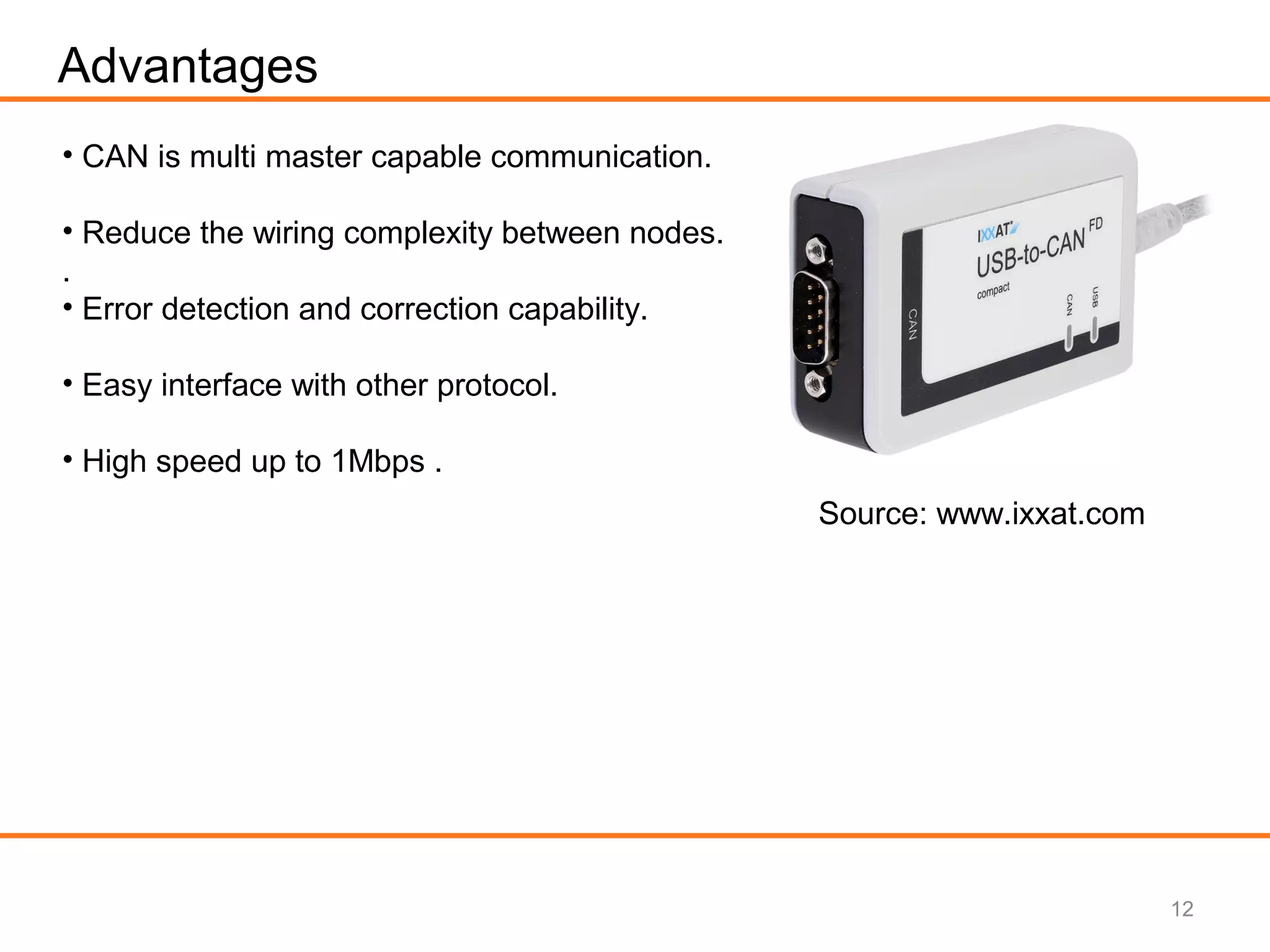
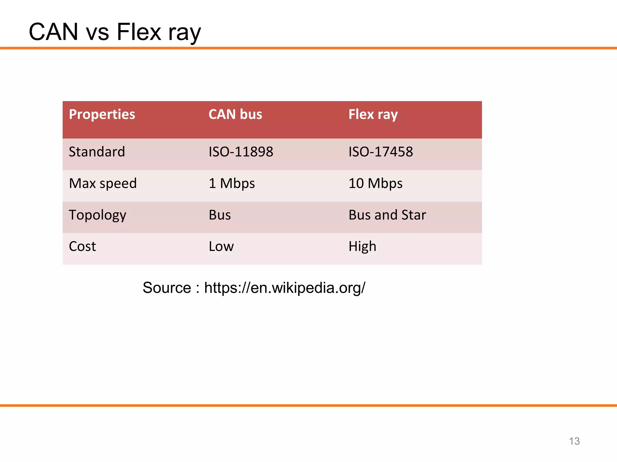
This document provides an overview of CAN BUS systems used in automotive applications. It discusses the requirements for CAN BUS, including the use of twisted pair cable and termination resistors. The document describes the CAN frame format, including the arbitration, control, data, and CRC fields. It explains the OSI layers for CAN, including the physical layer that transmits electrical signals and the data link layer that handles carrier sensing and collision avoidance. Advantages of CAN BUS are its support for multiple masters, reduced wiring complexity, error detection capabilities, and high speeds up to 1Mbps. CAN BUS is also compared to FlexRay, with CAN having lower cost but lower maximum speed.


![Seller Deck - Presentation [Concert L2].PPTX](https://cdn.slidesharecdn.com/ss_thumbnails/sellerdeck-presentationconcertl2-251219171156-24982daf-thumbnail.jpg?width=640&height=640&fit=bounds)


