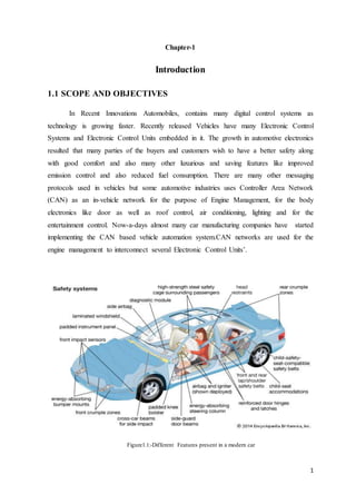
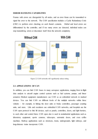
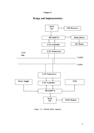
The document provides an overview of a proposed remote vehicle control and tracking system using Controller Area Network (CAN) protocol. The system would allow a vehicle owner to remotely lock or unlock their car and track its location using GPS and GSM technology. CAN is implemented to enable communication between electronic control units in the vehicle for functions like engine management and body controls. The working involves sending location updates via text message when the car starts and allowing the owner to reply to perform remote actions like locking the vehicle.
This report was submitted in partial fulfillment of requirement of Bachelor degree in Computer Science & Engineering in Veer Surendra Sai University of Technology, Burla, Odisha, India.
This pdf is about the CAN communication protocol, which is vital for automobiles.A Brief Overview. The CAN bus protocol is defined by the ISO 11898-1 standard and can be summarized like this: The physical layer uses differential transmission on a twisted pair wire. A non-destructive bit-wise arbitration is used to control access to the bus. This is made with the help of Engineersgarage.
which is used in automobiles which has speed up to 1mbs bits in a 40 meter length cable, it is implemented in where there is of multiple networks ,it has wide range of applications in automobile , in this ppt we show implimentation of can using xilinx
An overview of the communication stack within the classical AUTOSAR
- AUTOSAR Static architecture
- Communication stack
- CAN stack
- PDU-ROUTER
LINKS:
---------
https://www.autosar.org/
In recent years, rapid growth in the field of electronics and computer technology which makes the life simpler and faster. This development hits the automobile sector, which makes increases the systems in vehicle like infotainment system, safety system and security system. These systems are integrated to know the status of the vehicle for each and every second, this is done by means of different networking protocols. In this paper, the different network architecture and protocols are discussed and which is best suited for automobile in the current scenario.
All the images used in my presentation are belonging to their respective owners. I do not own any copyright.
-------------------------------------------------------------------------------------
>> One of the Best, Semester-3 M.Tech Academic Seminar Presentation on "Controller Area Network Bus" or CAN Protocol.
>> One of the Automotive based protocols from Robert Bosch
>> Comes under In-Vehicle Networking (IVN) Technology
>> Includes most of the theoretical concepts of CAN
This presentation is about AUTOSAR CAN stack. it provides an overview about:
- Included modules
- How modules communicate with each other
- Transmission and reception of frames
- changing network states
please let me know in the comments if you have any enhancements or feedback.
International Journal of Engineering Research and DevelopmentIJERD Editor
Electrical, Electronics and Computer Engineering,
Information Engineering and Technology,
Mechanical, Industrial and Manufacturing Engineering,
Automation and Mechatronics Engineering,
Material and Chemical Engineering,
Civil and Architecture Engineering,
Biotechnology and Bio Engineering,
Environmental Engineering,
Petroleum and Mining Engineering,
Marine and Agriculture engineering,
Aerospace Engineering.
Controller Area Network (CAN) Different TypesFebinShaji9
Controller Area Network (or CAN) is the latest communication system within the automotive world. At its simplest level, it can be thought of as a means of linking all the electronic systems within a vehicle together to allow them to communicate with each other
Controller Area Network (CAN Bus)I need to know why this network i.pdffashiionbeutycare
Controller Area Network (CAN Bus)
I need to know why this network is important in a car
How does CAN Network works in a Automobile. please give complete details about how the
communication works.
Solution
There are four main applications for serial communication in vehicles, each having different
requirements and objectives.
Using CAN, peer stations (controllers, sensors and actuators) are connected via a serial bus. The
bus itself is a symmetric or asymmetric two wire circuit, which can be either screened or
unscreened. The electrical parameters of the physical transmission are also specified in ISO
11898. Suitable bus driver chips are available from a number of manufacturers.
The CAN protocol, which corresponds to the data link layer in the ISO/OSI reference model,
meets the real-time requirements of automotive applications. Unlike cable trees, the network
protocol detects and corrects transmission errors caused by electromagnetic interference.
Additional advantages of such a network are the easy configurability of the overall system and
the possibility of central diagnosis.The purpose of using CAN in vehicles is to enable any station
to communicate with any other without putting too great a load on the controller computer.
Principles of data exchange.
When data are transmitted by CAN, no stations are addressed, but instead, the content of the
message (e.g. rpm or engine temperature) is designated by an identifier that is unique throughout
the network. The identifier defines not only the content but also the priority of the message. This
is important for bus allocation when several stations are competing for bus access.
If the CPU of a given station wishes to send a message to one or more stations, it passes the data
to be transmitted and their identifiers to the assigned CAN chip (”Make ready”). This is all the
CPU has to do to initiate data exchange. The message is constructed and transmitted by the CAN
chip. As soon as the CAN chip receives the bus allocation (”Send Message”) all other stations on
the CAN network become receivers of this message (”Receive Message”). Each station in the
CAN network, having received the message correctly, performs an acceptance test to determine
whether the data received are relevant for that station (”Select”). If the data are of significance
for the station concerned they are processed (”Accept”), otherwise they are ignored.
A high degree of system and configuration flexibility is achieved as a result of the content-
oriented addressing scheme. It is very easy to add stations to the existing CAN network without
making any hardware or software modifications to the existing stations, provided that the new
stations are purely receivers. Because the data transmission protocol does not require physical
destination addresses for the individual components, it supports the concept of modular
electronics and also permits multiple reception (broadcast, multicast) and the synchronization of
distributed processes: m.
The CAN Bus (Controller Area Network) is a serial two-wire full-duplex communication specification which conforms to the international standard ISO-11898 standard communication interface. The protocol of the CAN bus allows multiple nodes in a system to communicate efficiently with each other. It is already widely used in vehicle and vessel internal components; in recent years, it has seen adoption in data communications and control in industrial industry. The CAN Bus is used on the data transfer and control between controllers, a common setup in various industries. Examples include military use, electric power measurement, building automation, semiconductor equipment and elevator networks. This type of monitoring system is made up of many single-device combinations. To verify that things are working properly, one relies upon the integrity of software.
Response time analysis of mixed messages in CANIJERA Editor
Controller Area Network (CAN) is a network protocol that allows multiple processors in a system to
communicate efficiently with each other. Microprocessors became small enough and powerful enough to start
appearing everywhere, not just inside personal computers. A CAN system sends messages using a serial bus
network, with the individual nodes (processors) in the network linked together in a daisy chain. Every node in
the system is equal to every other node. Any processor can send a message to any other processor, and if any
processor fails, the other systems in the machine will continue to work properly and communicate with each
other.In modern vehicle technology CAN is used to reduce point to point wiring harness for vehicle automation
and for data communication. To overcome the drawbacks of analog vehicle driving interface, this paper presents
the development and implementation of a digital driving system for a semi-autonomous vehicle to improve the
driver-vehicle interface. This offers increased flexibility and expandability. This system uses sensors to
measure temperature, distance from the other car, presence of alcohol in car, position monitoring, theft
monitoring and etc., and sends a warning signal to the driver if any of the parameter goes out of range to avoid
accidents. In addition to this if accident occurs in any remote area then using vibration sensor, accident is
detected and SMS is send immediately using GSM and preventing him from potentially getting into a serious
problems.
In spinning industry, AC-drives are needed to rotate in synchronized speed to achieve quality
product. Because of the quick evolution of manufacturing processes, the demand for flexible automation
systems is on the rise. To meet these, distributed motion control architecture based on intelligent drives and
field bus communication tends more and more to replace the traditional solutions. Drive synchronization is
necessary in industries where minor difference in rotary movement make major difference in product quality.
Using CAN (Control Area Network) protocol we can drive multiple motor in synchronization with minimum
transmission gap. A control area network (CAN) based multi-motor synchronized motion control system with
an advanced synchronized control strategy is proposed. The strategy is to incorporate the adjacent crosscoupling
control strategy into the sliding mode control architecture. In this project we are going to
synchronize multiple AC motors using CAN protocol.
Wireless Controller Area Network (WCAN) PROTOCOL.
WCAN uses token frame method in
providing channel access to nodes in the system. This method
allow nodes to share a common broadcast channel by taking
turns in transmitting upon receiving the token frame that are
circulating around the network for a specified amount of time.
The token frame allows nodes to access the network one at a
time, giving ‘fair’ chance to all nodes to transmit, instead of
competing with one another. Message with highest priority has
the highest priority to transmit. The token frame method
provides high throughput in a bounded latency environment.
WCAN is tested in a simulation environment and is found
outperforms IEEE 802.11 in a ring network environment in
terms of network scalability and high data rate.
In this AUTOSAR layered architecture, Communication Stack or ComStack facilitates communication. Hence ComStack can be defined as a software stack that provides communication services to the Basic Software Modules and Application Layer or Application Software.
https://www.embitel.com/product-engineering-2/automotive/autosar/
IJERA (International journal of Engineering Research and Applications) is International online, ... peer reviewed journal. For more detail or submit your article, please visit www.ijera.com
Controller Area Network is an ideal serial bus design suitable for modern embedded system based networks. It finds its use in most of critical applications, where error detection and subsequent treatment on error is a critical issue. CRC (Cyclic Redundancy Check) block was developed on FPGA in order to meet the needs for simple, low power and low cost wireless communication. This paper gives a short overview of CRC block in the Digital transmitter based on the CAN 2.0 protocols. CRC is the most preferred method of encoding because it provides very efficient protection against commonly occurring burst errors, and is easily implemented. This technique is also sometimes applied to data storage devices, such as a disk drive. In this paper a technique to model the error detection circuitry of CAN 2.0 protocols on reconfigurable platform have been discussed? The software simulation results are presented in the form of timing diagram.FPGA implementation results shows that the circuitry requires very small amount of digital hardware. The Purpose of the research is to diversify the design methods by using VHDL code entry through Modelsim 5.5e simulator and Xilinx ISE8.3i.The VHDL code is used to characterize the CRC block behavior which is then simulated, synthesized and successfully implemented on Sparten3 FPGA .Here, Simulation and Synthesized results are also presented to verify the functionality of the CRC -16 Block. The data rate of CRC block is 250 kbps .Estimated power consumption and maximum operating frequency of the circuitry is also provided.
Various parameters in the industries can be monitored and controlled using CAN bus network integrated with Bluetooth Communication. Monitoring and controlling the industrial parameters involve a large amount of man power and time consumption. To overcome the need of huge man power and time consumption this technology was developed which makes use of single person for monitoring and controlling the entire network. This method has been implemented in order to reduce the usage of wires used for communication purpose and also to reduce the errors relating to the data transfer. In this project sensors are used to sense the variable industrial parameters and the CAN protocols are used for error free data transmission and data reception purpose along with Bluetooth, pic micro controllers are used for programming the CAN controller. The data transmission rate will be higher than other wireless systems. This application is user friendly and it can be achieved at a very low cost.
1. 1
Chapter-1
Introduction
1.1 SCOPE AND OBJECTIVES
In Recent Innovations Automobiles, contains many digital control systems as
technology is growing faster. Recently released Vehicles have many Electronic Control
Systems and Electronic Control Units embedded in it. The growth in automotive electronics
resulted that many parties of the buyers and customers wish to have a better safety along
with good comfort and also many other luxurious and saving features like improved
emission control and also reduced fuel consumption. There are many other messaging
protocols used in vehicles but some automotive industries uses Controller Area Network
(CAN) as an in-vehicle network for the purpose of Engine Management, for the body
electronics like door as well as roof control, air conditioning, lighting and for the
entertainment control. Now-a-days almost many car manufacturing companies have started
implementing the CAN based vehicle automation system.CAN networks are used for the
engine management to interconnect several Electronic Control Units’.
Figure1.1:-Different Features present in a modern car
2. 2
Existing System Proposed System
In existing system, there is no remote
car locking system implemented.
Only for the purpose avoiding the car
steeling this system used.
Also there is no possible ways for
finding the position of car after theft.
Drawbacks
There is no wireless system for data
transfer.
Finding location of car after theft is
not possible.
There is no remote controlling
process of car.
In this system, CAN protocol is
implemented for Communication.
GSM and GPS technology will help
for locating the car.
Remote controlling and locking is
possible here.
Advantages
Very effective method to avoid form
being theft.
Without car owner awareness no one
can start the engine.
Very fast response over control
remotely.
1.2 WORKING PRINCIPLE:
a. In proposed system whenever the vehicle is started by a person, a message with the GPS
coordinate along with the location of the vehicle will be sent as an SMS to the vehicle
owner’s number.
b. On receiving the message the vehicle owner will send a reply to lock or antilock that is
stop the vehicle or allow the vehicle to run.
c. The system at first checks and verifies the owner number and if exact it checks the SMS
sent and performs the corresponding action.
d. All this process is achieved through in vehicular network, CAN.
e. When the car engine is started it sends the information to the Master node in CAN which
in turn fetches the location coordinates attached with it and generates the SMS. On
receiving locking or anti-locking code it sends the respective command to the slave node
which takes the intended action.
4. 4
Chapter-2
Controller Area Network (CAN) Overview
2.1. CAN HISTORY
Bosch has developed the CAN in 1985 for in-vehicular communication. Before
days, automotive manufacturers have connected all electronic devices in vehicles using
point-to-point wiring systems respectively. Manufacturers have started using more
electronic units in vehicles, which have got resulted in bulk of wire connections that were
heavy and also very expensive. Then they have replaced wiring with in-vehicle networks,
which in turn reduced wiring cost, weight and complexity. CAN is a highly integrated serial
bus system for networking the intelligent devices, which has emerged as the standard in-
vehicle network. The automotive industry has quickly adopted CAN and in 1993 it became
the international standard known as ISO 11898.from 1994, many higher-level protocols
been standardized based on CAN. Many Other markets have been widely adopted these
additional protocols, which are now main standards for industrial communications.
2.2. CAN & ITS ADVANTAGES
LOW-COST AND LIGHTWEIGHT NETWORK
This decreases overall cost and weight in automobiles. An advantage to this is that
electronic control units (ECUs) can have a single CAN interface rather than Analog and
digital inputs to every device in the system. CAN provide inexpensive, durable network
which helps multiple CAN devices to communicate with one another.
BROADCAST MECHANISM FOR COMMUNICATION
All devices on the network see all transmitted messages. Each of the devices on the network
has a CAN controller chip and is therefore intelligent. This structure allows modifications to
CAN networks with minimal impact. Each device can decide if a message is relevant or if it
should be filtered. Additional non-transmitting nodes can be added without modification to
the network.
PRIORITYASSIGNMENT
This arbitration is non-destructive and results in non-interrupted transmission of the highest
priority message. Every message has a priority, so if two nodes try to send messages
simultaneously, the one with the higher priority gets transmitted and the one with the lower
priority gets postponed.
5. 5
ERROR HANDLING CAPABILITIES
Frames with errors are disregarded by all nodes, and an error frame can be transmitted to
signal the error to the network. The CAN specification includes a Cyclic Redundancy Code
(CRC) to perform error checking on each frame's contents. Global and local errors are
differentiated by the controller, and if too many errors are detected, individual nodes can
stop transmitting errors or disconnect itself from the network completely.
Figure 2.2 CAN networks will significantly reduce wiring
2.3. APPLICATIONS OF CAN
In addition, you can find CAN buses in many aerospace applications, ranging from in-flight
data analysis to aircraft engine control systems such as fuel systems, pumps, and linear
actuators. Medical equipment manufacturers use CAN as an embedded network in medical
devices. You can find CAN on different levels of the multiple networks within these
vehicles – for example, in linking the door units or brake controllers, passenger counting
units, and more. Lifts and escalators use embedded CAN networks, and hospitals use the
CAN open protocol to link lift devices, such as panels, controllers, doors, and light barriers,
to each other and control them. CAN open also is used in nonindustrial applications such as
laboratory equipment, sports cameras, telescopes, automatic doors, and even coffee
machines. Railway applications such as streetcars, trams, undergrounds, light railways, and
long-distance trains incorporate CAN.
6. 6
In fact, some hospitals use CAN to manage complete operating rooms. Hospitals control
operating room components such as lights, tables, cameras, X-ray machines, and patient
beds with CAN-based systems. CAN also have applications in aircraft with flight-state
sensors, navigation systems, and research PCs in the cockpit. CAN was first created for
automotive use, so its most common application is in-vehicle electronic networking.
However, as other industries have realized the dependability and advantages of CAN over
the past 20 years, they have adopted the bus for a wide variety of applications.
2.4 TERMINOLOGY OF CAN
All CAN devices will send data across CAN networks in the form of packets called frames.
And a CAN frame will have following sections.
Frame -- Frames also are referred to as messages. An entire CAN transmission has
arbitration ID, data bytes, acknowledge bit.
Figure 2.4.1:-Frame Format of CAN.
SOF (start-of-frame) bit –it always indicates the beginning of a message with a
dominant bit that is logic 0.
Arbitration Mechanism ID –. Frames will come in two formats -- standard, which
uses a 11-bit arbitration ID, and will be extended, which always uses a 29-bit arbitration
ID and also it identifies a message will indicate the message's priority
Identifier Extension bit – it allows to diffrentiate between standard and the extended
frames.
CAN Data Field – it will contain 0 to 8 bytes of data.
Data Length Code(DLC) –it indicates the no of bytes that the data field will contain.
Remote Transmission request bit – the recessive RTR bit that is (logic 1) will indicate
a remote frame. A dominant RTR bit that is (logic 0) will indicate a data frame. It also
serves to differentiate a remote frame from the data frame.
cyclic redundancy check(CRC) – it contains 15-bit cyclic redundancy check code and
a recessive delimiter bit and the CRC field is used for the error detection.
Acknowledgement slot(ACK)– any CAN controller which receives the message will
send ACK bit at the end of a message. Therefore the transmitting node will check the
7. 7
presence of the ACK bit on bus and will attempt transmission again if there is no
acknowledgement is detected.
In below figure six channels that contained in the data field of a single CAN frame. Here
each signal contains 8 bits of data.
Figure 2.4.2:- Defining Signals inside the CAN frame.
2.5 HOW THE COMMUNICATION IN CAN WORKS
There is no master control when individual nodes have access to read and write data on
CAN bus. CAN will be peer-to-peer network. When CAN node is ready to transmit data, it
checks to see whether bus is busy and then it simply writes a CAN frame onto network. The
CAN frames transmitted has no addresses of either the transmitting node or receiving
nodes. An arbitration ID that is unique throughout the network labels the frame.
All nodes on the CAN network will receive the CAN frame, depending on the arbitration ID
of that transmitted frame, each CAN node on the network decides whether to accept the
frame. If multiple nodes try to transmit a message on to the CAN bus at a time, the node
with the highest priority (lowest arbitration ID) will automatically get bus access.
Nodes with Lower-priority should wait until bus become available before trying to transmit
again.
8. 8
Figure 2.5:- CAN will contain inbuilt priority for the messages to avoid conflicts.
9. 9
Chapter-3
Design and Implementation
Figure 3.1:- Module Block diagram
CAN Controller
PIC16F877A
PIC16F877A
CAN Controller
Power Supply
CAN
Bus
CANH
CANL
PIC16F877A
CAN Transceiver
CAN Transceiver
LCD
Relay Driver
DC Motor
MAX
232 GSM Modem
MAX
232 GPS Receiver
11. 11
3.1 REQUIREMENTS
3.1.1 HARDWARE REQUIREMENTS
Power Supply
PIC16F877A Controller
SIMCOM GSM board
GPS Receiver board
Liquid Crystal Display module
CAN Controller and CAN Transceiver
Alarm
DC Motor
MAX232
3.1.2 SOFTWARE REQUIREMENTS
Embedded C.
KEIL compiler
3.2 APPLICATIONS
It’s Very efficient way to avoid vehicle theft.
It can be applied in all vehicles.
One of the Easy way to trace the location of car when theft.
Engine can be put to Off State through wireless.
12. 12
Chapter-4
Overview of Hardware and Software
4.1. PIC16F887MICROCONTROLLER – DEVICE OVERVIEW
4.1.1. PIC16F877A INTRODUCTION
PIC16F877A is very convenient to use where coding, programming is easier. Main
advantage is it can write-erase because it uses FLASH memory technology. It has a number
of 40 pins where 33 pins for input and output. It contains many applications in
digital electronics circuits.
Figure 4.1.1:-PIC16F877A Microcontroller
13. 13
4.1.2 FEATURES OF MICROCONTROLLER -PIC16F877A
PIC16F877A series has advanced features compared to its previous series where important
features of PIC16F877A series are stated below.
4.1.2.1 GENERAL FEATURES OF PIC
o types of addressing modes such as direct, Indirect, relative addressing modes.
o Power on Reset (POR).
o Power-Up Timer and the oscillator start-up timer.
o Low power and high speed CMOS flash EEPROM.
o Full static design.
o Wide range of operating voltages (2.0 – 5.56) volts.
o High sink and source current (25mA).
o Commercial, industrial and extended temperature ranges.
o power consumption is Low and has High performance RISC CPU.
o contains 35 simple word instructions.
o Interrupt capability is up to 14 sources.
o contains 368×8bit of RAM, 256×8 of EEPROM, 8k×14 of flash memory.
4.1.2.2. PERIPHERAL FEATURES OF PIC
o Timer 0: 8 bit timer/counter that is pre-scalar.
o Timer 1:16 bit timer/counter which is pre-scalar.
14. 14
o Timer 2: is 8 bit timer/counter contains 8 bit period registers which will be pre-scalar
and post-scalar.
o 10bit multichannel Analog to Digital converter
o Synchronous Serial Port along with SPI (master code) and with I2C (master/slave).
o USART with 9 bit address detection capability.
o Parallel Slave Port that is 8 bit wide with the external RD, WR and CS controls.
4.1.2.3. KEY FEATURES OF PIC
o Maximum operating frequency is up to 20MHz.
o Flash program memory is 8KB.
o Data memory is up to 368.
o EEPROM data memory is up to 256.
o 5 in/out ports.
o contains 3 timers.
o there are 2 CCP modules.
o contains 2 serial communication ports i.e (MSSP, USART).
o PSP is parallel communication port
o 10bit A/D module i.e with 8 channels
15. 15
4.1.2.4. ANALOG FEATURES OF PIC
o has 10bit, up to 8 channel A-D converter.
o contains Brown Out Reset function.
o Analog comparator module is present.
4.1.2.5 SPECIAL FEATURES OF PIC
o capable of 100000 times erase and write cycle enhanced memory.
o capable of 1000000 times erase/write cycle data EEPROM memory.
o Self programmable under the software control.
o In-circuit serial programming, in-circuit debugging capability.
o has Single 5V, DC supply for circuit serial programming
o Programmable code protection is present.
o Power saving sleep modes.
o Selectable oscillator options.
16. 16
4.1.3 PIN CONFIGURATION OF PIC16F877A
There are 40 pins in this microcontroller IC. It has two 8 bit and one 16 bit timer
respectively. Capture and compare modules, serial ports, parallel ports and 5 input/output
ports are also present in it.
Figure 4.1.3:- Pin diagram of PIC16F877A Microcontroller
17. 17
4.1.4 DESCRIPTION OF PORTS IN PIC16F877A
PIC16F877A has 5 input and output ports. They are usually denoted by PORT A, B, C, D
AND E i.e (R A (RB) (RC) (RD) and (RE). These ports are all used for input and output
interfacing. In the controller, “PORT A” is 6 bits wide (RA-0 to RA-7), ”PORT B” ,
“PORT C”,”PORT D” will be8 bits wide (RB-0 to RB-7,RC-0 to RC-7,RD-0 to RD-7),
”PORT E” is 3 bit wide (RE-0 to RE-7).All the ports are all bi-directional ports. The
direction of port will be controlled by using TRIS(X) registers (TRIS A to set the direction
of PORT-A, TRIS B will set the direction for PORT-B, etc.). Setting TRIS(X) bit ‘1’ will
set a corresponding PORT(X) bit as an input. Clearing TRIS(X) bit ‘0’ will set the
corresponding PORT(X) bit as the output .If we want PORT A as input, just set the
TRIS(A) bit to logical ‘1’ and if we want to set PORT B as an output, just set the PORT B
bits to the logical ‘0’.
o AN0 TO AN7 (Analog input port): these ports are used for interfacing analog inputs.
o TX, RX: These are the USART transmission and reception ports.
o SCK: these pins are used for giving a synchronous serial clock input.
o SCL: these pins act as an output for both modes SPI and I2C.
o DT: synchronous data terminals.
o CK: synchronous clk input.
o SD0: SPI data output.
o SD1: SPI Data input.
o SDA: data input and output in I2C Mode.
o CCP1 and CCP2: these are capture, compare, PWM modules.
o OSC1: oscillator input and external clock.
18. 18
o OSC2: oscillator output or clock out.
o MCLR: master clr pin (Active low reset).
o Vpp: is programming voltage input.
o THV: High voltage test mode controlling pin.
o Vref (+/-): is reference voltage.
o SS: Slave select used for the synchronous serial port.
o T0CK1: indicates clock input to TIMER 0.
o T1OSO: indicates Timer 1 oscillator output.
o T1OS1: indicates Timer 1 oscillator input.
o T1CK1: indicates clock input to Timer 1.
o PGD: is Serial programming data.
o PGC: will be serial programming clock.
o PGM: is Low Voltage Programming input.
o INT: is an external interrupt.
o RD: will be Read control for parallel slave port.
o CS: is the Select control for parallel slave.
o PSP0 to PSP7: are Parallel slave ports.
o VDD: is positive supply for logic and input pins.
19. 19
o VSS: is Ground reference for logic and input or output pins.
4.1.5 PROGRAMING THE PIC16F877A
we have 5 input and output ports such as PORTA, PORTB, PORTC, PORTD, PORT E
which can be digital and also analog configured based on our requirements. In the case of
analog mode, ports can only act as inputs. There is a built in A/D converter used in such
cases. Multiplexer circuits are used in digital mode. We can configure the ports as output or
as input through programming. There is a register named as ‘TRIS’ which controls the
direction of ports. For different ports there are different registers such as TRISA, TRISB
etc. If we set a bit of the TRIS register to 0, then corresponding port bit will act as the
digital output. If we set a bit of the TRIS register to 1, then corresponding port bit will act as
the digital input. We use MP LAB IDE for programming and Proteus for Designing.
4.2 GSM MODULE
we use GSM modem for sending the information to the monitoring section as a message if
the buses are arrived at the bus stop. In monitoring section we have another GSM modem to
receive the message and upload the message in internet via max232.SIM908 module is a
Quad Band GSM and GPRS module which combines the GPS technology for the satellite
navigation. The compact design which has integrated GPRS and GPS in the SMT package
will save time and cost .Featuring an industry standard interface and a GPS function; it
allows variable assets to be tracked seamlessly at any location and anytime with signal
coverage.
4.2.1. GENERAL FEATURES OF GSM MODULE
o Uses Quad Band
o Operating at 850/900/1800/1900 MHz
o Has GPRS multi slot
o Is class 10
o GPRS mobile station is class B
o Will be Compliant to GSM phase 2/2+
o Is Class 4 (2 W @850/900 MHz)
o Is Class 1 (1 W @ 1800/1900MHz)
20. 20
o Has Dimensions: 30 x 30 x 3.2 mm
o Has Weight: 5.2 g
o Will Control via AT commands (GSM 07.07 ,07.05 and SIMCOM enhanced AT
Commands)
o Contains SIM application toolkit
o Supply voltage range for GPRS: 3.2 ~ 4.8 V,GPS: 3.0 ~ 4.5V
o Has Low power consumption
o Its Operation temperature: 40°
o Has C to +85 °C
4.2.2 GSM SPECIFICATIONS FOR DATA TRANSFER
o Has GPRS class 10: max. 85.6 kbps (downlink)
o Is PBCCH support
o Uses Coding schemes CS 1, 2, 3, 4
o Has CSD up to 14.4 kbps
o Will be USSD
o Is Non transparent mode
o Has PPP stack
o Is Integrated TCP/IP stack
4.2.3 GSM SPECIFICATIONS FOR SMS VIA GSM/GPRS
o Will have Point to point MO and MT
o Uses SMS cell broadcast
o Contains Text and PDU mode
4.2.4 GSM SPECIFICATIONS FOR GPS
o Is Receiver type
o Has 42channel
o Will have GPS L1 C/A code,
o Gives High performance
o Has STE engine
o Has Sensitivity
o Obtains Tracking: 160
o Uses dBm
21. 21
o Will have Cold starts: 143
o Uses Time To First Fix
o Has Accuracy Horizontal position : <2.5m CEP
o Uses Power consumption (GSM engine in idle mode)
o Has Acquisition 77mA
o Tracking 76mA
4.2.5 GSM SPECIFICATIONS FOR VOICE
o Is Tri codec
o Has Half rate (HR)
o Has Full rate (FR)
o Is Enhanced Full rate (EFR)
o Has Echo cancellation
o Will be Hands free
o Uses operation (Echo suppression)
4.2.6 GSM INTERFACES
o Will have 80pad
o Will be with SMT type
o Is Interface to external SIM 3V/ 1.8V
o Has Dual analog audio interfaces
o Contains RTC backup
o uses SPI interface
o has Serial interface and debug interface for GSM/GPRS
o will have Debug interface for GPS NMEA information output
o has Two separate antenna connectors for GSM/GPRS&GPS
22. 22
4.3. MAX232 OVERVIEW
It is used to convert the voltage level during communicate the data with microcontroller and
Personal Computer. Here message will be transmitted to the monitoring section via GSM
modem. To give the information to the GSM modem we are going for the max232. In this
project the position of the robot, the detection of the cracks will be send as the message to
the monitoring section.Max232 is designed by the Maxim Integrated Products. This IC has
been widely used in RS232 Communication in which the voltage level conversion is
required to make the TTL devices compatible with PC serial port. This chip will contain
charge pumps that pump the voltage to Desired Level. It can also be powered by single +5
volt power supply and output can be reached to +_7.5 volts.MAX232 will come with 16 Pin
Dip and other packages contain Dual Drivers. It is used as a hardware layer convertor for
two systems to communicate simultaneously.Max232 is to be used in most of the problems
of signal voltage level conversion.
Figure 4.3:- Pin Diagram of MAX 232 IC
23. 23
4.3.1 CONSTRUCTION OF MAX232 IC
MAX232 will be used in 16-pin DIP package. It has three major blocks .It can be powered
by 5 volts to make compatible with most of the embedded systems. First block is voltage
doubler, In this IC, switched capacitor techniques is used to make the voltage double .Once
the voltage is doubled second block will convert that voltage to +10 and -10. The third
block consists of 2 transmitters and 2 receivers which actually convert the voltage levels.
Figure 4.3.1.1:-Internal Circuit of MAX232 IC
24. 24
4.3.2 APPLICATION AND USES OF MAX232 IC
MAX232 is used for Serial communication. Here Problem arises when we have to
communicate between TTL logic and CMOS logic based systems. In TTL logic 0 is defined
is by 0 volt and 1 is defined by 5 volt so in this scenario this is a very handy IC to be
incorporated. RS232 is internationally defined standard named as EIA/TIA-232-E and in
this standard logic 0 is the voltage between +3 to +15 and logic 1 is defined as the voltage
between -3 to -15.
4.4 GPS RECIEVER MODULE
The GPS a satellite navigation system that will location, time information in all weather,
anywhere on the Earth, where there is an unobstructed line of sight to 4 or more GPS
satellites. It has been maintained by United States government which will be freely
accessible to any individual with a GPS receiver.GPS receivers will receive almanac data
from the satellite and calculate the position by calculating its distance from the visible
satellites and by using method called triangulation it will calculate its position. The data is
configured according to the standards set up by National Marine Electronics Association
(NMEA) and is serially transmitted at the baud rate of 4800 bps. The NMEA has developed
the standards that will describe the interface between various marine electronic
equipments. The standards allow the marine electronics to send information to the
computers and to other marine equipments.
Figure 4.4:-GPS Receiver
25. 25
4.5 DC MOTOR OVERVIEW
A DC motor has been designed to run on DC electric power. Two examples of pure DC
designs will be Michael Faraday's homo polar motor, and a ball bearing motor. The
common DC motor types are brushed and brushless types, which will use internal and
external commutation to create an oscillating AC current from DC source so they will not
be purely DC machines.
Figure 4.5:- Construction of DC Motor
26. 26
4.6. LCD DISPLAY
LCD display is an electronic display module and is commonly used in various devices and
circuits. These are easily programmable and economical which has no limitation of
displaying special and also even custom characters animations. A 16x2 LCD will mean that
it will display 16 characters per line and has 2 such lines. In the LCD each character will be
displayed in 5x7 pixel matrix. This LCD has 2 registers, Command and Data. The command
register will store the command instructions where command is an instruction given to the
LCD to do a predefined task such as initializing, clearing, setting the position of cursor,
controlling display etc. The data register will store data that is to be displayed on the LCD
which will be an ASCII value.
Figure4.6:-16x2LCD interfacing with PIC16F877A
27. 27
Table 4.6:-LCD PIN DESCRIPTION
Pin No Pin Function Pin Name
1 (0V) Ground Ground pin
2 5V (4.7V – 5.3V) Supply voltage Vcc pin
3 Contrast adjustment through a variable resistor VEE pin
4
when low Selects command register; and when high data
register
Register Select
pin
5 Low is to write to the register; High is to read from the register Read/write pin
6 It Sends data to data pins when the high to low pulse is given Enable pin
7
These are 8-bit data pins
DB0
8 DB1
9 DB2
10 DB3
11 DB4
12 DB5
13 DB6
14 DB7
15 (5V)Backlight VCC LED+
16 (0V)Backlight Ground LED-
28. 28
4.7 SOFTWARE REQUIREMENTS
4.7.1 MPLAB IDE
It is called as Integrated Development Environment, because it provides a single integrated
"environment" to develop code for embedded microcontrollers. MPLAB X IDE is software
that runs on a PC to develop applications for Microchip microcontrollers and digital signal
controllers. Unlike previous versions of the MPLAB IDE which were developed completely
in-house, MPLAB X IDE is based on the open source Net Beans IDE from Oracle. MPLAB
X Integrated Development Environment has brought many changes to PIC microcontroller
development tool chain. This path allowed us to add frequently requested features quickly
and easily, also providing much more extensible architecture to bring even more new
features in the future.
4.7.2 PROTEUS
Proteus is software for simulation of microprocessor, schematic capture, and also for PCB
design which has developed by Lab Center Electronics. It combines the ISIS schematic
capture and the ARES PCB layout programs in order to provide powerful, integrated tools
for a professional PCB Design. Here more advanced routing modes are also included in
Proteus PCB Design Level 2 and higher whilst simulation capabilities can be enhanced by
purchasing the Advanced Simulation option and/or micro-controller simulation capabilities.
Using this Proteus software a simulated connection can be given between the components
and tested before fetching the code into the Controller.
35. 35
References
[1] A. Saad and U. Weinmann, “Automotive software engineering and concepts,” GI.
Jahrestagung., vol. 34, pp. 318–319, 2003.
[2] E. Nickel, “IBM automotive software foundry,” in Proc. Conf. Comput. Sci. Autom.
Ind., Frankfurt, Germany, 2003.
[3] M. Wolf, A. Weimerskirch, and T. Wollinger, “State of the art: Embedding security in
vehicles,” EURASIP J. Embedded Syst., vol. 2007, no. 5, p. 1,2007.
[4] R. Charette, This Car Runs on Code. [Online]. Available: http://www.
spectrum.ieee.org/feb09/7649
[5] T. Nolte, H. Hansson, and L. L. Bello, “Automotive communications-past, current and
future,” in Proc. IEEE Int. Conf. Emerging Technol. Factory Autom., 2005, vol. 1, pp. 992–
999.
[6] K. H. Johansson, M. Torngren, and L. Nielsen, “Vehicle applications of controller area
network,” in Handbook of Networked and Embedded Control Systems. New York, NY,
USA: Springer-Verlag, 2005, pp. 741–765.
[7] T. Hoppe and J. Dittman, “Sniffing/replay attacks on CAN buses: A simulated attack on
the electric window lift classified using an adapted CERT taxonomy,” in Proc. Conf.
Embedded Syst. Security, 2007, pp. 1–6.
[8] T. Hoppe, S. Kiltz, and J. Dittmann, “Security threats to automotive CAN networks—
Practical examples and selected short-term countermeasures,” Rel. Eng. Syst. Safety, vol.
96, no. 1, pp. 11–25, Jan. 2011.
[9] K. Koscher et al., “Experimental security analysis of a modern automobile,”
in Proc. IEEE Security Privacy. Symp., Oakland, CA, USA, 2010,pp. 447–462.
[10] The EVITA project, 2008, Webpage. [Online]. Available: http://evita-project.org
[11] H. Schweppe, Y. Roudier, B. Weyl, L. Apvrille, and D. Scheuermann, “Car2X
communication: Securing the last meter—A cost-effective approach for ensuring trust in
36. 36
Car2X applications using in-vehicle symmetric cryptography,” in Proc. Conf. Veh.
Technol., San Francisco, CA, USA, 2011, pp. 1–5.
[12] H. Schweppe et al., “Securing Car2X applications with effective hardware Software
co-design for vehicular on-board networks,” in Proc. Conf. Autom. Security, Berlin,
Germany, 2011.
[13] D. K. Nilsson, U. E. Larson, and E. Jonsson, “Efficient in-vehicle delayed
data authentication based on compound message authentication codes,” in Proc. Conf. IEEE
68th Int. Conf. Veh. Technol., Calgary, BC, Canada, 2008, pp. 1–5.
[14] B. Groza and S. Murvay, “Efficient protocols for secure broadcast in controller area
networks,” IEEE Trans. Ind. Informa., vol. 9, no. 4,pp. 2034–2042, Nov. 2013.