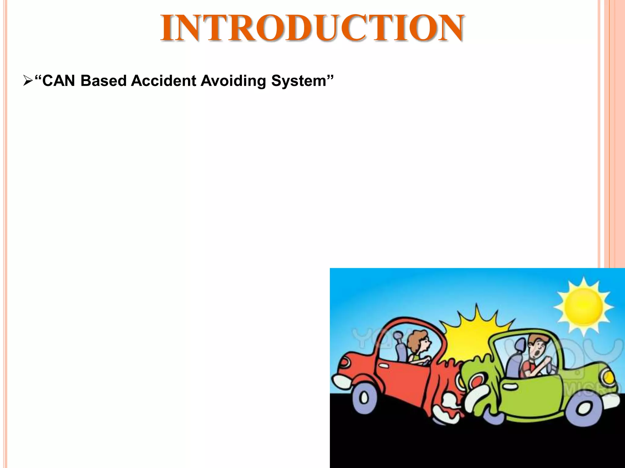
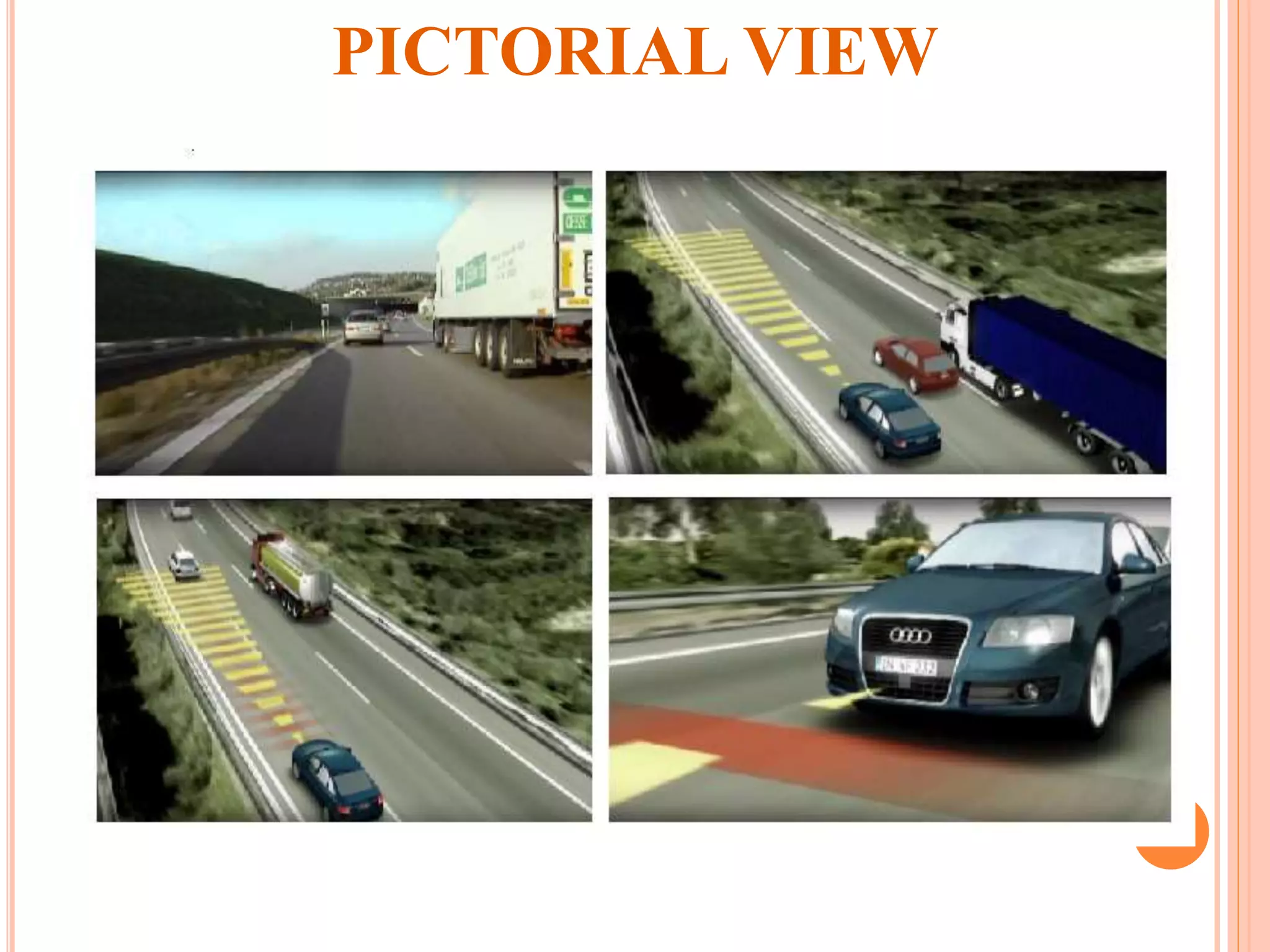
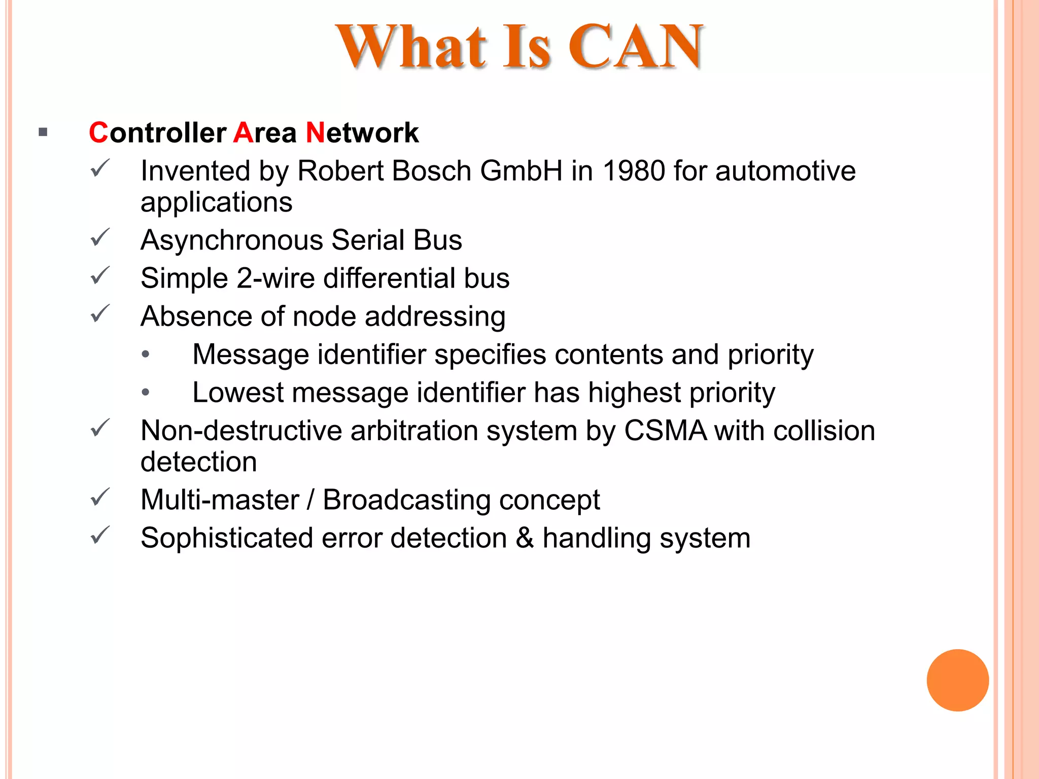
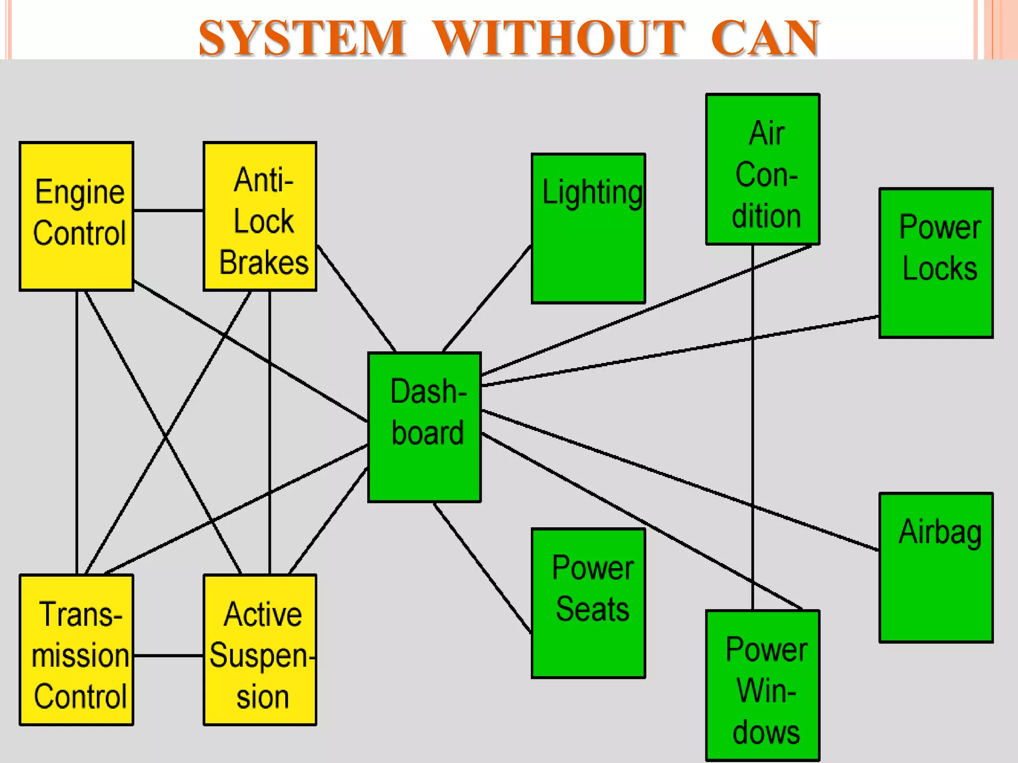
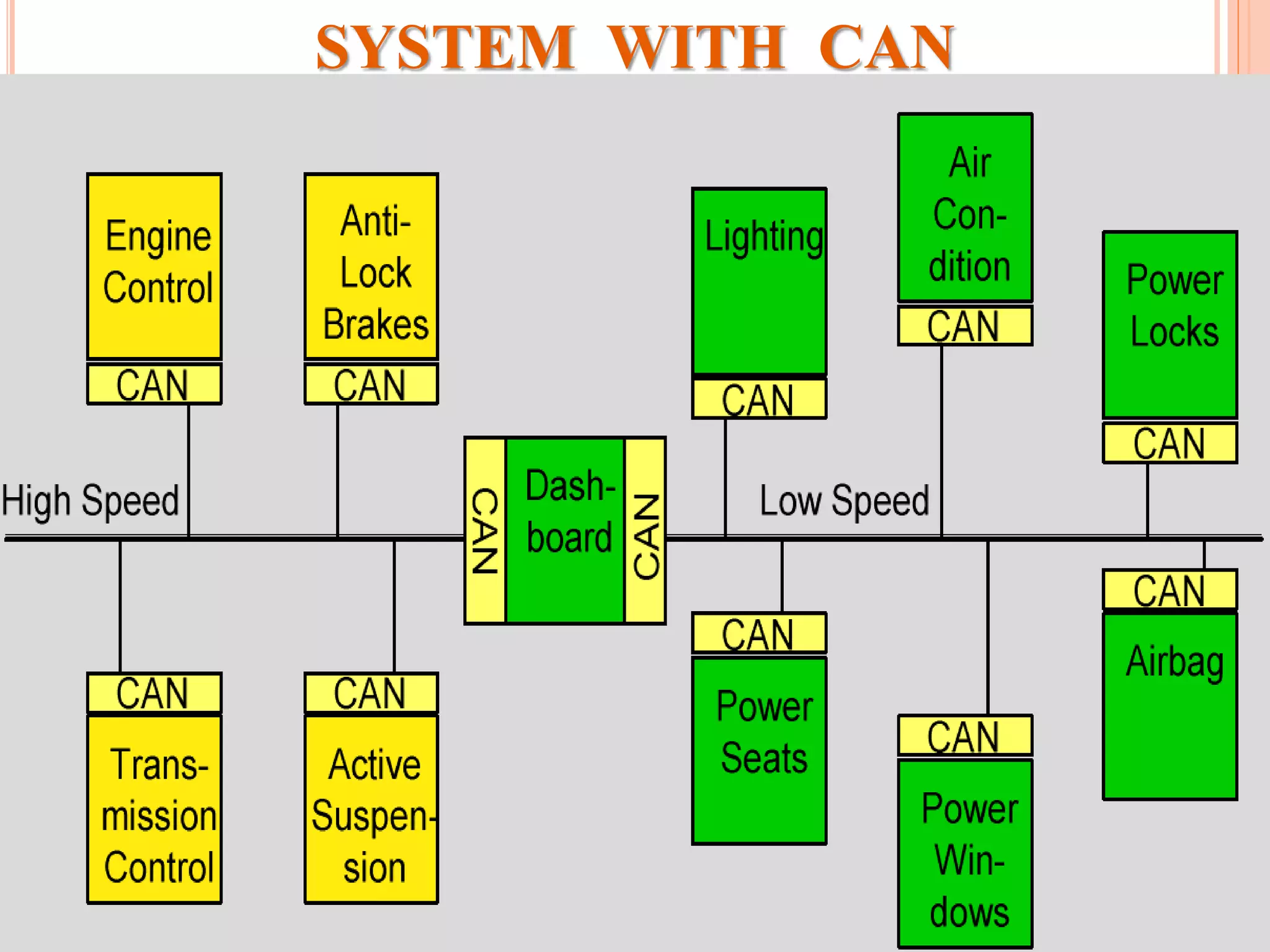
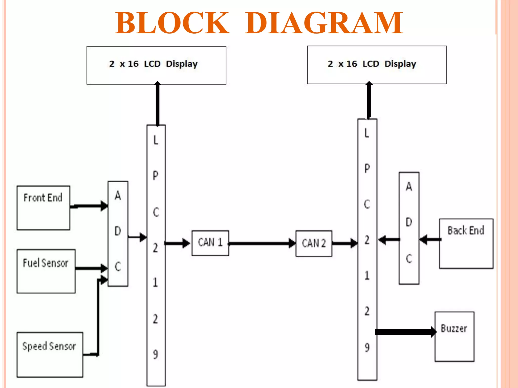
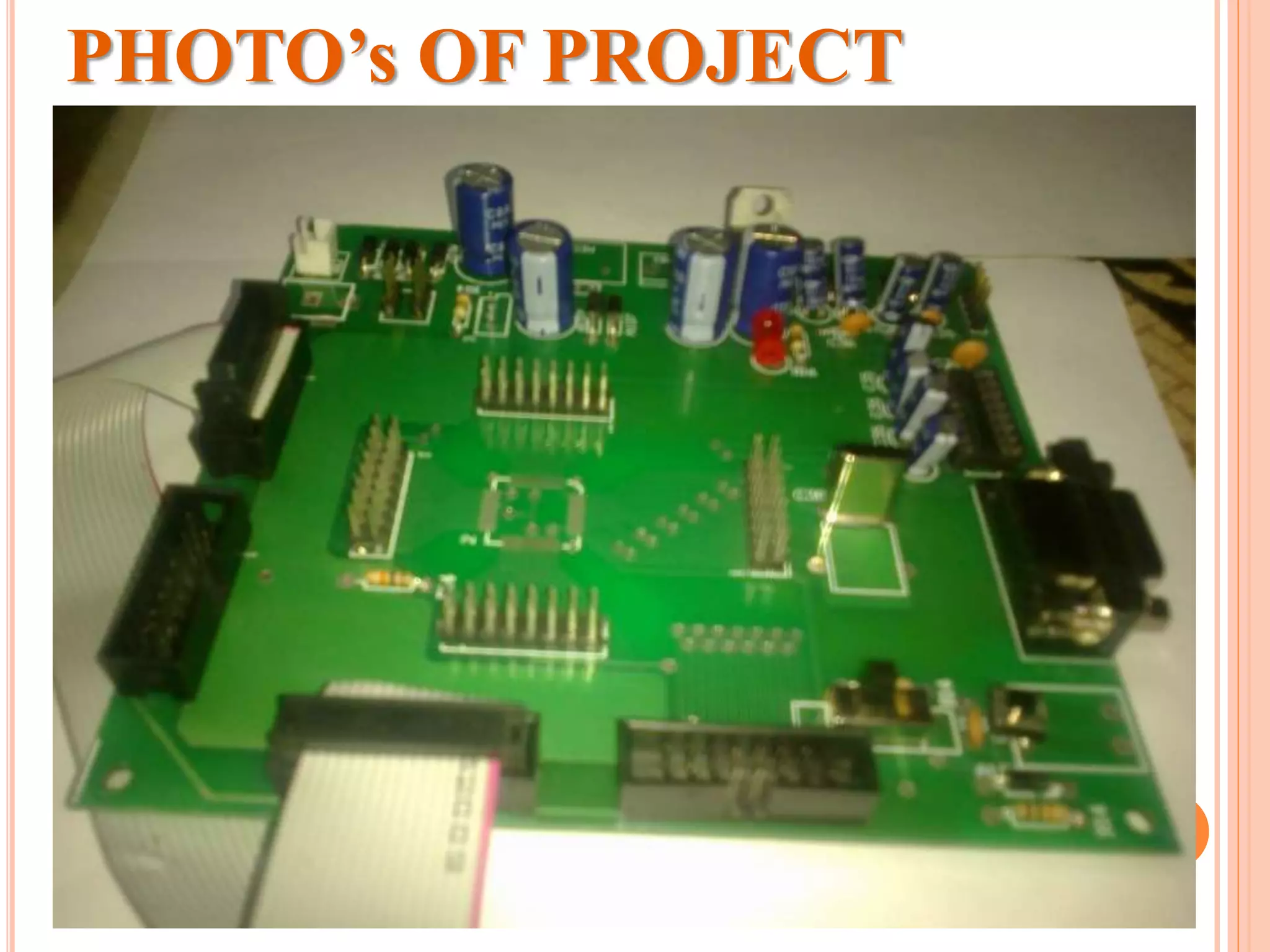
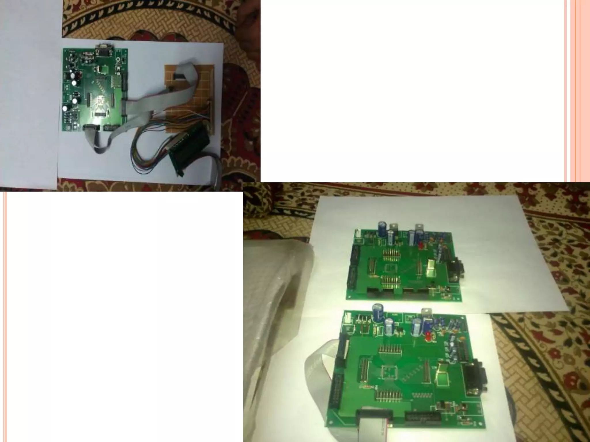
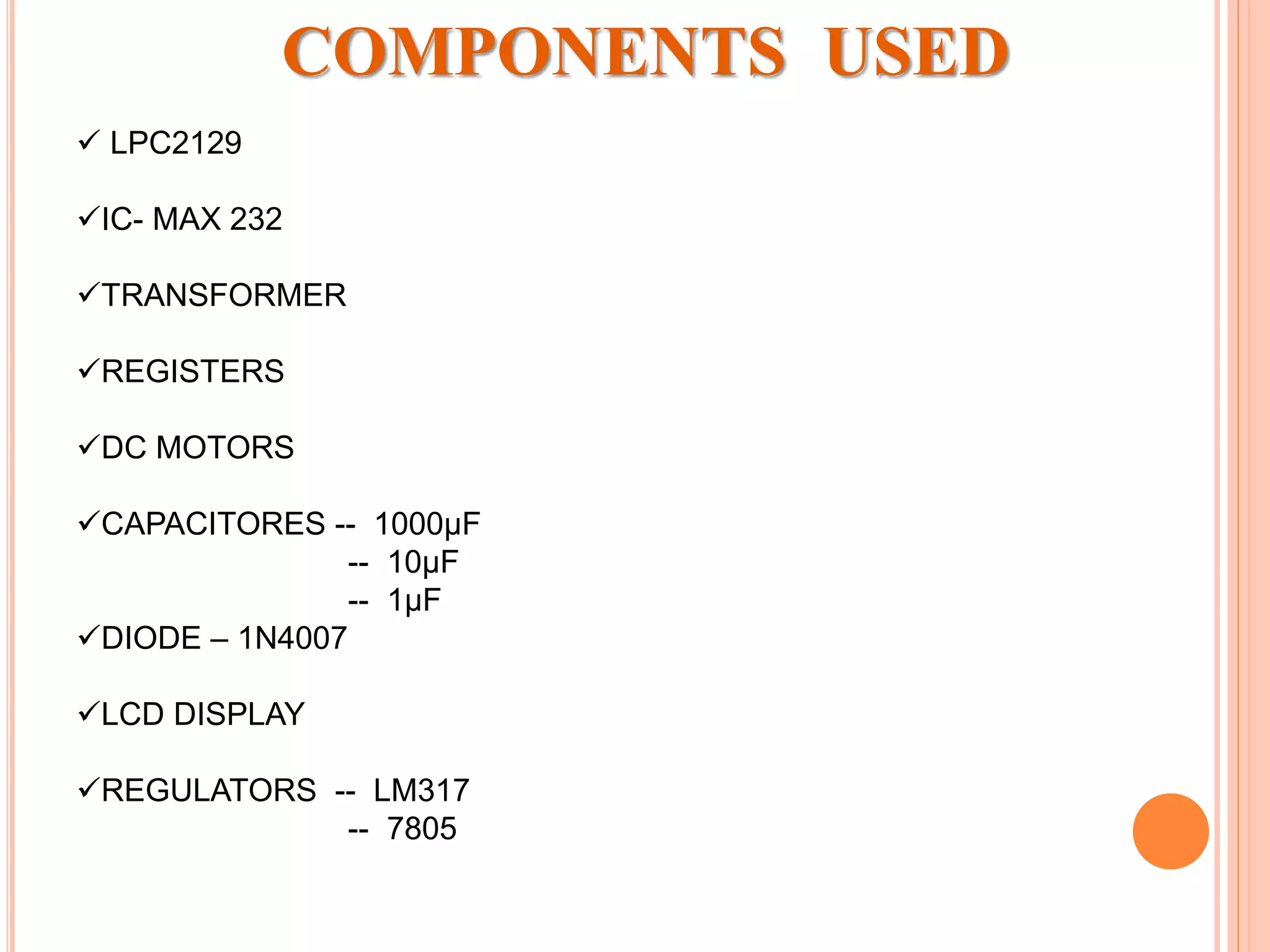
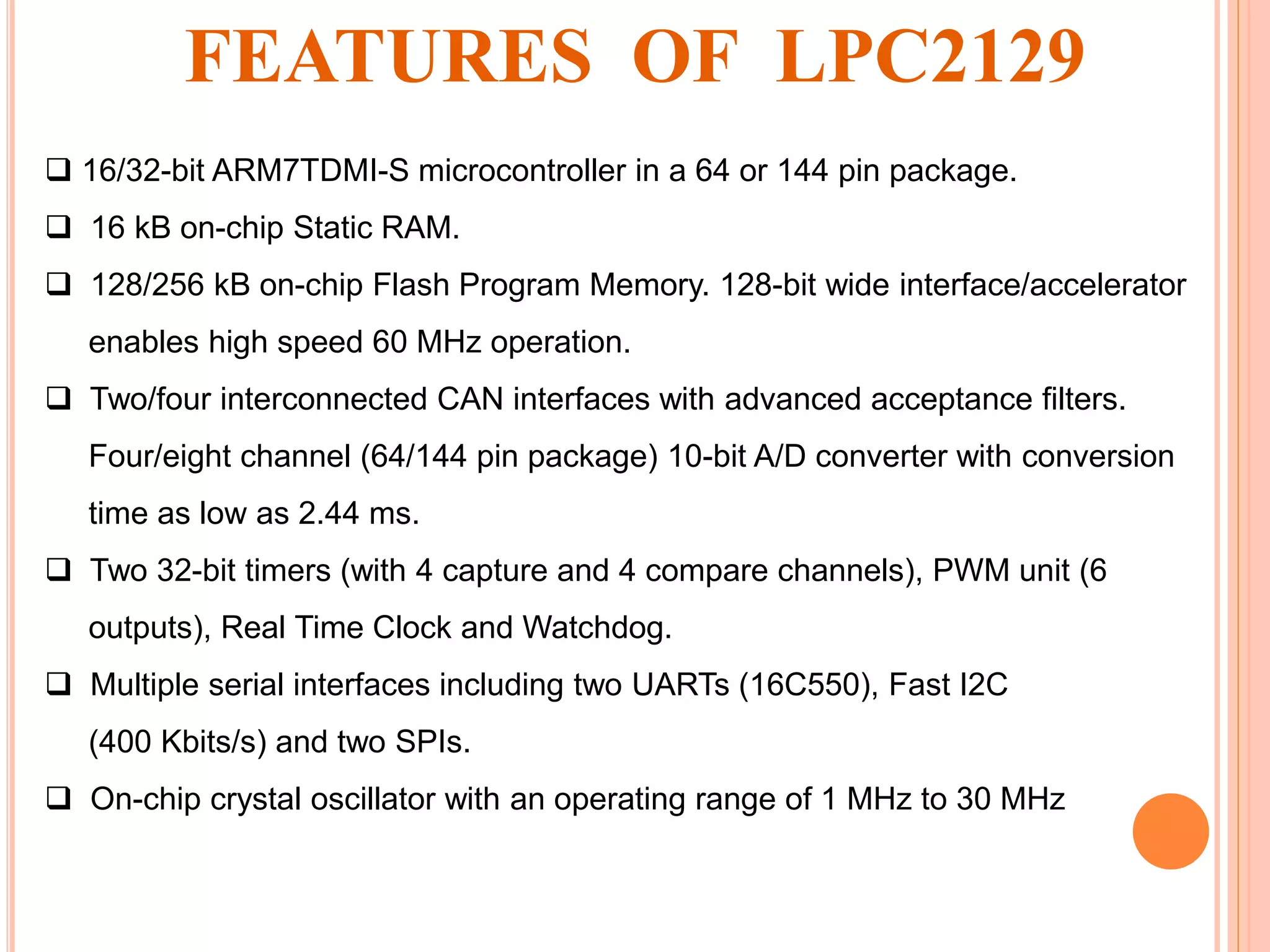
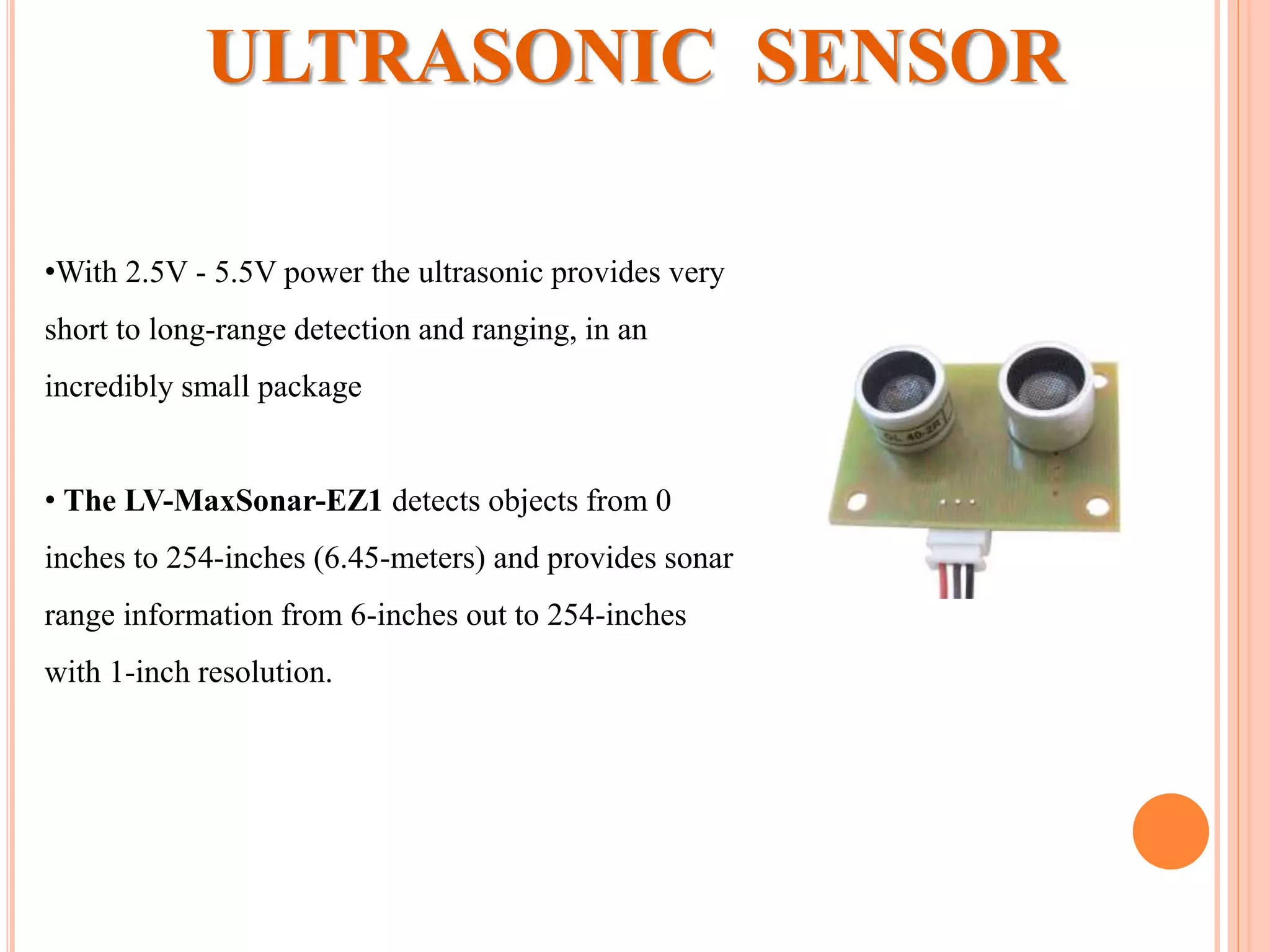
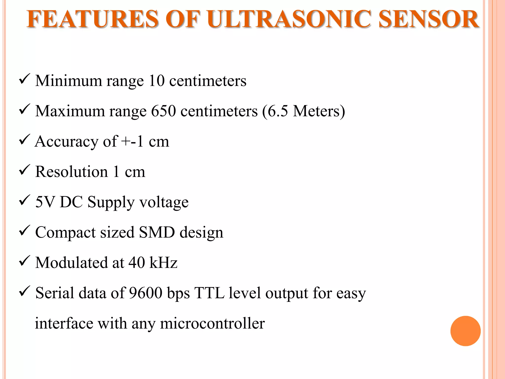
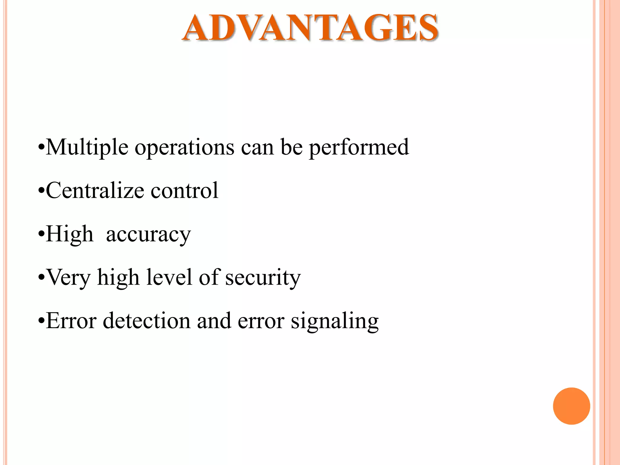
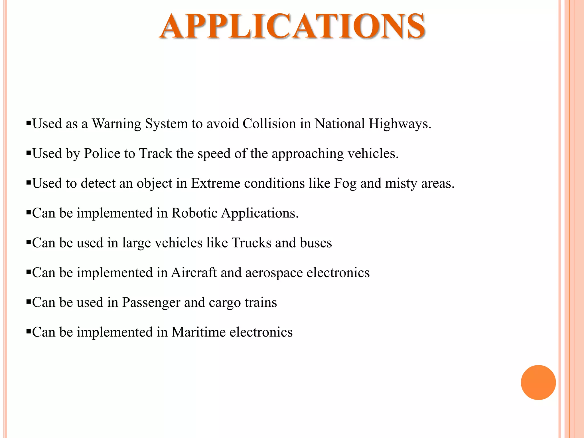
Dr. J J Magdum college of Engineering, Jaysingpur
Project on
“CAN based Accident Avoidance System”
 Presented by:
Nitin K Jagtap

21-Feb-2013 J.J.M.C.O.E(ENC)
ELECTRONICS AND COMMUNICATION DEPARTMENT
AGENDA
Introduction
Pictorial View
What is CAN?
Block Diagram
Components Used
Software's Used
Ultrasonic Sensor
Features of LPC2129
Applications
Advantages
INTRODUCTION
“CAN Based Accident Avoiding System”
PICTORIAL VIEW
What Is CAN
 Controller Area Network
 Invented by Robert Bosch GmbH in 1980 for automotive
applications
 Asynchronous Serial Bus
 Simple 2-wire differential bus
 Absence of node addressing
• Message identifier specifies contents and priority
• Lowest message identifier has highest priority
 Non-destructive arbitration system by CSMA with collision
detection
 Multi-master / Broadcasting concept
 Sophisticated error detection & handling system
SYSTEM WITHOUT CAN
SYSTEM WITH CAN
BLOCK DIAGRAM
SUB SYSTEMS
•FRONT END SUB SYSTEM
•RARE END SUB SYSTEM
PHOTO’s OF PROJECT
COMPONENTS USED
 LPC2129
IC- MAX 232
TRANSFORMER
REGISTERS
DC MOTORS
CAPACITORES -- 1000µF
-- 10µF
-- 1µF
DIODE – 1N4007
LCD DISPLAY
REGULATORS -- LM317
-- 7805
LED
SWITCHS
CONNECTORS & CABLES
BUZZER
ULTRA SONIC SENSOR
• KIEL Micro Vision4.
• LPC flash utility
SOFTWARE USED
 16/32-bit ARM7TDMI-S microcontroller in a 64 or 144 pin package.
 16 kB on-chip Static RAM.
 128/256 kB on-chip Flash Program Memory. 128-bit wide interface/accelerator
enables high speed 60 MHz operation.
 Two/four interconnected CAN interfaces with advanced acceptance filters.
Four/eight channel (64/144 pin package) 10-bit A/D converter with conversion
time as low as 2.44 ms.
 Two 32-bit timers (with 4 capture and 4 compare channels), PWM unit (6
outputs), Real Time Clock and Watchdog.
 Multiple serial interfaces including two UARTs (16C550), Fast I2C
(400 Kbits/s) and two SPIs.
 On-chip crystal oscillator with an operating range of 1 MHz to 30 MHz
FEATURES OF LPC2129
ULTRASONIC SENSOR
•With 2.5V - 5.5V power the ultrasonic provides very
short to long-range detection and ranging, in an
incredibly small package
• The LV-MaxSonar-EZ1 detects objects from 0
inches to 254-inches (6.45-meters) and provides sonar
range information from 6-inches out to 254-inches
with 1-inch resolution.
FEATURES OF ULTRASONIC SENSOR
 Minimum range 10 centimeters
 Maximum range 650 centimeters (6.5 Meters)
 Accuracy of +-1 cm
 Resolution 1 cm
 5V DC Supply voltage
 Compact sized SMD design
 Modulated at 40 kHz
 Serial data of 9600 bps TTL level output for easy
interface with any microcontroller
•Multiple operations can be performed
•Centralize control
•High accuracy
•Very high level of security
•Error detection and error signaling
ADVANTAGES
Used as a Warning System to avoid Collision in National Highways.
Used by Police to Track the speed of the approaching vehicles.
Used to detect an object in Extreme conditions like Fog and misty areas.
Can be implemented in Robotic Applications.
Can be used in large vehicles like Trucks and buses
Can be implemented in Aircraft and aerospace electronics
Can be used in Passenger and cargo trains
Can be implemented in Maritime electronics
APPLICATIONS
Any Quarries?
THANK YOU….

Control Area Network (CAN) based accident avoidance system

  • 1.
    Dr. J JMagdum college of Engineering, Jaysingpur Project on “CAN based Accident Avoidance System”  Presented by: Nitin K Jagtap  21-Feb-2013 J.J.M.C.O.E(ENC) ELECTRONICS AND COMMUNICATION DEPARTMENT
  • 2.
    AGENDA Introduction Pictorial View What isCAN? Block Diagram Components Used Software's Used Ultrasonic Sensor Features of LPC2129 Applications Advantages
  • 3.
  • 4.
  • 5.
    What Is CAN Controller Area Network  Invented by Robert Bosch GmbH in 1980 for automotive applications  Asynchronous Serial Bus  Simple 2-wire differential bus  Absence of node addressing • Message identifier specifies contents and priority • Lowest message identifier has highest priority  Non-destructive arbitration system by CSMA with collision detection  Multi-master / Broadcasting concept  Sophisticated error detection & handling system
  • 6.
  • 7.
  • 8.
  • 9.
    SUB SYSTEMS •FRONT ENDSUB SYSTEM •RARE END SUB SYSTEM
  • 10.
  • 12.
    COMPONENTS USED  LPC2129 IC-MAX 232 TRANSFORMER REGISTERS DC MOTORS CAPACITORES -- 1000µF -- 10µF -- 1µF DIODE – 1N4007 LCD DISPLAY REGULATORS -- LM317 -- 7805
  • 13.
  • 14.
    • KIEL MicroVision4. • LPC flash utility SOFTWARE USED
  • 15.
     16/32-bit ARM7TDMI-Smicrocontroller in a 64 or 144 pin package.  16 kB on-chip Static RAM.  128/256 kB on-chip Flash Program Memory. 128-bit wide interface/accelerator enables high speed 60 MHz operation.  Two/four interconnected CAN interfaces with advanced acceptance filters. Four/eight channel (64/144 pin package) 10-bit A/D converter with conversion time as low as 2.44 ms.  Two 32-bit timers (with 4 capture and 4 compare channels), PWM unit (6 outputs), Real Time Clock and Watchdog.  Multiple serial interfaces including two UARTs (16C550), Fast I2C (400 Kbits/s) and two SPIs.  On-chip crystal oscillator with an operating range of 1 MHz to 30 MHz FEATURES OF LPC2129
  • 16.
    ULTRASONIC SENSOR •With 2.5V- 5.5V power the ultrasonic provides very short to long-range detection and ranging, in an incredibly small package • The LV-MaxSonar-EZ1 detects objects from 0 inches to 254-inches (6.45-meters) and provides sonar range information from 6-inches out to 254-inches with 1-inch resolution.
  • 17.
    FEATURES OF ULTRASONICSENSOR  Minimum range 10 centimeters  Maximum range 650 centimeters (6.5 Meters)  Accuracy of +-1 cm  Resolution 1 cm  5V DC Supply voltage  Compact sized SMD design  Modulated at 40 kHz  Serial data of 9600 bps TTL level output for easy interface with any microcontroller
  • 18.
    •Multiple operations canbe performed •Centralize control •High accuracy •Very high level of security •Error detection and error signaling ADVANTAGES
  • 19.
    Used as aWarning System to avoid Collision in National Highways. Used by Police to Track the speed of the approaching vehicles. Used to detect an object in Extreme conditions like Fog and misty areas. Can be implemented in Robotic Applications. Can be used in large vehicles like Trucks and buses Can be implemented in Aircraft and aerospace electronics Can be used in Passenger and cargo trains Can be implemented in Maritime electronics APPLICATIONS
  • 20.
  • 21.