Downloaded 10 times

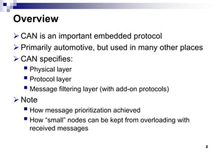
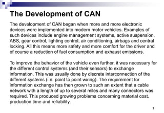
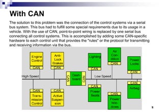


Control Area Network (CAN) Bus 1. CAN is a serial bus protocol used primarily in automotive applications to allow microcontrollers and devices to communicate with each other by transmitting short messages. 2. The development of CAN began as vehicles incorporated more electronic devices that needed to exchange information. This led to complex wiring that reduced reliability. 3. CAN specifies the physical layer, protocol layer, and message filtering to allow nodes to broadcast messages on the bus but only react to relevant messages through filtering.


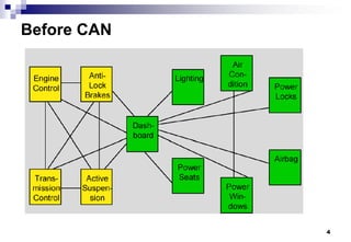
![Chapter2_fault tolerance [Compatibility Mode].pdf](https://cdn.slidesharecdn.com/ss_thumbnails/chapter2faulttolerancecompatibilitymode-241007004857-8eb7d95f-thumbnail.jpg?width=640&height=640&fit=bounds)