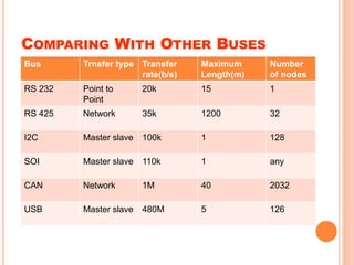
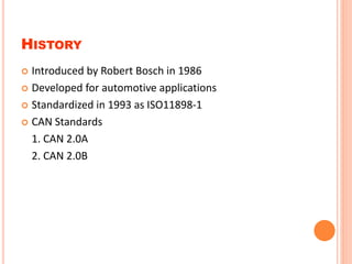
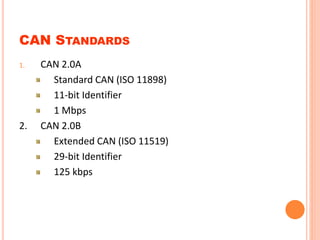
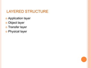
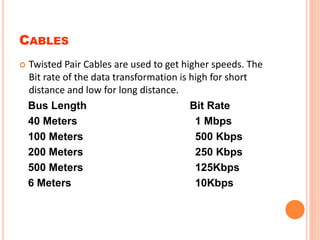
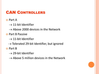
CAN
Controller Area Network
BY-Ashutosh Bhardwaj
Roll no. -1213231054
E.C-A
INTRODUCTION
 CAN bus is a vehicle bus standard designed to allow
microcontroller and devices to communicate with each
other in vehicle.
 It is a message based protocol.
 It is a multi-master serial bus
COMPARING WITH OTHER BUSES
Bus Trnsfer type Transfer
rate(b/s)
Maximum
Length(m)
Number
of nodes
RS 232 Point to
Point
20k 15 1
RS 425 Network 35k 1200 32
I2C Master slave 100k 1 128
SOI Master slave 110k 1 any
CAN Network 1M 40 2032
USB Master slave 480M 5 126
HISTORY
 Introduced by Robert Bosch in 1986
 Developed for automotive applications
 Standardized in 1993 as ISO11898-1
 CAN Standards
1. CAN 2.0A
2. CAN 2.0B
CAN STANDARDS
1. CAN 2.0A
Standard CAN (ISO 11898)
11-bit Identifier
1 Mbps
2. CAN 2.0B
Extended CAN (ISO 11519)
29-bit Identifier
125 kbps
APPLICATIONS
 Automobiles
 Aerospace
 Maritime
 Industrial automachine
 Medical equipments
LAYERED STRUCTURE
 Application layer
 Object layer
 Transfer layer
 Physical layer
NETWORK COMPONENTS
 Physical Layer
1. Cable.
2. Connector
3. Transreciever
 CAN Controller
1. Part A
2. Part B(Passive)
3. Part B
 Software
CABLES
 Twisted Pair Cables are used to get higher speeds. The
Bit rate of the data transformation is high for short
distance and low for long distance.
Bus Length Bit Rate
40 Meters 1 Mbps
100 Meters 500 Kbps
200 Meters 250 Kbps
500 Meters 125Kbps
6 Meters 10Kbps
CAN CONTROLLERS
 Part A
 11-bit Identifier
 Above 2000 devices in the Network
 Part B Passive
 11-bit Identifier
 Tolerated 29-bit Identifier, but ignored
 Part B
 29-bit Identifier
 Above 5 million devices in the Network
WORKING PRINCIPLE
 Uses CSMA/CD+AMP (Arbitration on Message Priority).
 Data messages transmitted from any node
 Using identifier all nodes will check whether the
message is intended for it or not
 The identifier determines the priority of the message
 Low bits are always dominant
FRAME TYPES
 Data Frame
 Remote Frame
 Error Frame
 Overload Frame
MESSAGE (DATA) FRAME
Standard Data Frame
Extended Data Frame
 Start Of Frame:
Logic 0 indicates the beginning of a message frame.
 Arbitration Field:
11-bit identifier. Determines the priority of the message.
 Control Field:
6-bits. 2-bits are reserved for future use. 4-bit Data
Length Code (DLC) indicates the number of bytes in the
data field.
 Data Field:
0 to 8 Bytes of data
 CRC Field:
15-bits Cyclic Redundancy Check Code and 1-bit delimiter
 Acknowledgement Field:
2-bits. Slot bit (1) overwritten by dominant bit from other
nodes and delimiter bit (1).
 End Of Frame Field:
7-bits (1111111). Indicates the End of the data frame.
Following the End Of Field is the Intermission field consisting
of 3-bits (111) denotes the bus is recognized to be free.
REMOTE FRAME
The intended purpose of this frame is to ask for the transmission of the
corresponding data frame. It is also used implement a type of request-
response type of bus traffic management.
ERROR FRAME
 Consists of error flag (6-bits) and error delimiter (8-bits).
 Transmitted when a node detects a fault and will cause
all other nodes to detect a fault
OVERLOAD FRAME
 This frame is mentioned just for completeness of the
transaction.
ADVANTAGES
 High throughput under light loads
 Local and global prioritization possible
LIMITATION
 Unfair access - node with a high priority can "hog" the
network.
 Poor latency for low priority nodes.
CONCLUSION
 CAN is ideally suited in applications requiring a large
number of short messages with high reliability in rugged
operating environments. Because CAN is message based
and not address based, it is especially well suited when
data is needed by more than one location and system-
wide data consistency is mandatory.

Controller Area Network(CAN)

  • 1.
    CAN Controller Area Network BY-AshutoshBhardwaj Roll no. -1213231054 E.C-A
  • 2.
    INTRODUCTION  CAN busis a vehicle bus standard designed to allow microcontroller and devices to communicate with each other in vehicle.  It is a message based protocol.  It is a multi-master serial bus
  • 3.
    COMPARING WITH OTHERBUSES Bus Trnsfer type Transfer rate(b/s) Maximum Length(m) Number of nodes RS 232 Point to Point 20k 15 1 RS 425 Network 35k 1200 32 I2C Master slave 100k 1 128 SOI Master slave 110k 1 any CAN Network 1M 40 2032 USB Master slave 480M 5 126
  • 4.
    HISTORY  Introduced byRobert Bosch in 1986  Developed for automotive applications  Standardized in 1993 as ISO11898-1  CAN Standards 1. CAN 2.0A 2. CAN 2.0B
  • 5.
    CAN STANDARDS 1. CAN2.0A Standard CAN (ISO 11898) 11-bit Identifier 1 Mbps 2. CAN 2.0B Extended CAN (ISO 11519) 29-bit Identifier 125 kbps
  • 6.
    APPLICATIONS  Automobiles  Aerospace Maritime  Industrial automachine  Medical equipments
  • 7.
    LAYERED STRUCTURE  Applicationlayer  Object layer  Transfer layer  Physical layer
  • 8.
    NETWORK COMPONENTS  PhysicalLayer 1. Cable. 2. Connector 3. Transreciever  CAN Controller 1. Part A 2. Part B(Passive) 3. Part B  Software
  • 9.
    CABLES  Twisted PairCables are used to get higher speeds. The Bit rate of the data transformation is high for short distance and low for long distance. Bus Length Bit Rate 40 Meters 1 Mbps 100 Meters 500 Kbps 200 Meters 250 Kbps 500 Meters 125Kbps 6 Meters 10Kbps
  • 10.
    CAN CONTROLLERS  PartA  11-bit Identifier  Above 2000 devices in the Network  Part B Passive  11-bit Identifier  Tolerated 29-bit Identifier, but ignored  Part B  29-bit Identifier  Above 5 million devices in the Network
  • 11.
    WORKING PRINCIPLE  UsesCSMA/CD+AMP (Arbitration on Message Priority).  Data messages transmitted from any node  Using identifier all nodes will check whether the message is intended for it or not  The identifier determines the priority of the message  Low bits are always dominant
  • 12.
    FRAME TYPES  DataFrame  Remote Frame  Error Frame  Overload Frame
  • 13.
    MESSAGE (DATA) FRAME StandardData Frame Extended Data Frame
  • 14.
     Start OfFrame: Logic 0 indicates the beginning of a message frame.  Arbitration Field: 11-bit identifier. Determines the priority of the message.  Control Field: 6-bits. 2-bits are reserved for future use. 4-bit Data Length Code (DLC) indicates the number of bytes in the data field.
  • 15.
     Data Field: 0to 8 Bytes of data  CRC Field: 15-bits Cyclic Redundancy Check Code and 1-bit delimiter  Acknowledgement Field: 2-bits. Slot bit (1) overwritten by dominant bit from other nodes and delimiter bit (1).  End Of Frame Field: 7-bits (1111111). Indicates the End of the data frame. Following the End Of Field is the Intermission field consisting of 3-bits (111) denotes the bus is recognized to be free.
  • 16.
    REMOTE FRAME The intendedpurpose of this frame is to ask for the transmission of the corresponding data frame. It is also used implement a type of request- response type of bus traffic management.
  • 17.
    ERROR FRAME  Consistsof error flag (6-bits) and error delimiter (8-bits).  Transmitted when a node detects a fault and will cause all other nodes to detect a fault
  • 18.
    OVERLOAD FRAME  Thisframe is mentioned just for completeness of the transaction.
  • 19.
    ADVANTAGES  High throughputunder light loads  Local and global prioritization possible
  • 20.
    LIMITATION  Unfair access- node with a high priority can "hog" the network.  Poor latency for low priority nodes.
  • 21.
    CONCLUSION  CAN isideally suited in applications requiring a large number of short messages with high reliability in rugged operating environments. Because CAN is message based and not address based, it is especially well suited when data is needed by more than one location and system- wide data consistency is mandatory.