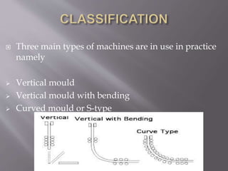
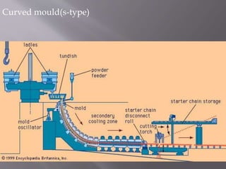
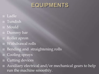
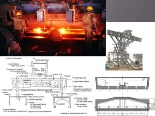
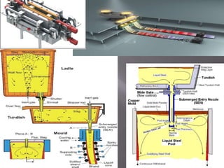
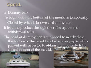
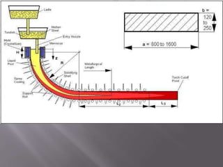
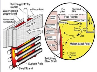
Department of Metallurgical Engineering
Gandhi Institute of Engineering and Technology, Gunupur
BIKASH RANJAN PRADHAN
11MET018
By
 Introduction
 Classification
 Equipments
 Materials required
 Process
 Defects
 Modern developments
 Advantages
 Disadvantages
 Earlier 1950s steel was poured into stationary
moulds to form ‘ingots’ since then “continuous
casting” has evolved to achieve improved yield,
quality, productivity & cost efficiency
 Continuous casting may be defined as teeming of
liquid metal in short mould with a false bottom
through which partially solidified ingot
(billet ,bloom or slab) is continuously withdrawn at
the same rate at which metal is poured in the mould.
 Which are subsequently rolled to get finished
products.
 Three main types of machines are in use in practice
namely
 Vertical mould
 Vertical mould with bending
 Curved mould or S-type
 This type of mould is very
tall and hence needs either a
tall shop or a large pit to
accommodate the equipments.
The problem is acute if high
casting speed are employed
& consequence longer cooling
zone is required.
 Used for large and medium sections
 It is easy to repair and restart the machine.
 It is a modification over the vertical design to reduce
the overall height of the machine.
 The roller apron and pinch rolls are similar to those
in vertical machine.
 After the product emerges from the pinch rolls it is
bent to obtain the discharge horizontal.
 A horizontal set of straightening rolls becomes
necessary.
 Heavy sections being difficult to bend .
 30% height is saved by this design.
 This is the latest design now almost universally
adopted for continuous casting of almost all sections
like billets, blooms and slabs.
 Characteristics-
 The mould is itself curved mould.
 The strands comes out of the mould in curvilinear
fashion with a fixed radius.
 It is bent before entire cross-section is solidified.
 The curved strand is in fact straightened after it is
fully solidified.
Curved mould(s-type)
 Ladle
 Tundish
 Mould
 Dummy bar
 Roller apron
 Withdrawal rolls
 Bending and straightening rolls
 Cooling sprays
 Cutting devices
 Auxiliary electrical and/or mechanical gears to help
run the machine smoothly.
Ladle & turret-
Steel from EAF or BOF is tapped into a ladle and
taken to the continuous casting platform.
The ladle is raised into a turret that rotate the ladle
into the casting position above the tundish
 Tundish-
 Shroud
 Turbo blower
 Mono block Stopper rod
 SEN
It is a container which collects liquid steel from ladle
through shroud.
Here a turbo blower is fixed which converts the turbulant
flow of liquid steel to laminar flow.
Then by opening the stopper rod metal flows through the
submerged entry nozzle.
 Mould
It is made of copper, copper & silver(cu 99.95%) due to
its high thermal conductivity.
Nickel plate is used inside the mould to protect the
mould wall from eroding.
Mould of 220mm to 300mm thick and 2500mm wide
900mm height is used.
Now a days the mould width is decreased at any time
when required during casting.
4500 -5000 ltrs/min of water is flow through the mould.
Life of the mould is about 1000 heats.
 Dummy bar-
To begin with, the bottom of the mould is temporarily
Closed by what is known as dummy bar.
It lead the product through the roller apron and
withdrawal rolls.
The head of dummy bar is supposed to nearly close
the bottom of the mould and whatever gap is left is
packed with asbestos to obtain a temporarily fully
closed bottom of the mould.
 Withdrawal rolls-
These are one or two pairs of rolls meant to finally grip
the ingot and pull it out at a pre fixed rate without
deforming the product.
The pressure exerted by rolls on product should neither
be excessive to cause deformation nor less to allow
slip.
 Bending & straightening rolls-
 Single bending roller is used in vertical mould with
horizontal discharge machine.
 In s-type machine multi point bending rollers are
used.
 A straightening roller table is provided for straighten
the product.
 Cutting devices-
Torch cutter with 4 torches(two for normal cutting
& two for sample cutting in line)
Oxy-fuel cutter is used , where LPG or acetylene
are used as fuel.
 Liquid steel
 Asbestos
 Fluxes
 Chiller
 Steel rods
Tundish preparation Tundish and
sen preheating
Dummy bar
insertion
Mould setting
Dummy bar
sealing
Ladle & tundish
in casting position
Teeming
Start the machine Cutting
 To start a cast the mould bottom is sealed by a
steel dummy bar which is held in place
hydraulically by the straightener withdrawal units.
 The gap between the mould bottom and the
dummy bar head is filled by asbestos. After that
chiller & steel rods are provided for rapid
solidification of the steel and it stick to the dummy
bar head.
 The steel is partially solidified in mould and
producing a steel strand with a solid outer shell
and a liquid core.
 In this primary cooling area once the steel shell has a
sufficient thickness about 10-20mm, the straightener
withdrawal units are started and proceeds to
withdraw the partially solidified strand out of the
mould along with the dummy bar. Liquid steel
continues to pour into the mould to replenish the
withdrawn steel at an equal rate.
 The withdrawal rate depends on the cross-section,
grade, quality of steel being produced and may vary
from 30 cm to 100cm per minute.
 Casting time is typically 45 minutes to 90 minutes
per heat to avoid excessive ladle heat losses.
 Open exiting the mould the strands enters a roller
containment section and secondary cooling chamber
in which the solidifying strand is sprayed with water
to promote solidification. This area preserves cast
shape integrity and product quality.
 Once the strand is fully solidified and has passed
through the straightener withdrawal units the
dummy bar is disconnected. Following the
straightener the strand is cut into individual pieces of
the following as-cast products: slabs, blooms, billets,
rounds or beam blanks depending on machine
design.
 Mould stroke in the range of 5-10 mm.
 Frequency of stroke , which is 150-200/min
 Casting speed normally in the range of
2m/min
 Negative strip time .1-.2 sec
 Total cycle time of the order of .3-.4 sec
 Positive strip time .15-.3% of cycle time
 Powder consumption in the range of .17-
.40kg/m2 of strand area.
 Break out
 Edge cracks
 Longitudinal cracks
 Primary scales
 Random surface defects arising due to fluctuations of
surfaces
 Variations in width
 Non-uniform thickness and flatness
 Non-uniform microstructure in either direction
 Segregation
 Slag particle sticking the surface- entrapment of lubricant
slag particle at the surface.
 Remote adjustable mould
 Air mist cooling
 Dynamic spray cooling
 BOPS
 AMLC
 Sprue, runner, riser etc. are not used. Hence ,
no waste metal this leads to casting yield.
 Process is automatic
 Product has good consistent soundness.
 Mechanical properties are very high and very
reproducible.
 Not suitable for small quantity production.
 Continuous and efficient cooling of mould is
required, else, centre line shrinkage develops.
 Requires large floor space.
 Continuous casting has evolved from a batch
process into a sophisticated continuous process.
This transformation has occurred through
understanding principle of mechanical design ,
heat transfer , steel metallurgical properties and
stress strain relationships, to produce a product
with excellent shape and quality.
 In recent year the process has been optimized
through careful integration of electro-mechanical
sensors, computer-controls, & planning to provide
a highly automated system designed for new
millenia.
Continious casting of steel

Continious casting of steel

  • 1.
    Department of MetallurgicalEngineering Gandhi Institute of Engineering and Technology, Gunupur BIKASH RANJAN PRADHAN 11MET018 By
  • 2.
     Introduction  Classification Equipments  Materials required  Process  Defects  Modern developments  Advantages  Disadvantages
  • 3.
     Earlier 1950ssteel was poured into stationary moulds to form ‘ingots’ since then “continuous casting” has evolved to achieve improved yield, quality, productivity & cost efficiency  Continuous casting may be defined as teeming of liquid metal in short mould with a false bottom through which partially solidified ingot (billet ,bloom or slab) is continuously withdrawn at the same rate at which metal is poured in the mould.  Which are subsequently rolled to get finished products.
  • 4.
     Three maintypes of machines are in use in practice namely  Vertical mould  Vertical mould with bending  Curved mould or S-type
  • 5.
     This typeof mould is very tall and hence needs either a tall shop or a large pit to accommodate the equipments. The problem is acute if high casting speed are employed & consequence longer cooling zone is required.  Used for large and medium sections  It is easy to repair and restart the machine.
  • 6.
     It isa modification over the vertical design to reduce the overall height of the machine.  The roller apron and pinch rolls are similar to those in vertical machine.  After the product emerges from the pinch rolls it is bent to obtain the discharge horizontal.  A horizontal set of straightening rolls becomes necessary.  Heavy sections being difficult to bend .  30% height is saved by this design.
  • 8.
     This isthe latest design now almost universally adopted for continuous casting of almost all sections like billets, blooms and slabs.  Characteristics-  The mould is itself curved mould.  The strands comes out of the mould in curvilinear fashion with a fixed radius.  It is bent before entire cross-section is solidified.  The curved strand is in fact straightened after it is fully solidified.
  • 9.
  • 10.
     Ladle  Tundish Mould  Dummy bar  Roller apron  Withdrawal rolls  Bending and straightening rolls  Cooling sprays  Cutting devices  Auxiliary electrical and/or mechanical gears to help run the machine smoothly.
  • 11.
    Ladle & turret- Steelfrom EAF or BOF is tapped into a ladle and taken to the continuous casting platform. The ladle is raised into a turret that rotate the ladle into the casting position above the tundish
  • 12.
     Tundish-  Shroud Turbo blower  Mono block Stopper rod  SEN It is a container which collects liquid steel from ladle through shroud. Here a turbo blower is fixed which converts the turbulant flow of liquid steel to laminar flow. Then by opening the stopper rod metal flows through the submerged entry nozzle.
  • 14.
     Mould It ismade of copper, copper & silver(cu 99.95%) due to its high thermal conductivity. Nickel plate is used inside the mould to protect the mould wall from eroding. Mould of 220mm to 300mm thick and 2500mm wide 900mm height is used. Now a days the mould width is decreased at any time when required during casting. 4500 -5000 ltrs/min of water is flow through the mould. Life of the mould is about 1000 heats.
  • 16.
     Dummy bar- Tobegin with, the bottom of the mould is temporarily Closed by what is known as dummy bar. It lead the product through the roller apron and withdrawal rolls. The head of dummy bar is supposed to nearly close the bottom of the mould and whatever gap is left is packed with asbestos to obtain a temporarily fully closed bottom of the mould.
  • 17.
     Withdrawal rolls- Theseare one or two pairs of rolls meant to finally grip the ingot and pull it out at a pre fixed rate without deforming the product. The pressure exerted by rolls on product should neither be excessive to cause deformation nor less to allow slip.  Bending & straightening rolls-  Single bending roller is used in vertical mould with horizontal discharge machine.  In s-type machine multi point bending rollers are used.  A straightening roller table is provided for straighten the product.
  • 18.
     Cutting devices- Torchcutter with 4 torches(two for normal cutting & two for sample cutting in line) Oxy-fuel cutter is used , where LPG or acetylene are used as fuel.
  • 19.
     Liquid steel Asbestos  Fluxes  Chiller  Steel rods
  • 20.
    Tundish preparation Tundishand sen preheating Dummy bar insertion Mould setting Dummy bar sealing Ladle & tundish in casting position Teeming Start the machine Cutting
  • 21.
     To starta cast the mould bottom is sealed by a steel dummy bar which is held in place hydraulically by the straightener withdrawal units.  The gap between the mould bottom and the dummy bar head is filled by asbestos. After that chiller & steel rods are provided for rapid solidification of the steel and it stick to the dummy bar head.  The steel is partially solidified in mould and producing a steel strand with a solid outer shell and a liquid core.
  • 22.
     In thisprimary cooling area once the steel shell has a sufficient thickness about 10-20mm, the straightener withdrawal units are started and proceeds to withdraw the partially solidified strand out of the mould along with the dummy bar. Liquid steel continues to pour into the mould to replenish the withdrawn steel at an equal rate.  The withdrawal rate depends on the cross-section, grade, quality of steel being produced and may vary from 30 cm to 100cm per minute.  Casting time is typically 45 minutes to 90 minutes per heat to avoid excessive ladle heat losses.
  • 23.
     Open exitingthe mould the strands enters a roller containment section and secondary cooling chamber in which the solidifying strand is sprayed with water to promote solidification. This area preserves cast shape integrity and product quality.  Once the strand is fully solidified and has passed through the straightener withdrawal units the dummy bar is disconnected. Following the straightener the strand is cut into individual pieces of the following as-cast products: slabs, blooms, billets, rounds or beam blanks depending on machine design.
  • 24.
     Mould strokein the range of 5-10 mm.  Frequency of stroke , which is 150-200/min  Casting speed normally in the range of 2m/min  Negative strip time .1-.2 sec  Total cycle time of the order of .3-.4 sec  Positive strip time .15-.3% of cycle time  Powder consumption in the range of .17- .40kg/m2 of strand area.
  • 27.
     Break out Edge cracks  Longitudinal cracks  Primary scales  Random surface defects arising due to fluctuations of surfaces  Variations in width  Non-uniform thickness and flatness  Non-uniform microstructure in either direction  Segregation  Slag particle sticking the surface- entrapment of lubricant slag particle at the surface.
  • 29.
     Remote adjustablemould  Air mist cooling  Dynamic spray cooling  BOPS  AMLC
  • 30.
     Sprue, runner,riser etc. are not used. Hence , no waste metal this leads to casting yield.  Process is automatic  Product has good consistent soundness.  Mechanical properties are very high and very reproducible.
  • 31.
     Not suitablefor small quantity production.  Continuous and efficient cooling of mould is required, else, centre line shrinkage develops.  Requires large floor space.
  • 32.
     Continuous castinghas evolved from a batch process into a sophisticated continuous process. This transformation has occurred through understanding principle of mechanical design , heat transfer , steel metallurgical properties and stress strain relationships, to produce a product with excellent shape and quality.  In recent year the process has been optimized through careful integration of electro-mechanical sensors, computer-controls, & planning to provide a highly automated system designed for new millenia.