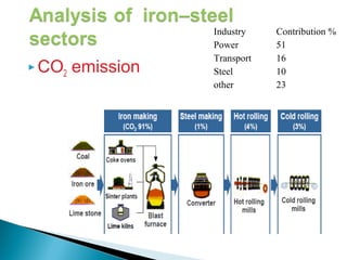
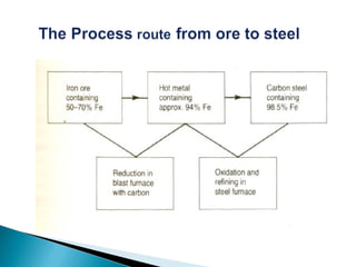
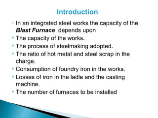
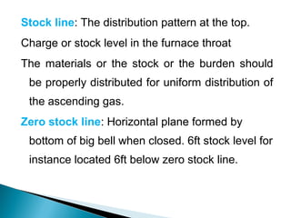
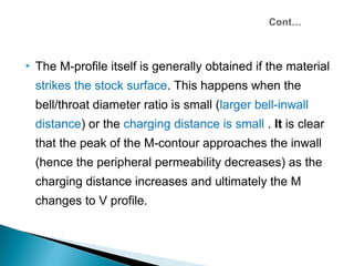
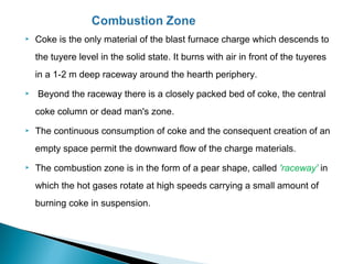
The document discusses key aspects of blast furnace design and operation, including:
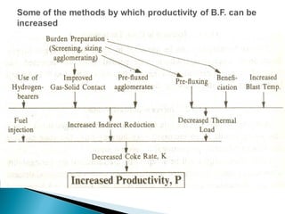
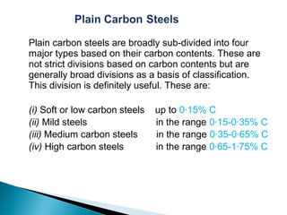
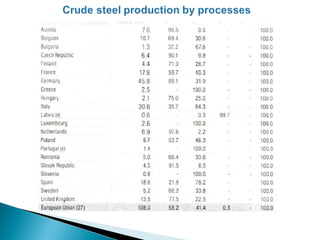
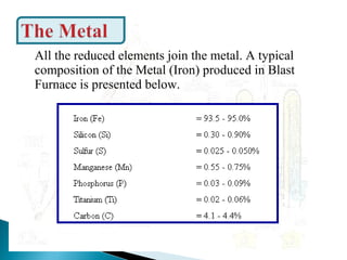
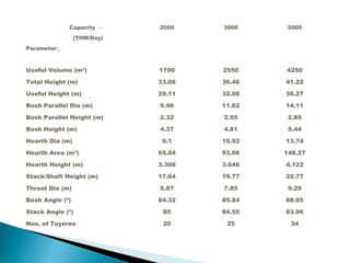
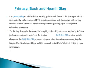
1. Blast furnace productivity depends on optimal gas flow and smooth, rapid burden descent which requires an optimized furnace profile and lines.
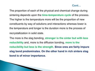
2. Effluent gas from the furnace contains 20-30% CO by volume and is cleaned through three stages before use to reduce dust from 7-30 g/m3 to 0.01 g/m3.
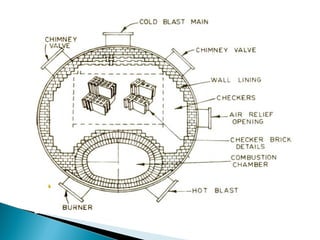
3. Stoves are used to heat incoming blast with heat from cleaned furnace gas in a cyclic process, maintaining a steady, preheated blast supply to the furnace.


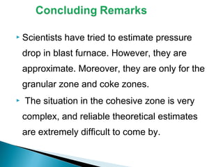
![
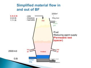
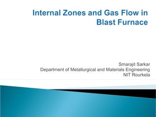
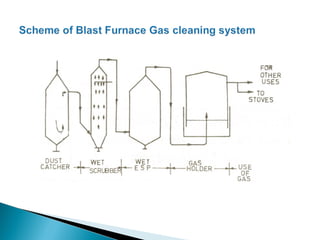
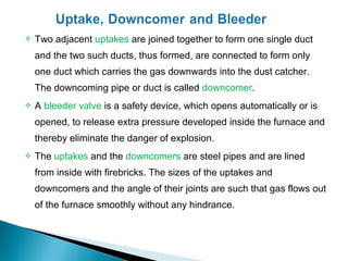
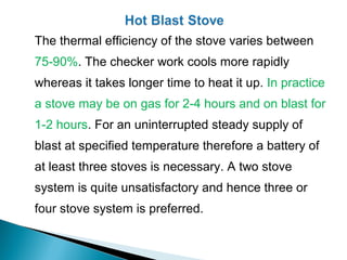
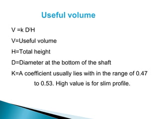
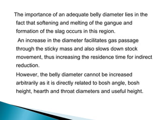
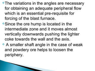
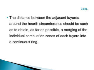
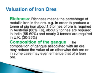
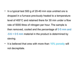
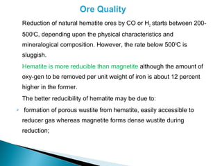
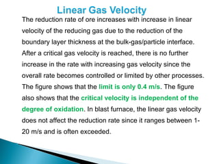
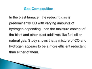
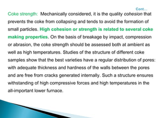
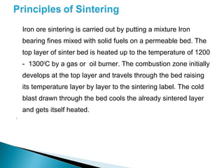
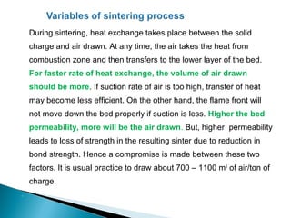
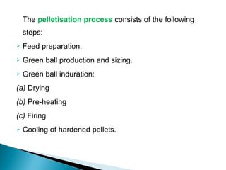
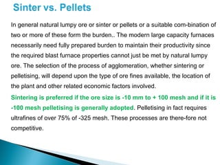
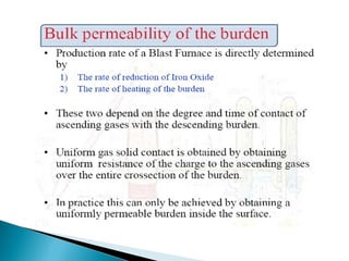
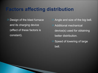
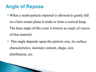
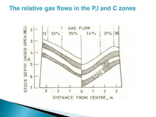
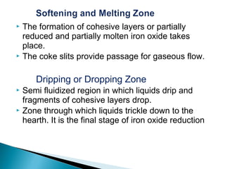
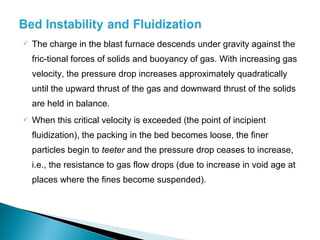
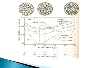
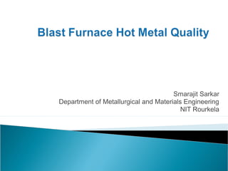
Further down the furnace, impure liquid iron and liquid slag are
formed. The absorption of carbon lowers the melting point of iron
drastically. For example, an iron alloy containing 4 wt. % carbon
melts at only 1185°C..
In the cohesive zone and below it, coke is the source of carbon for
carburisation of liquid iron. However, carbon directly does not
dissolve in liquid iron at this stage. The possible mechanism of
carburisation of iron entails the formation of CO by gasification of
carbon, followed by the absorption of carbon by the reaction:
2CO(g) = [C]in Fe+ CO2(g)](https://image.slidesharecdn.com/ironmaking-130302105459-phpapp02/85/Iron-making-159-320.jpg)
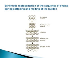
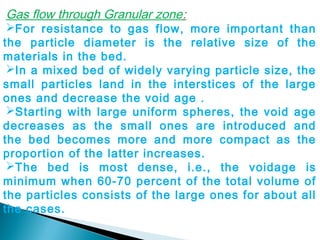
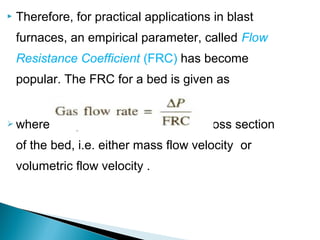
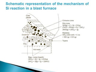
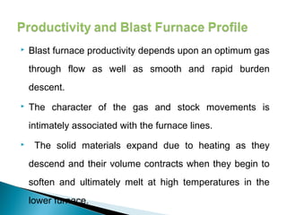
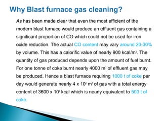
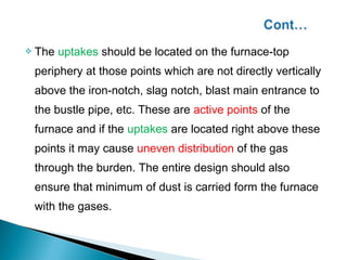
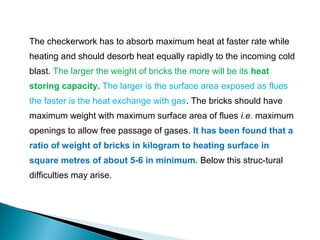
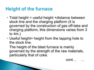
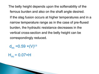
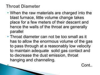
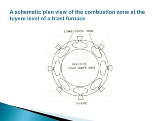
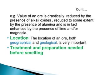
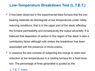
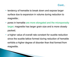
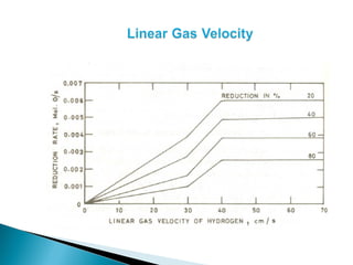
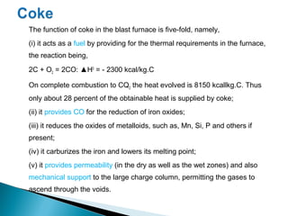
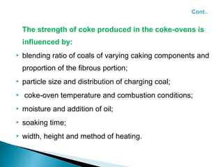
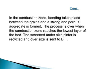
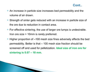
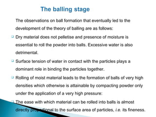
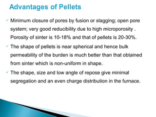
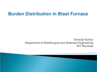
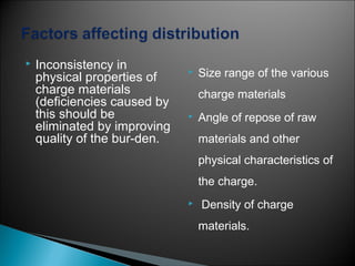
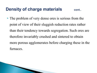
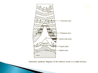
![ Desulphurisation of metal droplets through slag-
metal reaction in the furnace hearth :
(CaO) + [S] + [C ]= (CaS) + CO (g)
Desulphurisation through the coupled reaction:
(CaO) +[S] +[ Mn] = (CaS) + (MnO)
(CaO) + [S] + ½[ Si] = (CaS) + 1/2 (SiO2)](https://image.slidesharecdn.com/ironmaking-130302105459-phpapp02/85/Iron-making-197-320.jpg)
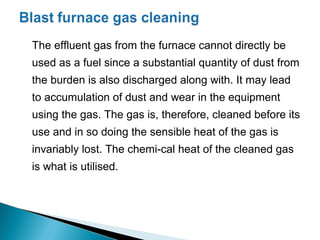
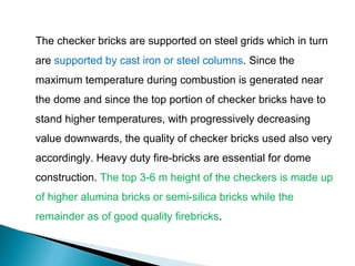
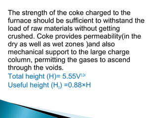
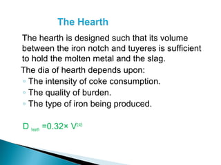
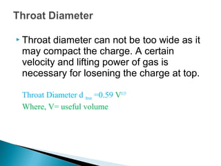
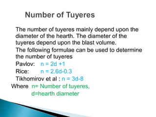
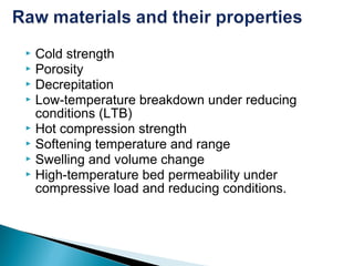
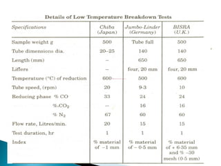
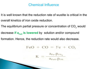
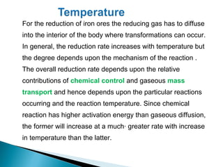
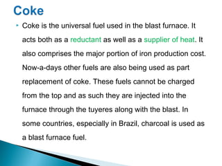
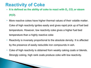
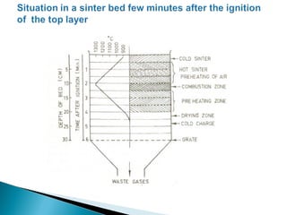
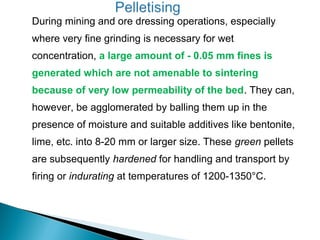
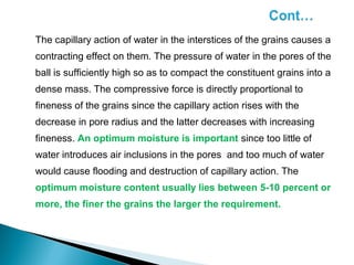
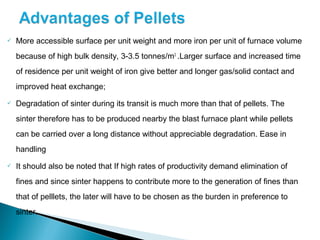
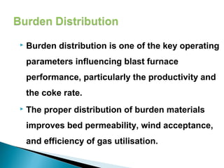
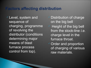
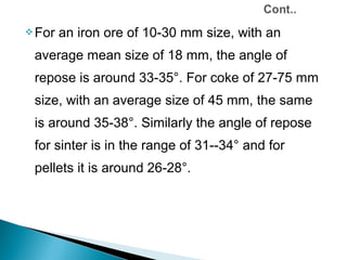
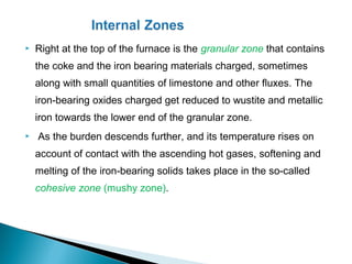
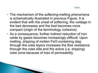
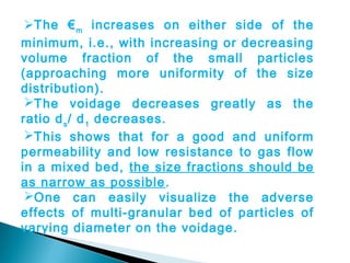
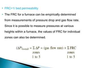
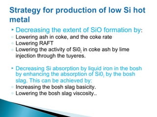
![ Sulphur pick-up through the vapour-
phase reaction:
CaS( in coke ash) + SiO (g) = SiS(g) +
CaO
FeS( in coke ash) + SiO (g) = SiS(g) +
CO(g) +[Fe]
In the bosh and belly regions, SiS
decomposes as
SiS(g) = [Si] + [S]](https://image.slidesharecdn.com/ironmaking-130302105459-phpapp02/85/Iron-making-198-320.jpg)