Downloaded 2,782 times

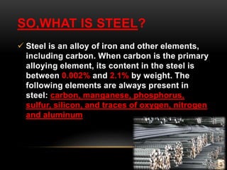
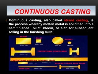
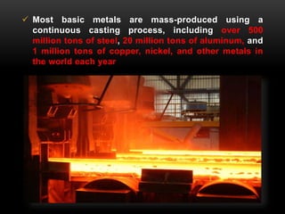
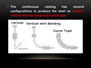
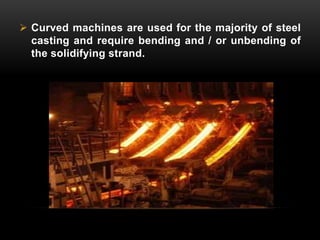
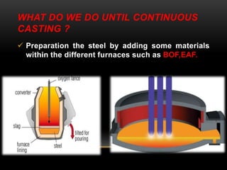
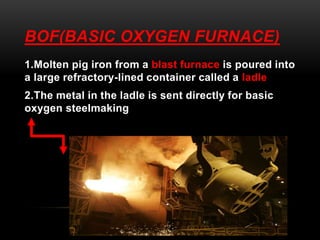
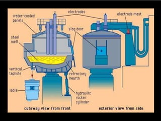
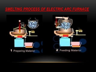
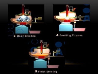
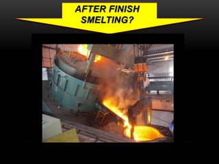
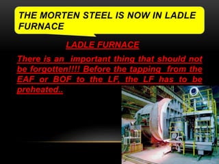
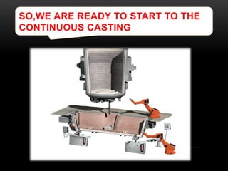
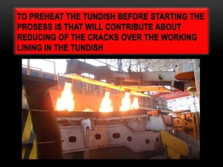
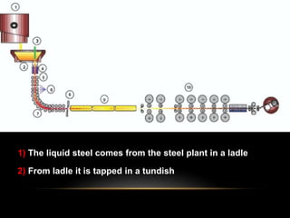
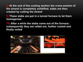
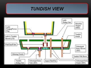
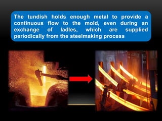
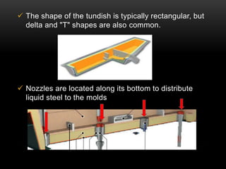
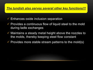
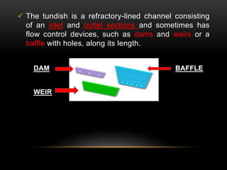
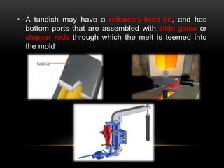
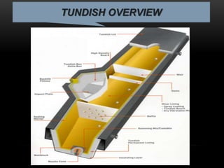
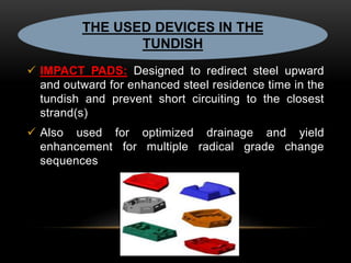
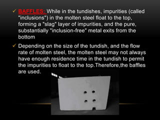
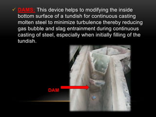
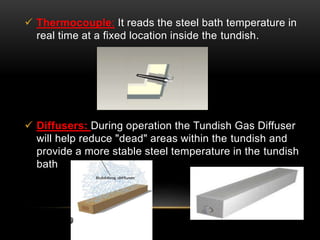
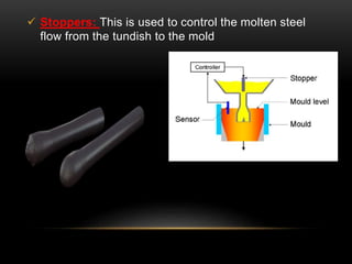
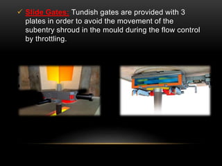
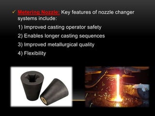
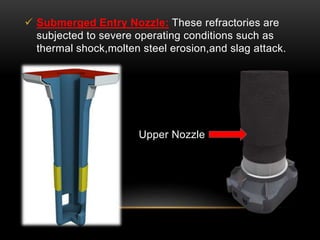
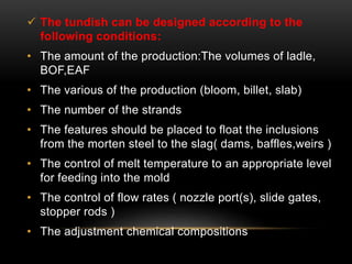
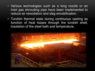
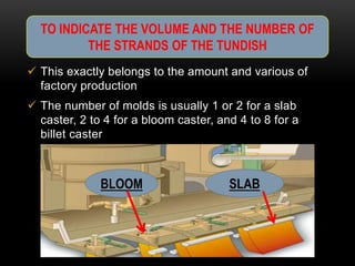
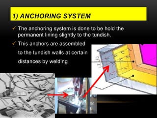
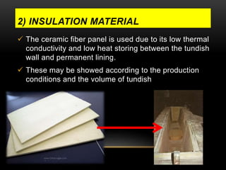
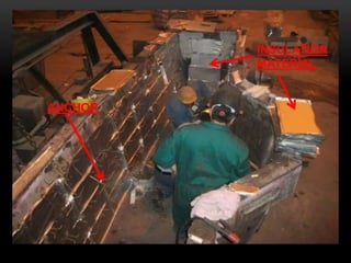
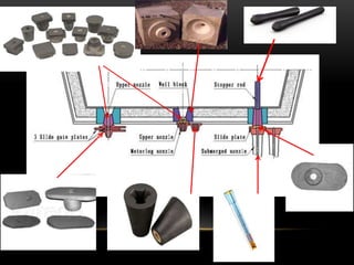
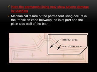
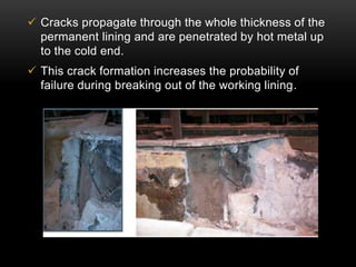

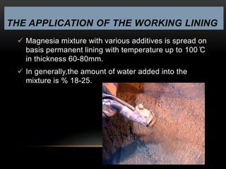
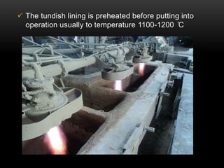
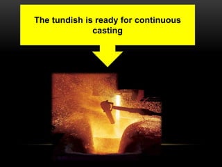

This document discusses the process of continuous casting of steel. It begins with an overview of steel composition and the continuous casting process, which solidifies molten metal directly into final form. Most metals are produced this way, including over 500 million tons of steel annually worldwide. The document then describes the steelmaking processes of basic oxygen furnaces and electric arc furnaces that prepare the molten steel. It focuses on the design, functions, and importance of tundishes in continuous casting, which hold molten steel and facilitate inclusion removal before casting. Key aspects of tundish design like features, insulation, nozzle placement, and refractory lining application are explained.


![BSP Project (Based on Continuous Casting) [Final]](https://cdn.slidesharecdn.com/ss_thumbnails/1cb7ea7d-f281-4d52-a9fa-9483a29f6fbc-150714213851-lva1-app6892-thumbnail.jpg?width=640&height=640&fit=bounds)