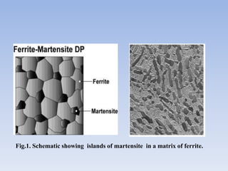
Metallurgical & Materials Engineering Department
NIT Warangal
DUAL PHASE STEEL AND TYPES OF WELDING
PERFORMED ON IT
Presented by -
Payal Priyadarshini
Roll no. - 175558
( Mtech 2nd yr) MT
DUAL PHASE STEELS
Introduction
What is dual Phase Steel?
• Dual Phase steels (DP) are part of the Advanced High Strength
Steels (AHSS) family.
• Composed of two phases: normally a ferrite matrix and a
dispersed second phase of martensite.
• The microstructure consists of a soft ferrite matrix containing
islands of martensite as the secondary phase which increases
the tensile strength.
Fig.1. Schematic showing islands of martensite in a matrix of ferrite.
EVOLUTION
• DP steels were developed in the 1970’s by British Iron and
Steel Research Association (BISRA, UK) and Inland Steel
Corporation.
• The development was driven by the need for new high strength
steels without reducing the formability or increasing costs
• Reason for this is the automotive industry has demanded steel
grades with high tensile elongation
• It ensure formability, high tensile strength to establish fatigue
and crash resistance, low alloy content to ensure weldability
without influencing production cost.
Composition of DP steels
• C - Austenite stabliser, strengthens the martensite, and
determines the phase distribution.
• Mn - Stablise the austenite and causes solid solution
strengthening in ferrite and retard ferrite formation.
• Cr & Mo - Retard pearlite or bainite formation,
• Si - Promotes ferrite transformation,
• V and Nb - Precipitation strengthening and microstructure
refinement.
MECHANICAL PROPERTIES OF DP
STEELS :
• Good combination of strength and ductility
• Absence of yield point phenomena
• Low yielding
• High initial work hardening rate
• High uniform and total elongation
• High strength to weight ratio
• Good formability
DIFFERENT GRADES OF DUAL PHASE
STEELS
Table.2. showing different grades of steel.
PROCESSINGS OF DP STEELS
• THERMOMECHANICAL ROLLING:
Fig.2. Schematic picture of layout of thermomechanical process
CONTINOUS ANNEALING IN
Α + ϒ RANGE:
• The major structural change that takes place
in continous anealing line is recrystalisation
and different phase transformation.
Fig.3. Schematic picture of layout of Continuous Annealing Line (CAL).
Fig.4. showing annealing cycle in CAL.
Fig.5. Production of dual phase steel by intercritical annealing. The
equilibrium fraction of austenite and ferriteas well as their carbon
content at the annealing temperature
DEVELOPMENT OF MICROSTRUCTURE
DURING PROCESSING
 FORMATION OF NEW FERRITE :
Fig.6. Formation of epitaxial or newferrite rim around austenite
particles after intercritical annealing and water quenching.
1=new ferrite (white), 2=retained ferrite (gray), 3=martensite (black).
• Before the water quenching of material in the
CAL, the strip passes through the gas-jet cooling
section .
• Consequently the temperature drop results in a
retransformation of austenite to ferrite, γ→α
• The new ferrite forms as a rim to the austenite, as
the austenite is in less developed state.
• retransformation of austenite depends upon the
amount and type of the austenite stabilizing
elements.
MARTENSITE FORMATION
• The austenite to martensite transformation is athermal
diffusionless transformation, occurring when the
austenite is cooled below the MS temperature.
• Since martensite formation is diffusionless, the carbon
atoms will be trapped in the octahedral sites of a bcc
structure.
• The solubility of carbon is greatly exceeded and
martensite assumes a body-centered tetragonal unit
cell, BCT, at sufficiently high carbon content.
• Martensite formation involves a shape change which
implies that plastic deformation of the austenite and
the surrounding ferrite phase.
DEFORMATION BEHAVIOR OF DP
STEELS
• Empirical Hollomon Equation,
σ (ε ) = K ⋅ εn
where, σ(ε) = true stress
ε = true plastic strain,
K = constant
And, n = strain hardening index.
• n is strain dependent, which means the slope of the log stress-
log strain curve for metallic alloys is not constant.
• These phenomena are often referred to as double-n or triple-n
behavior.
• Stress strain behavior is not satisfied for dual phase steel.
• Martensite transformation produce numerous
free mobile dislocations in the surrounding ferrite
matrix.
• Dislocation move with stresses much less than
that of required to move restrained dislocation.
• Dual phase steel yield plastic flow at lower
stresses of equivalent tensile strength.
• Martensite is the principal load bearing
constituent therefore volume percent of
martensite and steel strength are related linearly
to each other.
• Martensite strength can be increased by
decreasing the partical size.
Fig.7. stress-strain curve of different grain size dual steel
SECONDARY PROCESSINGS DONE ON
DUAL STEEL
Forming:
• DP can also be used to manufacture skin
parts, as a result of its excellent biaxial and
uniaxial stretch formability.
• Dual Phase steels can be drawn on
conventional tools, provided the settings are
properly adjusted.
• These steels, especially the highest grades,
are sensitive to the springback phenomenon
WELDING
• Although Dual Phase steels are more highly alloyed than
HSLA steels, they can be readily welded
• Using conventional resistance spot welding processes, DP
steels can be welded, provided the parameters used in
industrial conditions are adjusted.
• For small heat input and for achieving better property laser
welding is chosen.
APPLICATIONS OF DUAL PHASE STEEL
• Due to high energy absorption capacity and fatigue strength,
cold rolled Dual Phase Steels are well suited for automotive
structural and safety parts
• DP can be used to make visible parts with 20% higher dent
resistance than conventional high strength steels, resulting in a
potential weight saving of some 15%.
• Hot rolled Dual Phase can be used to reduce the weight of
structural parts by decreasing their thickness.
• The dual phase steels are used in automotive industry for
frames and crossbeams, vertical beams, side impact beams,
and safety elements
• Relevant automotive applications include Wheel
Webs,Longitudinal Rails,Shock Towers & Fasteners.
Fig.7. Uses of DP steels in automotive body parts
Fig.8. B-pillar
reinforcement in DP
Fig.9. Bumper
Fig.10. Wheel web in hot rolled Dual Phase
WELDING PERFORMED ON
DUAL PHASE STEELS
INTRODUCTION
• Dual-phase (DP) sheet steels have recently been used for
automotive manufacturing to reduce vehicle weight and
improve fuel economy.
• A good balance established between a ductile phase and hard
phase is lost during welding, because the fusion zone (FZ) and
heat-affect zone (HAZ) are rapidly cooled from the austenite
range.
• Generally DP steels presents a martensitic FZ and the HAZ
presents a softened region where the martensite is tempered.
TYPES OF WELDING USED FOR
DUAL PHASE STEELS
SPOT WELDING:
• Resistance spot welding is the primary joining process for
sheet steel in the auto body production.
• An electrical current passes through the joined sheets via
electrodes.
• A molten welding nugget is created by the heat induced
by the electrical current.
• The molten welding nugget grows until the electrical
current ceases, then the nugget solidifies to create a joint
between the sheets.
• The purpose of the resistance spot welding is to join
metals at surfaces that are made to fit together.
• Two resistance spot welding electrodes are used to
clamp sheets together during welding process.
• High levels of welding current, but at low voltage
pass through the joined metals.
• Then high temperatures are generated due to the high
electrical resistance between surfaces of joined
materials.
PROBLEMS ASSOCIATED WITH
RESISTANCE SPOT WELDING
• The risk of undesirable spot welds led to the
increasing of number of welds by approximately 20
%, which is time, energy and cost consumption.
• It is necessary to produce the quality spot welded
joints in terms of passengers` safety but Expulsion,
cracks, pores or voids negatively affect the weld
quality.
• When welding hot-dip galvanized steel sheets, the
zinc layer evaporates from the point of spot weld,
which lead to decreasing the corrosion resistance of
joined materials.
COMMONLY, THE WELD QUALITY
IS AFFECTED BY :
• The intensity of electrical current : for fixed electrode force
and welding time, when weld current increases to a certain
degree, it will cause severe expulsion and reduce the weld
strength.
• Electrode force: With the change of electrode force, the
width of weld lobe changes.
• Materials thicknesses: The spot weld strength increases with
increasing sheat thickness
• Welding time
• Electrode type and size.
MICROSTRUCTURALANALYSIS AFTER
RESISTANSE SPOT WELDING
Fig.11. Spot welded joint. Fig.12. Areas of spot weld
Fig.13. microstructure of weld metal
PRECAUTIONS TAKEN DURING
SPOT WELDING
• Electrode force should be increased somewhat compared to
what is normally used for mild steels.
• Weld time should be used slightly longer.
• It can be welded with both truncated cone and domed shaped
electrodes
LASER WELDING:
• Laser welding can be done for the dual phase steels, both
in the production of tailored welded blanks (TWB) ) and
for assembly welding.
• Small Heat Affected Zone (HAZ) and fusion zone (FZ),
the lower cost and greater flexibility compared to other
welding method.
• In laser welding, only a fraction of the incident beam
energy is actually absorbed by the workpiece, due to
reflection from the weld surface and transmission through
the keyhole.
• Therefore, the incident power of a laser beam
cannot be used directly in estimation of heat inputs or
thermal cycle shapes, and an alternate procedure has to be
employ.
• The top surfaces of the welding coupons were shielded
with high purity Ar.
• Welds were run with the lasers at full power, and heat
input was varied by changing welding speed.
• The microstructure is affected mainly by chemical
composition of base material, sheet thickness and weld
parameters such as power input, welding speed
PROBLEMS ASSOCIATED WITH
LASER WELDING
• Softening increases as welding speed is reduced, and at very
high welding speeds very little reduction in hardness occurs.
Fig.14. Min. hardness versus welding
Speed
• Amount of HAZ softening was directly proportional to
martensite content therefore plays a dominant role in
determining the maximum amount of HAZ softening when
laser welding DP steels.
Fig.15. Maximum amount of HAZ softening versus
martensite volume fraction
• High welding speed causes non-linear bead pool.
Fig.16. Microstructure of the bead pool of laser joint. Here v1Հ v2
MICROSTRUCTURAL ANALYSIS AFTER
LASER WELDING
Fig.17. Laser Welded Steel
Fig.18. Areas of HAZ
Fig.19. Areas of FZ

Dual phase steels (1)

  • 1.
    Metallurgical & MaterialsEngineering Department NIT Warangal DUAL PHASE STEEL AND TYPES OF WELDING PERFORMED ON IT Presented by - Payal Priyadarshini Roll no. - 175558 ( Mtech 2nd yr) MT
  • 2.
  • 3.
    Introduction What is dualPhase Steel? • Dual Phase steels (DP) are part of the Advanced High Strength Steels (AHSS) family. • Composed of two phases: normally a ferrite matrix and a dispersed second phase of martensite. • The microstructure consists of a soft ferrite matrix containing islands of martensite as the secondary phase which increases the tensile strength.
  • 4.
    Fig.1. Schematic showingislands of martensite in a matrix of ferrite.
  • 5.
    EVOLUTION • DP steelswere developed in the 1970’s by British Iron and Steel Research Association (BISRA, UK) and Inland Steel Corporation. • The development was driven by the need for new high strength steels without reducing the formability or increasing costs • Reason for this is the automotive industry has demanded steel grades with high tensile elongation • It ensure formability, high tensile strength to establish fatigue and crash resistance, low alloy content to ensure weldability without influencing production cost.
  • 6.
  • 7.
    • C -Austenite stabliser, strengthens the martensite, and determines the phase distribution. • Mn - Stablise the austenite and causes solid solution strengthening in ferrite and retard ferrite formation. • Cr & Mo - Retard pearlite or bainite formation, • Si - Promotes ferrite transformation, • V and Nb - Precipitation strengthening and microstructure refinement.
  • 8.
    MECHANICAL PROPERTIES OFDP STEELS : • Good combination of strength and ductility • Absence of yield point phenomena • Low yielding • High initial work hardening rate • High uniform and total elongation • High strength to weight ratio • Good formability
  • 9.
    DIFFERENT GRADES OFDUAL PHASE STEELS Table.2. showing different grades of steel.
  • 10.
    PROCESSINGS OF DPSTEELS • THERMOMECHANICAL ROLLING: Fig.2. Schematic picture of layout of thermomechanical process
  • 11.
    CONTINOUS ANNEALING IN Α+ ϒ RANGE: • The major structural change that takes place in continous anealing line is recrystalisation and different phase transformation. Fig.3. Schematic picture of layout of Continuous Annealing Line (CAL).
  • 12.
  • 13.
    Fig.5. Production ofdual phase steel by intercritical annealing. The equilibrium fraction of austenite and ferriteas well as their carbon content at the annealing temperature
  • 14.
    DEVELOPMENT OF MICROSTRUCTURE DURINGPROCESSING  FORMATION OF NEW FERRITE : Fig.6. Formation of epitaxial or newferrite rim around austenite particles after intercritical annealing and water quenching. 1=new ferrite (white), 2=retained ferrite (gray), 3=martensite (black).
  • 15.
    • Before thewater quenching of material in the CAL, the strip passes through the gas-jet cooling section . • Consequently the temperature drop results in a retransformation of austenite to ferrite, γ→α • The new ferrite forms as a rim to the austenite, as the austenite is in less developed state. • retransformation of austenite depends upon the amount and type of the austenite stabilizing elements.
  • 16.
    MARTENSITE FORMATION • Theaustenite to martensite transformation is athermal diffusionless transformation, occurring when the austenite is cooled below the MS temperature. • Since martensite formation is diffusionless, the carbon atoms will be trapped in the octahedral sites of a bcc structure. • The solubility of carbon is greatly exceeded and martensite assumes a body-centered tetragonal unit cell, BCT, at sufficiently high carbon content. • Martensite formation involves a shape change which implies that plastic deformation of the austenite and the surrounding ferrite phase.
  • 17.
    DEFORMATION BEHAVIOR OFDP STEELS • Empirical Hollomon Equation, σ (ε ) = K ⋅ εn where, σ(ε) = true stress ε = true plastic strain, K = constant And, n = strain hardening index. • n is strain dependent, which means the slope of the log stress- log strain curve for metallic alloys is not constant. • These phenomena are often referred to as double-n or triple-n behavior. • Stress strain behavior is not satisfied for dual phase steel.
  • 18.
    • Martensite transformationproduce numerous free mobile dislocations in the surrounding ferrite matrix. • Dislocation move with stresses much less than that of required to move restrained dislocation. • Dual phase steel yield plastic flow at lower stresses of equivalent tensile strength. • Martensite is the principal load bearing constituent therefore volume percent of martensite and steel strength are related linearly to each other. • Martensite strength can be increased by decreasing the partical size.
  • 19.
    Fig.7. stress-strain curveof different grain size dual steel
  • 20.
    SECONDARY PROCESSINGS DONEON DUAL STEEL Forming: • DP can also be used to manufacture skin parts, as a result of its excellent biaxial and uniaxial stretch formability. • Dual Phase steels can be drawn on conventional tools, provided the settings are properly adjusted. • These steels, especially the highest grades, are sensitive to the springback phenomenon
  • 21.
    WELDING • Although DualPhase steels are more highly alloyed than HSLA steels, they can be readily welded • Using conventional resistance spot welding processes, DP steels can be welded, provided the parameters used in industrial conditions are adjusted. • For small heat input and for achieving better property laser welding is chosen.
  • 22.
    APPLICATIONS OF DUALPHASE STEEL • Due to high energy absorption capacity and fatigue strength, cold rolled Dual Phase Steels are well suited for automotive structural and safety parts • DP can be used to make visible parts with 20% higher dent resistance than conventional high strength steels, resulting in a potential weight saving of some 15%. • Hot rolled Dual Phase can be used to reduce the weight of structural parts by decreasing their thickness. • The dual phase steels are used in automotive industry for frames and crossbeams, vertical beams, side impact beams, and safety elements
  • 23.
    • Relevant automotiveapplications include Wheel Webs,Longitudinal Rails,Shock Towers & Fasteners. Fig.7. Uses of DP steels in automotive body parts Fig.8. B-pillar reinforcement in DP
  • 24.
    Fig.9. Bumper Fig.10. Wheelweb in hot rolled Dual Phase
  • 25.
    WELDING PERFORMED ON DUALPHASE STEELS INTRODUCTION • Dual-phase (DP) sheet steels have recently been used for automotive manufacturing to reduce vehicle weight and improve fuel economy. • A good balance established between a ductile phase and hard phase is lost during welding, because the fusion zone (FZ) and heat-affect zone (HAZ) are rapidly cooled from the austenite range. • Generally DP steels presents a martensitic FZ and the HAZ presents a softened region where the martensite is tempered.
  • 26.
    TYPES OF WELDINGUSED FOR DUAL PHASE STEELS SPOT WELDING: • Resistance spot welding is the primary joining process for sheet steel in the auto body production. • An electrical current passes through the joined sheets via electrodes. • A molten welding nugget is created by the heat induced by the electrical current. • The molten welding nugget grows until the electrical current ceases, then the nugget solidifies to create a joint between the sheets.
  • 27.
    • The purposeof the resistance spot welding is to join metals at surfaces that are made to fit together. • Two resistance spot welding electrodes are used to clamp sheets together during welding process. • High levels of welding current, but at low voltage pass through the joined metals. • Then high temperatures are generated due to the high electrical resistance between surfaces of joined materials.
  • 28.
    PROBLEMS ASSOCIATED WITH RESISTANCESPOT WELDING • The risk of undesirable spot welds led to the increasing of number of welds by approximately 20 %, which is time, energy and cost consumption. • It is necessary to produce the quality spot welded joints in terms of passengers` safety but Expulsion, cracks, pores or voids negatively affect the weld quality. • When welding hot-dip galvanized steel sheets, the zinc layer evaporates from the point of spot weld, which lead to decreasing the corrosion resistance of joined materials.
  • 29.
    COMMONLY, THE WELDQUALITY IS AFFECTED BY : • The intensity of electrical current : for fixed electrode force and welding time, when weld current increases to a certain degree, it will cause severe expulsion and reduce the weld strength. • Electrode force: With the change of electrode force, the width of weld lobe changes. • Materials thicknesses: The spot weld strength increases with increasing sheat thickness • Welding time • Electrode type and size.
  • 30.
    MICROSTRUCTURALANALYSIS AFTER RESISTANSE SPOTWELDING Fig.11. Spot welded joint. Fig.12. Areas of spot weld Fig.13. microstructure of weld metal
  • 31.
    PRECAUTIONS TAKEN DURING SPOTWELDING • Electrode force should be increased somewhat compared to what is normally used for mild steels. • Weld time should be used slightly longer. • It can be welded with both truncated cone and domed shaped electrodes
  • 32.
    LASER WELDING: • Laserwelding can be done for the dual phase steels, both in the production of tailored welded blanks (TWB) ) and for assembly welding. • Small Heat Affected Zone (HAZ) and fusion zone (FZ), the lower cost and greater flexibility compared to other welding method. • In laser welding, only a fraction of the incident beam energy is actually absorbed by the workpiece, due to reflection from the weld surface and transmission through the keyhole.
  • 33.
    • Therefore, theincident power of a laser beam cannot be used directly in estimation of heat inputs or thermal cycle shapes, and an alternate procedure has to be employ. • The top surfaces of the welding coupons were shielded with high purity Ar. • Welds were run with the lasers at full power, and heat input was varied by changing welding speed. • The microstructure is affected mainly by chemical composition of base material, sheet thickness and weld parameters such as power input, welding speed
  • 34.
    PROBLEMS ASSOCIATED WITH LASERWELDING • Softening increases as welding speed is reduced, and at very high welding speeds very little reduction in hardness occurs. Fig.14. Min. hardness versus welding Speed
  • 35.
    • Amount ofHAZ softening was directly proportional to martensite content therefore plays a dominant role in determining the maximum amount of HAZ softening when laser welding DP steels. Fig.15. Maximum amount of HAZ softening versus martensite volume fraction
  • 36.
    • High weldingspeed causes non-linear bead pool. Fig.16. Microstructure of the bead pool of laser joint. Here v1Հ v2
  • 37.
    MICROSTRUCTURAL ANALYSIS AFTER LASERWELDING Fig.17. Laser Welded Steel
  • 38.
  • 39.