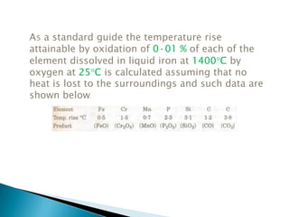
Downloaded 217 times

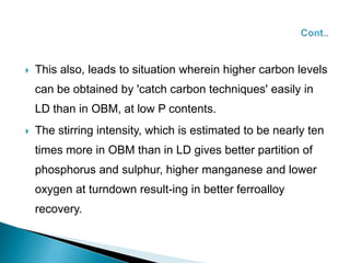
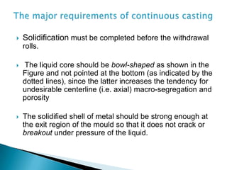
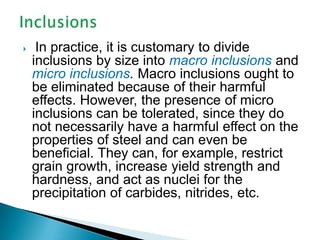
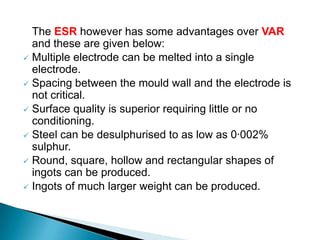
![Better mixing and homogeneity in the bath offer the following
advantages:
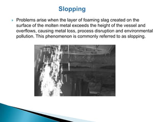
Less slopping, since non-homogeneity causes formation of
regions with high supersaturation and consequent violent
reactions and ejections.
Better mixing and mass transfer in the metal bath with closer
approach to equilibrium for [C]-[O]-CO reaction, and
consequently, lower bath oxygen content at the same carbon
content](https://image.slidesharecdn.com/ainsm-130211132918-phpapp01/85/Ainsm-13-320.jpg)
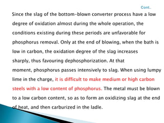
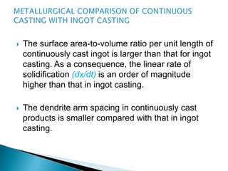
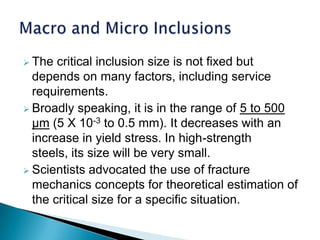
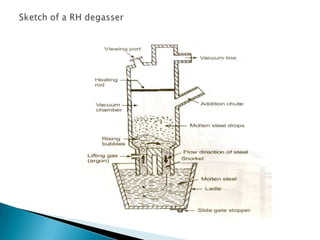
![ If the metal is tapped and teemed without being deoxidized, the reaction
[O] + [C] = COg will take place between the dissolved oxygen and
carbon as the metal is cooled slowly in the mould. Bubbles of carbon
monoxide evolve from the solidifying metal, agitate the metal in the
mould vigorously, and the metal surface is seen to 'boil'. Such steel is
called 'wild'; when solidified, it will be termed 'rimming steel' .
In some cases, only partial deoxidation is carried out, i.e. oxygen is only
partially removed from the metal. The remaining dissolved oxygen
causes the metal to boil for a short time. This type of steel is termed
'semi-killed'.](https://image.slidesharecdn.com/ainsm-130211132918-phpapp01/85/Ainsm-24-320.jpg)

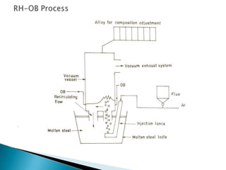
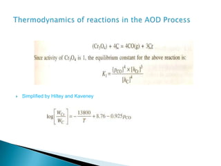
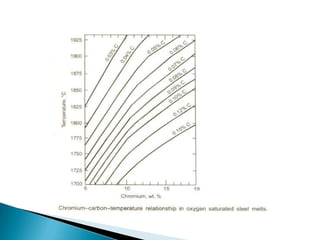
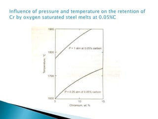


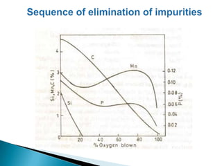
The document discusses hybrid blowing in steelmaking. Hybrid blowing involves blowing a portion of oxygen from the bottom of the vessel along with blowing from the top. Blowing oxygen from the bottom improves mixing and homogeneity in the bath, reduces slopping, and leads the process closer to equilibrium, improving dephosphorization and desulphurization abilities. Compared to top blowing or bottom blowing alone, hybrid blowing provides benefits such as improved control, reduced over-oxidation, and higher yields.


