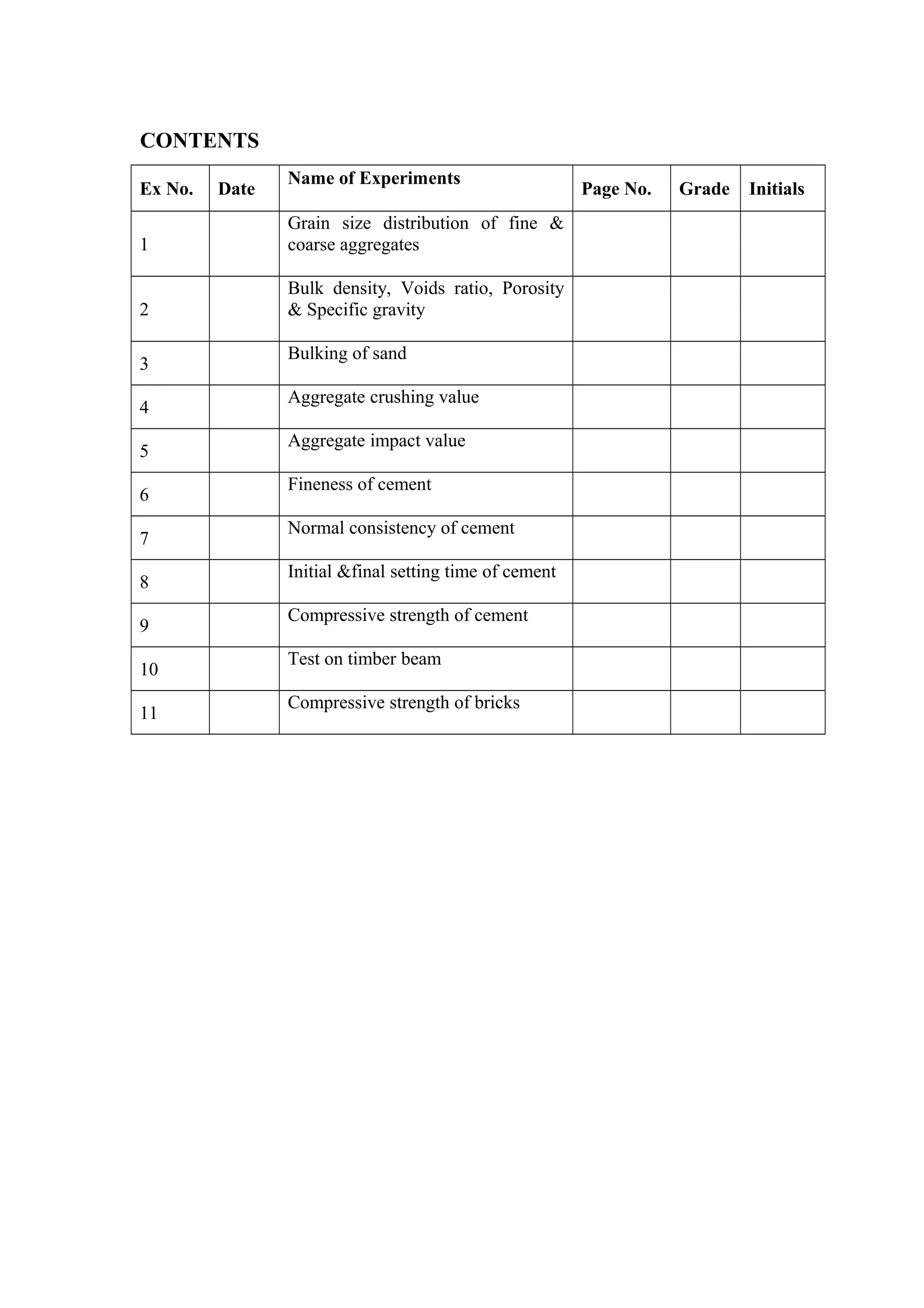
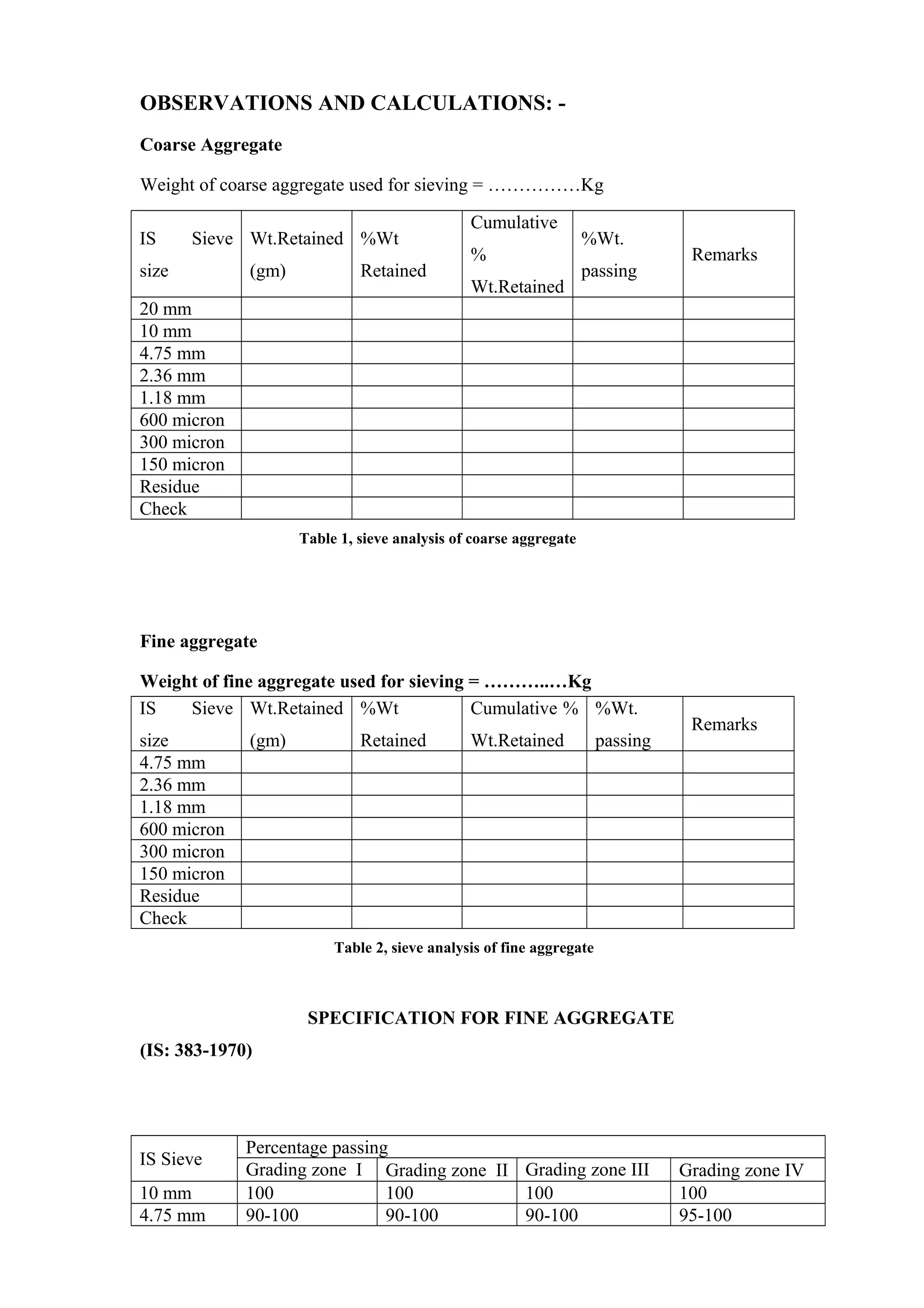
This document provides information on procedures to determine various properties of aggregates through laboratory experiments. It describes 12 experiments related to grain size distribution, bulk density, voids ratio, porosity, specific gravity, bulking, crushing value, impact value, and compressive strength of aggregates and cement. The summary focuses on Experiment 1 which involves determining the particle size distribution of fine and coarse aggregates through sieve analysis.
Strength of concrete (for civil engineering) laxman singh
i have made all the slide for civil engineering and poly diploma civil.
these are 100% correct but in case of some error comment down or contact me on (laxmans227@gmail.com)
follow me for all updates
if u have any doubt fell free to ask on comment section
i upload new slides every sunday,
so keep calm and follow me(now).
software - power point presentation 2015
High volume fly ash concrete is a concrete where a replacement of about 35% or more of cement is made with the usage of fly ash.
Fly ash concrete is an eco-friendly construction material in which fly ash replaces a part of Portland cement.
قازانج و خراپییەکانی کۆنکریت
Concrete is a composite material composed of coarse aggregate bonded together with a fluid cement that hardens over time. Most concretes used are lime-based concretes such as Portland cement concrete or concretes made with other hydraulic cements, such as ciment fondu. However, asphalt concrete, which is frequently used for road surfaces, is also a type of concrete, where the cement material is bitumen, and polymer concretes are sometimes used where the cementing material is a polymer.
When aggregate is mixed together with dry Portland cement and water, the mixture forms a fluid mass that is easily molded into shape. The cement reacts chemically with the water and other ingredients to form a hard matrix that binds the materials together into a durable stone-like material that has many uses.[2] Often, additives (such as pozzolans or superplasticizers) are included in the mixture to improve the physical properties of the wet mix or the finished material. Most concrete is poured with reinforcing materials (such as rebar) embedded to provide tensile strength, yielding reinforced concrete.
Famous concrete structures include the Hoover Dam, the Panama Canal, and the Roman Pantheon. The earliest large-scale users of concrete technology were the ancient Romans, and concrete was widely used in the Roman Empire. The Colosseum in Rome was built largely of concrete, and the concrete dome of the Pantheon is the world's largest unreinforced concrete dome.[3] Today, large concrete structures (for example, dams and multi-storey car parks) are usually made with reinforced concrete.
After the Roman Empire collapsed, use of concrete became rare until the technology was redeveloped in the mid-18th century. Today, concrete is the most widely used man-made material (measured by tonnage).
a brief research about permeability & durability of concrete with helpful images for civil engineering students
fully made by Amira Abdullah (civil engineering student in Ismailia - Egypt)
Soil nailing is a technique used to reinforce and strengthen existing ground.Soil nailing consists of installing closely spaced bars into a slope or excavation as construction proceeds from top down.It is an effective and economical method of constructing retaining wall for excavation support, support of hill cuts, bridge abutments and high ways.This process is effective in cohesive soil, broken rock, shale or fixed face conditions.
Permeability of concrete, chemical attack, acid attack, efflorescence, Corrosion in concrete. Thermal conductivity, thermal diffusivity, specific heat. Alkali Aggregate Reaction
A review on different destructive methods to determine the compressive streng...IJERD Editor
Determination of the compressive strength of an existing masonry attracted the attention of many scientists and researchers around the world. Most of these researchers, scientists and engineers want to find the best way to obtain the compressive strength of masonry in situ with high accuracy, and less cost. There are many methods to determine the compressive strength of masonry. Some of these methods are destructive methods and others are non-destructive methods and others are partially destructive. Each one of these testing methods has advantages and disadvantages .this paper presents different destructive testing Methodsfor obtaining the compressive strength of an existing masonry. Testing procedure, the main advantages and the problems of each method are explored.
Alpha Engineering Equipments was established in 1992. We are a leading trader, supplier and exporter of Surveying and Testing Equipment in Nagpur. Our range finds extensive application in accurately identifying angles, elevation and direction, and assessing bitumen, cement and soil. Apart from these, the range can also be used to test metals, concrete, tar, fuel, rubber, leather.
Concrete is made up of ingredients like Cement, Fine Aggregate (Sand), Coarse Aggregate, Water and admixtures. Concrete mix design is done to Optimize the requirements of Cement, Sand, Aggregate and Water in order to ensure that concrete parameters in both Plastic Stage (like workability) and in Hardened Stage (like Compressive Strength and durability) are achieved. The Concrete mix design is as per Indian Standards (IS 10262) and might vary from country to country. The nominal mix design ratios available for concrete less than M30 in strength are only thumb rules and are generally over designed. As the actual site conditions vary and the mix design should be adjusted as per the location and other factors.
The report is being made on the experience of 3 weeks office training.
briefly describes the quality tests of Fine and Coarse aggregates .
Complete calculation of concrete mix design is included with solved numerical equations.
Cement, water and admixtures quality test is not performed because the contractor purchase it from other chemical and cement manufacturer company.
A summer training presentation on Highway material and soil testing.
In this presentation along with the entire test procedure readings and images of apparatus are used for better understanding.
The experiments are presented in a creative manner.
index properties of soil, Those properties of soil which are used in the identification and classification of soil are known as INDEX PROPERTIES
Water content
Specific gravity
In-situ density
Particle size
Consistency
Relative Density
About
Indigenized remote control interface card suitable for MAFI system CCR equipment. Compatible for IDM8000 CCR. Backplane mounted serial and TCP/Ethernet communication module for CCR remote access. IDM 8000 CCR remote control on serial and TCP protocol.
• Remote control: Parallel or serial interface.
• Compatible with MAFI CCR system.
• Compatible with IDM8000 CCR.
• Compatible with Backplane mount serial communication.
• Compatible with commercial and Defence aviation CCR system.
• Remote control system for accessing CCR and allied system over serial or TCP.
• Indigenized local Support/presence in India.
• Easy in configuration using DIP switches.
Technical Specifications
Indigenized remote control interface card suitable for MAFI system CCR equipment. Compatible for IDM8000 CCR. Backplane mounted serial and TCP/Ethernet communication module for CCR remote access. IDM 8000 CCR remote control on serial and TCP protocol.
Key Features
Indigenized remote control interface card suitable for MAFI system CCR equipment. Compatible for IDM8000 CCR. Backplane mounted serial and TCP/Ethernet communication module for CCR remote access. IDM 8000 CCR remote control on serial and TCP protocol.
• Remote control: Parallel or serial interface
• Compatible with MAFI CCR system
• Copatiable with IDM8000 CCR
• Compatible with Backplane mount serial communication.
• Compatible with commercial and Defence aviation CCR system.
• Remote control system for accessing CCR and allied system over serial or TCP.
• Indigenized local Support/presence in India.
Application
• Remote control: Parallel or serial interface.
• Compatible with MAFI CCR system.
• Compatible with IDM8000 CCR.
• Compatible with Backplane mount serial communication.
• Compatible with commercial and Defence aviation CCR system.
• Remote control system for accessing CCR and allied system over serial or TCP.
• Indigenized local Support/presence in India.
• Easy in configuration using DIP switches.
Student information management system project report ii.pdfKamal Acharya
Our project explains about the student management. This project mainly explains the various actions related to student details. This project shows some ease in adding, editing and deleting the student details. It also provides a less time consuming process for viewing, adding, editing and deleting the marks of the students.
NO1 Uk best vashikaran specialist in delhi vashikaran baba near me online vas...Amil Baba Dawood bangali
Contact with Dawood Bhai Just call on +92322-6382012 and we'll help you. We'll solve all your problems within 12 to 24 hours and with 101% guarantee and with astrology systematic. If you want to take any personal or professional advice then also you can call us on +92322-6382012 , ONLINE LOVE PROBLEM & Other all types of Daily Life Problem's.Then CALL or WHATSAPP us on +92322-6382012 and Get all these problems solutions here by Amil Baba DAWOOD BANGALI
#vashikaranspecialist #astrologer #palmistry #amliyaat #taweez #manpasandshadi #horoscope #spiritual #lovelife #lovespell #marriagespell#aamilbabainpakistan #amilbabainkarachi #powerfullblackmagicspell #kalajadumantarspecialist #realamilbaba #AmilbabainPakistan #astrologerincanada #astrologerindubai #lovespellsmaster #kalajaduspecialist #lovespellsthatwork #aamilbabainlahore#blackmagicformarriage #aamilbaba #kalajadu #kalailam #taweez #wazifaexpert #jadumantar #vashikaranspecialist #astrologer #palmistry #amliyaat #taweez #manpasandshadi #horoscope #spiritual #lovelife #lovespell #marriagespell#aamilbabainpakistan #amilbabainkarachi #powerfullblackmagicspell #kalajadumantarspecialist #realamilbaba #AmilbabainPakistan #astrologerincanada #astrologerindubai #lovespellsmaster #kalajaduspecialist #lovespellsthatwork #aamilbabainlahore #blackmagicforlove #blackmagicformarriage #aamilbaba #kalajadu #kalailam #taweez #wazifaexpert #jadumantar #vashikaranspecialist #astrologer #palmistry #amliyaat #taweez #manpasandshadi #horoscope #spiritual #lovelife #lovespell #marriagespell#aamilbabainpakistan #amilbabainkarachi #powerfullblackmagicspell #kalajadumantarspecialist #realamilbaba #AmilbabainPakistan #astrologerincanada #astrologerindubai #lovespellsmaster #kalajaduspecialist #lovespellsthatwork #aamilbabainlahore #Amilbabainuk #amilbabainspain #amilbabaindubai #Amilbabainnorway #amilbabainkrachi #amilbabainlahore #amilbabaingujranwalan #amilbabainislamabad
Hybrid optimization of pumped hydro system and solar- Engr. Abdul-Azeez.pdffxintegritypublishin
Advancements in technology unveil a myriad of electrical and electronic breakthroughs geared towards efficiently harnessing limited resources to meet human energy demands. The optimization of hybrid solar PV panels and pumped hydro energy supply systems plays a pivotal role in utilizing natural resources effectively. This initiative not only benefits humanity but also fosters environmental sustainability. The study investigated the design optimization of these hybrid systems, focusing on understanding solar radiation patterns, identifying geographical influences on solar radiation, formulating a mathematical model for system optimization, and determining the optimal configuration of PV panels and pumped hydro storage. Through a comparative analysis approach and eight weeks of data collection, the study addressed key research questions related to solar radiation patterns and optimal system design. The findings highlighted regions with heightened solar radiation levels, showcasing substantial potential for power generation and emphasizing the system's efficiency. Optimizing system design significantly boosted power generation, promoted renewable energy utilization, and enhanced energy storage capacity. The study underscored the benefits of optimizing hybrid solar PV panels and pumped hydro energy supply systems for sustainable energy usage. Optimizing the design of solar PV panels and pumped hydro energy supply systems as examined across diverse climatic conditions in a developing country, not only enhances power generation but also improves the integration of renewable energy sources and boosts energy storage capacities, particularly beneficial for less economically prosperous regions. Additionally, the study provides valuable insights for advancing energy research in economically viable areas. Recommendations included conducting site-specific assessments, utilizing advanced modeling tools, implementing regular maintenance protocols, and enhancing communication among system components.
Explore the innovative world of trenchless pipe repair with our comprehensive guide, "The Benefits and Techniques of Trenchless Pipe Repair." This document delves into the modern methods of repairing underground pipes without the need for extensive excavation, highlighting the numerous advantages and the latest techniques used in the industry.
Learn about the cost savings, reduced environmental impact, and minimal disruption associated with trenchless technology. Discover detailed explanations of popular techniques such as pipe bursting, cured-in-place pipe (CIPP) lining, and directional drilling. Understand how these methods can be applied to various types of infrastructure, from residential plumbing to large-scale municipal systems.
Ideal for homeowners, contractors, engineers, and anyone interested in modern plumbing solutions, this guide provides valuable insights into why trenchless pipe repair is becoming the preferred choice for pipe rehabilitation. Stay informed about the latest advancements and best practices in the field.
The Benefits and Techniques of Trenchless Pipe Repair.pdf
Concrete lab s5
1. CONTENTS
Ex No. Date
Name of Experiments
Page No. Grade Initials
1
Grain size distribution of fine &
coarse aggregates
2
Bulk density, Voids ratio, Porosity
& Specific gravity
3
Bulking of sand
4
Aggregate crushing value
5
Aggregate impact value
6
Fineness of cement
7
Normal consistency of cement
8
Initial &final setting time of cement
9
Compressive strength of cement
10
Test on timber beam
11
Compressive strength of bricks
2. GRAIN SIZE DISTRIBUTION OF FINE &
COARSE AGGREGATES
Experiment No: 1
Date:
AIM:
To determine the particle size distribution of fine and coarse aggregates.
GENERAL:
The aggregate most of which passes IS: 4.75 mm sieve is classified as fine
aggregate. The fine aggregates obtained from natural disintegration of rocks and
deposited by streams are known as natural sands. Fine aggregates resulting from
crushing of hard stone are known as crushed sand.
The aggregate most of which is retained on IS 4.75 mm sieve is classified as
coarse aggregate. This may be in the form of uncrushed gravel or stone resulting from
natural disintegration of rocks. Crushed gravel or stone is obtained by crushed gravel or
hard stone.
Sieve analysis is carried out for the determination of fine and coarse aggregates
by sieving or screening. Sieves of size 80 mm, 40mm, 20mm, 10 mm, 4.75 mm, 2.36
mm, 1.18 mm, 600 micron, 300 micron &150 micron confirming to IS: 460.
APPARATUS:
a) Balance: -The balance shall be such that it is readable and accurate to 0.1% of
the weight of the test sample.
b) Sieves:- sieves of the sizes given in table 1 & 2 confirming to
IS: 460-1962 shall be used.
3. PROCEDURE:
Take 1 kg of air-dry sample of the fine aggregate (2 kg of coarse aggregate) and sieve
successively on the appropriate sieves starting with the largest. Care shall be taken to
ensure that the sieves are clean before use. Each sieve shall be taken separately over a
clear tray until not more than a trace passes, but in any case for a period of not less than
2 minutes. If a mechanical sieve shaker is used, arrange the set of sieves in the order of
their aperture sizes in such a way that the sieve having smallest opening comes at the
bottom and a minimum of 10 minutes sieving will be required. Weigh the aggregate
retained in each sieve . Draw a graph taking logarithm (Log 10 ) of aperture size of the
sieve on the X-axis and % finer on the Y-axis.
Reporting of results: -
The result shall be calculated and reported as follows
The sieve opening corresponding to 10% passing (D10) gives effective size.
The ratio of sieve opening corresponding to 60% (D60) to sieve opening
corresponding to 10% passing (D10) gives uniformity coefficient.
The sum of the cumulative % retained in each of the sieves divided by 100 gives the
fineness modulus of the aggregate.
Grading zone can be determined by plotting a graph with logarithm of aperture size
of the sieves versus % finer according to value given in table 3.
4. OBSERVATIONS AND CALCULATIONS: -
Coarse Aggregate
Weight of coarse aggregate used for sieving = ……………Kg
IS Sieve
size
Wt.Retained
(gm)
%Wt
Retained
Cumulative
%
Wt.Retained
%Wt.
passing
Remarks
20 mm
10 mm
4.75 mm
2.36 mm
1.18 mm
600 micron
300 micron
150 micron
Residue
Check
Table 1, sieve analysis of coarse aggregate
Fine aggregate
Weight of fine aggregate used for sieving = ………..…Kg
IS Sieve
size
Wt.Retained
(gm)
%Wt
Retained
Cumulative %
Wt.Retained
%Wt.
passing
Remarks
4.75 mm
2.36 mm
1.18 mm
600 micron
300 micron
150 micron
Residue
Check
Table 2, sieve analysis of fine aggregate
SPECIFICATION FOR FINE AGGREGATE
(IS: 383-1970)
IS Sieve
Percentage passing
Grading zone I Grading zone II Grading zone III Grading zone IV
10 mm 100 100 100 100
4.75 mm 90-100 90-100 90-100 95-100
5. 2.36 mm 60-95 75-100 85-100 95-100
1.18 mm 30-70 55-90 75-100 90-100
600 micron 15-34 35-59 60-79 80-100
300 micron 05-20 08-30 12-40 15-50
150 micron 00-10 00-10 00-10 00-15
Table: 3-values for grading zones
RESULTS: -
Fine aggregate Coarse aggregate
1.Effective size (D10) mm
2.Uniformity coefficient (D60/D10)
3.Fineness modulus
4.Grading zone
DISCUSSIONS: -
(Discuss about the grading curves obtained. What is the average size of Fine
aggregate and Coarse aggregate in the given sample?)
BULK DENSITY, VOID RATIO, POROSITY
AND SPECIFIC GRAVITY
Experiment No. 2
Date:
AIM:
To determine the bulk density, void ratio, porosity and specific gravity of the
given fine and coarse aggregates in loose and compact states.
6. GENERAL:
In estimating quantities of materials and in mix computations, when batching is
done on a volumetric basis, it is necessary to know the conditions under which the
aggregate volume is measured viz (a) loose or compact (b) dry or damp. For general
information and for comparisons of different aggregates, the standard conditions are
dry and compact. For scheduling volumetric batch quantities the unit weight in the
loose, damp state should be known.
Bulk density (unit weight) is the weight of a unit volume of aggregate, which is
usually expressed in kg. per litre.
Void ratio refers to the spaces between the aggregate particles. Numerically this
void space is the difference between the gross or overall volume of the aggregate and
the space occupies by the aggregate particles alone. Void ratio is calculated as the ratio
between the volume of voids and volume of solids.
Porosity is the ratio between the volume of voids and the total volume.
Specific gravity of aggregate is the ratio of the specific weight of aggregate and
specific weight of water.
APPARATUS:
a) A balance sensitive of 0.5% of the weight of sample to be weighed.
b) A cylindrical container having sufficient capacity.
c) A tamping rod of 16 mm diameter and 60mm long rounded at one end.
d) A measuring jar.
PROCEDURE: -
Take the weight of the cylindrical container (W1). Fill water in the container up to the
brim and find the weight (W2). From these two, calculate the volume of the container
(V1). Fill the given sample of aggregate 1/3rd
full in the container and give 25 strokes
with the rounded end of the tamping rod. Fill the container to overflowing by filling in
the same manner as above in two steps. Remove the surplus aggregate using the
tamping rod as a straight edge. Take the weight of the container with the aggregate
(W3). Add measured quantity of water to the aggregate in the container slowly until the
voids are completely filled with water. Note the volume of water added (V2), (To
7. verify the value of V2, take the weight of the container with aggregate and water and
find the weight of water added).
For loose aggregate.
Fill the container to overflowing by means of a shovel, the aggregate being
discharged from a height not exceeding 50mm above the top of the container. Level the
surface of the aggregate with a straight edge. Obtain the weight of the aggregate.
Repeat the same procedure used for compacted aggregate to ascertain the other
quantities.
OBSERVATIONS AND CALCULATIONS: -
Sl.
No.
Particulars
Fine aggregate Coarse aggregate
Loose Compact Loose Compact
1 Weight of Container (W1) kg
2
Weight of Container +Water
(W2) kg
3
Weight of Container +
Aggregate (W3) kg
4 Volume of container (V1) lit
8. 5
Volume of Water added
=Volume of voids (V2) lit
6
Weight of Aggregate
(W3-W1)
7 Volume of Solids (V1-V2))
8
Bulk density =
Wt. of Aggregate
Total volume of aggregate
9
Void ratio = Volume of voids
Volume of solids
10
Porosity = Volume of voids
Total volume of aggregate
11
Sp. Wt. of aggregate =
Wt. of Aggregate
Volume of aggregate
12
Specific gravity =
Sp. Wt. of aggregate
Sp. Wt. of water
RESULTS:
Sl
NO
Parameters
Fine aggregate Coarse aggregate Remarks
Loose Compact Loose Compact
1 Bulk density (kg/litre)
2 Void ratio
3 Porosity
4 Specific gravity
DISCUSSION:
(Compare the values with the usual value of the aggregates recommended for normal
concreting work)
9. BULKING OF SAND
Experiment No: 3
Date:
AIM:
To determine the bulking characteristics of given sand.
GENERAL: -
The free moisture content of fine aggregate results in bulking of volume. Free
moisture forms a film around each particle. This film of moisture exerts surface tension,
which keeps the neighboring particles away from it. Hense no point of contact is
possible between the particles. This causes bulking of the volume .The extent of
bulking will depend upon the percentage of moisture content and particle size of the
fine aggregate. Bulking increases with the increase in moisture content up to a certain
10. limit and beyond that, further increase in moisture content results in the decrease in
volume.
Sand brought to work site may contain an amount of moisture, which will cause
bulking. When it is loosely filled into a measuring container, it occupies larger volume
than it would occupy if dry. Hence if sand intend to use in a concrete mix is a measure
by loose volume, it will be necessary to increase the volume of sand by ‘percentage
bulking’. Otherwise the yield of concrete will be reduced and the mix becomes
deficient in sand and the aggregate is prone to segregation resulting in honey-combing
of concrete.
APPARATUS: -
Measuring jar, balance, scale and porcelain bowl.
PROCEDURE: -
Take about 200ml. of dry sand from the sample and find its weight. Add water at 2%
by weight of dry sand and mix it thoroughly by hand. Pour the damp sand into the
measuring jar and consolidate it by shaking. Level the top surface using the scale. Note
its volume (V). Repeat the test with different % of water. Finally pour water into the
measuring jar containing the moist sand until the water just submerge the sand
completely. Note the volume of sand (V0). Calculate the % bulking using the formula.
Percentage bulking = V- V0 × 100
V0
Draw the Percentage bulking versus moisture content curve and find the maximum
Percentage bulking and corresponding moisture content.
RESULT:-
1. Maximum percentage of bulking =
2. Moisture content at maximum bulking =
DISCUSSION: -
12. AGGREGATE CRUSHING VALUE
Experiment No: 4
Date:
AIM:-
To determine the aggregate crushing value of the given coarse aggregate.
GENERAL: -
The aggregate crushing value gives a relative measure of the resistance of an
aggregate to crushing under a gradually applied compressive load. Crushing value is
defined as the ratio of fines passing a standard sieve produced by crushing under
standard condition to the weight of coarse aggregate expressed as a percentage.
Aggregate crushing values as determined by the IS code method shall not
exceed 30 for aggregate to be used for making concrete for wearing surface such as
roads and runways and 45 for uses other than wearing surface.
13. APPARATUS: -
An open-ended 150mm cylindrical cell with appropriate base plate and metal
tamping rod 16mm diameter 45cm long rounded at one end. A balance of capacity 5kg,
IS sieves 12.5mm, 10mm and 2.36mm, compression testing machine capable of
applying a load of 40T and which can be operated to give a uniform rate of loading so
that a maximum load of 40T is reached in 10 minutes.
PROCEDURE: -
Take required quantity of aggregate passing on a 12.5mm sieve and retained on
a 10mm sieve. When aggregate of the required size is not available, test may be
conducted on the available sample, the specifications for cylinder and sieve separating
the fines may be taken from IS: 2386-1963. The aggregate should be in a saturated
surface dry condition. Fill the test sample of aggregates in the cylinder in thirds, each
part being subjected to 25 strokes from the tamping rod. Take the weight of the test
sample (A) after leveling the surface of the aggregate and insert the plunger sot that at
rests horizontally on the surface of the aggregates. Place the apparatus with the test
sample and the plunger between the platens of the testing machine and apply the load
fairly at uniform rate so that the total load of 40T reaches in 10 minutes.
Release the load and remove the material from the cylinder and sieve it through
2.36mm sieve. Collect and weigh the fraction passing the sieve (B). Aggregate
crushing value can be calculated as (B/A) x 100.
OBSERVATIONS AND CALCULATIONS:-
Weight of dry sample passing through IS 12.5mm sieve and retained on
IS 10mm sieve (A) =
Weight of aggregate passing through the IS 2.36mm
Sieve after the test (B) =
Aggregate crushing value =
14. RESULT: -
Aggregate crushing value for standard size aggregate =
DISCUSSION: -
(Discussion the suitability of aggregate for construction)
AGGREGATE IMPACT VALUE
Experiment No: 5
Date:
AIM: -
To determine the impact value of the given aggregates.
GENERAL:-
The property of a material to resist impact is known as toughness. Due to
movement of vehicles on the road aggregates are subjected to impact resulting in their
breaking down into smaller pieces. The aggregates should therefore have sufficient
toughness to resist their disintegration due to impact. This characteristic is measured by
impact value test. The aggregate impact value is a measure of resistance to sudden
15. impact or shock, which may differ from its resistance to gradually applied compressive
load.
APPARATUS: -
The apparatus of the aggregate impact value test as per IS: 2386 (Part IV) 1963
consists of:
(i) A testing machine weighing 45 to 60 kg and having a metal base with a
plane lower surface of not less than 30cm in diameter. It is supported on
level and plane concrete floor of minimum 450mm thickness. The
machine should also have provisions for fixing its base.
(ii) A cylindrical steel cup of internal diameter 102mm, depth 50mm and
minimum thickness 6.3mm.
(iii) A metal hammer weighing 13.5 to 14 kg the lower end is cylindrical in
shape, is 50mm long, 100mm in diameter with a 2mm chamfer at the
lower edge and case hardened. The hammer should slide freely between
vertical guides and be concentric with the cup. The free fall of the
hammer should be within 380+ 5mm
(iv) A cylindrical metal measure having internal diameter of 75mm and
depth 50mm for measuring aggregates.
(v) Tamping rod 10mm in diameter and 230mm long rounded at one end.
(vi) A balance of capacity not less than 500g readable and accurate up to
0.1g.
PROCEDURE:-
Take 300g dried aggregate which passes through 12.5mm IS: sieve and retained
in 10mm IS: sieve. Pour the aggregate to fill about 1/3 depth of measuring cylinder and
give 25 blows using the rounded end of the tamping rod. Add two more layers in
similar manner to fill the mould completely. Strike of the surplus aggregates and takes
the weight of aggregates to nearest grams (W1). Fix the cup firmly in position on the
base of machine and place whole of the test sample in it and compact by giving 25
gentle strokes with tamping rod. Raise the hammer until its lower face is 380mm above
the surface of the aggregate sample in the cup and allow it to fall freely on the
aggregate sample. Give 15 such blows at an interval of not less than 1 second between
successive falls. Remove the crushed aggregates from the cup and sieve it through 2.36
mm IS: sieve until no further significant amount passes in one minute. Weigh the
16. fraction passing the sieve to an accuracy of 1g (W2). Also weigh the fraction retained in
the sieve. Aggregate impact value can be calculated as aggregate impact value =
(W2/W1) x 100 and should be expressed as a nearest whole number.
The following precautions should be taken while conducting the test.
(i) The plunger should be placed centrally so that it falls directly on the
aggregate sample and does not touch the walls of the cylinder in the
order to ensure that the entire load is transmitted on to the aggregates.
(ii) In the operation of sieving the aggregates through 2.36mm IS sieve, the
sum of the weights of the fraction retained and passing the sieve should
not differ from the original weight of the specimen by more than 1g.
(iii) The tamping is to be done properly by gently dropping the tamping rod
and not by hammering action. Also the tamping should be uniform over
the surface of the aggregate taking care that the tamping rod does not
frequently strike against the walls of the mould.
OBSERVATIONS AND CALCULATIONS:-
Total weight of dry sample (W1) =
Weight of portion passing IS 2.36mm sieve (W2) =
Aggregate impact value = (W2/W1) X100
RESULT: -
Aggregate impact value =
DISCUSSION: -
(Discuss the suitability of the aggregate for road construction)
17. FINENESS OF CEMENT
Experiment No:-6
Date:
AIM :
To determine the Finess of cement by dry sieving
GENERAL:
Fines of cement has significant role on the rate of hydration and on the rate of
evolution of heat. Cement which is more finely ground hardened more rapidly and
has a higher rate of heat evolution at early ages. Greater finesses improves the
cohesiveness of concrete mix and quality of water rising to the surface of concrete
known as bleeding, is reduced.
Shrinkage cracking is related to the rate of development of strength of concrete. In
general, cement which gains more strength rapidly are more subjected to cracking.
18. Increasing the fineness of any particular cement, raises its rate of development of
strength and so indirectly increases the risk of shrinkage crack formation.
APPARATUS :
IS 90 micron sieve, weighing balance with a sensitivity of 0.1 gm.
PROCEDURE :
Weigh 100gm. of given sample of cement. Place it on a standard IS 90 micron
sieve. Breaking down any air set lumps in the cement sample with finger. Continuously
sieve the sample with a gently wrist motion for a period of, rotating the sieve
continuously throughout the sieving. Weigh the residue after 15 minutes of sieving.
Repeat the procedure for two more such samples.
OBSERVATION AND CALCULATIONS:
Weight of cement taken =
Weight of residue after 15 minutes of sieving =
RESULTS :
Fineness of cement of dry sieving =
DISCUSSION :
(Discuss the quality of the given sample of cement by comparing with IS
specifications.)
20. NORMAL CONSISTENCY OF CEMENT
Experiment No:7
Date:
AIM:-
To determine the normal consistency of the given sample of cement.
GENERAL:-
Since different batches of cement differ in fineness, pastes with the same water
content may differ in consistency when first mixed. For this reason the consistency of
the paste is standardized by varying the water content until the paste has a given
resistance to penetration when it is first mixed.
Consistency is a state of flow and varies with the amount of water added to the
given quantity of cement. More water increases the plasticity of the mortar to flow
whereas reducing its quantity in the paste makes it hard and stiff. The normal
21. consistency of a cement paste is defined as that consistency which will permit the Vicat
plunger to penetrate to a point 5 to 7 mm from the bottom of Vicat mould when the
cement paste is tested. The value of the amount of water required to prepare a paste of
normal consistency is necessary for conducting other tests such as tensile test,
soundness test, setting time test and compressive strength test.
APPARATUS:-
Vicat’s apparatus with Vicat’s plunger, weighing balance, stop watch,
measuring jar, glass plates and porcelain bowl.
PROCEDURE:-
Take 400g of cement and break air set lumps of cement if any by hand. Add
water about 20 percentage by weight of cement. Start a stopwatch when water is added
to the dry cement. Prepare the cement paste such that the gauging time is not less than 3
minutes nor greater than 5 minutes. The gauging time is counted from the time of
adding water to the dry cement until commencing to fill the mould. Fill the mould
completely and during filling shake the mould slightly to expel air. After filling level
the surface of the mould. Place the mould with the test block with non-porous plate
under the plunger. Lower the plunger gently to touch the surface of the test block and
release it quickly. Note the reading on the scale. Prepare the trial pastes with varying
percentages of water until the amount of water necessary for making up the normal
consistency as defined is found.
RESULT:
Normal consistency of cement =
DISCUSSION:
24. AIM:
To determine the initial and final setting time of cement.
GAENERAL:
It is essential that cement set neither too rapidly nor too slowly. In the first case
there might be insufficient time to transport and place the concrete before it becomes
too rigid. In the second case too long a setting time tends to slow up the work unduly
and it might postpone the actual use of structure because of inadequate strength at the
desired age. As per IS: 4081-1968 the setting time of cements when tested by Vicat
apparatus are as follows.
Particulars
Ordinary Portland
cement
Rapid hardening
cement
Low heat
cement
1. Initial setting time
in minutes (not
less than)
30 30 60
2. Final setting time
in minutes (not
greater than ) 600 600 600
APPARATUS:
Vicat’s apparatus with needles, weighing balance, stopwatch, measuring jar, porcelain
bowl.
PROCEDURE:
Take 400gm. of cement and prepare a neat cement past with 0.85 times of water
required for normal consistency. The preparation of test block for the test is same as
that for the normal consistency test. Start a stopwatch when water is added to the dry
cement. Place the test block confined in the mould and resting on the non-porous plate
25. below the needle of the Vicat apparatus. Lower the needle gently to touch the surface
of the test block and release quickly. In the beginning the needle completely pierces the
test block. Repeat this procedure until the needle pierces the block by 5 ± 0.5mm
measured from the bottom of the mould. The period elapsing between the time when
water is added to the cement and the time at which the needle fails to pierce the test
block by 5 ± 0.5mm is the initial setting time.
For determining the final setting time, replace the needle of Vicat apparatus by
the needle with an annular attachment. The cement is considered finally set when upon
applying the final setting needle gently to the surface of the test block, the needle makes
an impression thereon, while the attachment fails to do so. The period elapsing
between the time when water id added to the cement and the time at which the needle
make an impression on the surface of the test block while the attachment fails to do so
shall be the final setting time. In the event of a scum forming on the surface of the test
block, use underside of the test block for the determination of final setting time.
RESULT:
Initial setting time of the given sample =
Final setting time of the given sample =
DISCUSSION:
(Discuss the quality of the given sample of cement comparing with IS
specifications)
OBSERVATIONS:
INITIAL SETTING TIME OF CEMENT
Type of cement =
26. Weight of cement =
Quality of water added =
SL NO Time Reading(mm) Remarks
COMPRESSIVE STRENGTH OF CEMENT
EXPERIMENY NO.9
Date :
27. AIM :
To determine the compressive strength of given sample of cement.
GENERAL :
The mechanical strength of hardened cement is the property of material that is
needed in the structural designs. The strength of cement is usually determined from
tests on mortar made with cement. The compressive strength of cement is determined as
represented by compressive strength tests on mortar cubes prepared by standard
method.
APPARATUS :
Moulds for the cube specimens of 50 cm2
face area, vibrating machine,
compression testing machine, apparatus for gauging and mixing mortar etc.
PROCEDURE :
The test specimen shall be in the form of cubes having of face area equal to 50
cm2
made of cement mortar 1:3 .In assembling the mould ready for use, cover the joint
between the halves of the mould and between the contact surface of the bottom of the
mould and base plate with a thin film of petroleum jelly, in order to ensure that no
water escapes during vibration. Coat the interior faces of the mould with thin coat of
mineral oil. Place the assembled mould on the table of the vibration machine and firmly
hold it in position by means of suitable clamp.
The material for each cube shall be cement W1 =200 gm
P +3
Standard sand W2 =3W1= 600 gm, water = 4 (W1+W2) g, where p is the
100
Percentage of water for standard consistency.
Place the mixture of cement and standard sand in a non-porous plate. Mix dry with
a trowel for one minute and add the required quantity of water and mix until the
mixture is of uniform colour. The mixing time should not exceed 4 minutes and should
not be less than 3 minutes.
28. Immediately after mixing the mortar fill it in the cube mould and rod 20 times with
a rod in three layers. Place the remaining quantity of mortar in the hopper of the cube
moulds and pressed it again and then compact the mortar by vibration. The period of
vibration shall be 2 minutes at the specified rate of 12000+ 400 vibrations per minutes.
At the end of the vibration remove the mould together with the base plate from the
machine and finish the top surface of the cube in the mould by smoothing the surface
with the blade of the trowel.
Keep the filled mould at a temperature of 27 + 20
C in an atmosphere of at least
90% relative humidity for 24 hrs. At the end of the period remove them from the
moulds and immediately submerge in fresh water and keep there until taken out just
prior to testing.
TESTING OF MORTAR CUBES
Test 3 cubes for compressive strength at the period mentioned in the IS
specification. The cubes are tested on their sides without any packing. The load shall be
readily and uniformly applied at the rate of 350kg / cm2
/ min.
OBSERVATION AND CALCULATIONS
Weight of cement for one cube = 200g
Weight of sand = 600g
Weight of water for one cube =
Area of the cube face =
RESULT:
The average value of compressive strength of cement sand mortar cubes at
(i) 3days =
29. (ii) 7days =
DISCUSSION:
(Discuss (i) standard sand (ii) the quality of the given sample of cement)
Sample
no
At 3 days age At 7 days age
Load Compressive
Strength
Average
Compressive
Load Compressive
Strength
Average
Compressive
30. Strength Strength
(N) (N/mm2
) (N/mm2
) (N) (N/mm2
) (N/mm2
)
1
2
3
TEST ON TIMBER BEAM
Experiment No:-10
Date:
AIM :
To determine the following properties of the timber specimen by conducting static
bending test.
31. 1) Fibre stress at limit of proportionality
2) Modulus of rupture.
3) Modulus of elasticity
4) Elastic resilience.
GENERAL :
Standard size of specimen is 5 x 5 x 75 cm with 70 cm span. Where a standard
specimen cannot be obtain the dimensions of the test specimen shall be such as to
make the span l = 14 times the depth. Central deflections shall be measured at load
intervals of 50 kg.
EQUIPMENT :
30T U. T. M,Scale.
PROCEDURE :
Measure the size of the specimen and fix the span. Assuming the
maximum fibre stress ‘f ‘ (say 1000 kg / cm2
) calculate the maximum central (W) the
specimen can carry.
M = wl = f Z, hence W = 4 f Z
4 l
where M is Maximum B.M
Z is the section modulus = bd2
where ‘b ‘and ‘d ‘ are the breadth and
6
depth of the specimen.
Select a suitable loading range and adjust the machine for that range. Mount the
beam supports over the cross head at correct span and place the specimen, fix the
special loading device to the cylinder device at top. Start the motor and slowly open the
inlet valve until the ram is floated. Adjust the pointer to the zero reading, raise the cross
head the central loading device just touches the top of the beam specimen .Adjust the
deflection dial to zero reading. Now slowly load the specimen opening the inlet value
32. and note deflections corresponding to the load increments until the specimen fails. Also
note the maximum load .Now draw load deflection curve. Determine the slope of the
straight line portion of the graph (P1)
∆
OBSERVATIOS :
Load, kg
Central
deflection,mm
1. Span of the test specimen l (mm) =
2. Breadth of the test specimen b (mm) =
3. Depth of the test specimen d (mm) =
4. section modulus = bd2
(mm3
) =
6
5. Moment of inertia I = bd3 (mm4
) =
12
6. Load at limit of proportionality P (N) =
7.Maximum load P1
(N) =
33. 8. Fibre stress at limit of proportionality = Pl (N/mm2
) =
4Z
9. Equivalent Fibre stress at Maximum
load = = P1
l (N/mm2
) =
4Z
10. Modulus of elasticity , =P1
l3
/48I∆ (N/mm2
) =
11. Elastic resilience, work to limit of proportionalty/volume =
RESULT :
1. Fibre stress at limit of proportionality =
2. Modulus of rupture =
3. Modulus of elasticity , =
4. Elastic resilience, =
DISCUSSION :
(Discuss the quality of the given timber.)
COMPRESSIVE STRENGTH OF BRICKS
EXPERIMENT NO.11
Date :
AIM
To determine the compressive strength of the given sample of brick.
34. GENERAL :
Bricks are generally subjected to compression and rarely to tension. The usual
crushing strength of common hand moulded well burnt bricks is about 5 to 10 N/mm2
varying according to the nature of preparation of the clay.
APPARATUS:
A compression testing machine.
PROCEDURE :
Take 5 bricks, remove unevenness observed in the bed face to provide two
smooth parallel faces by grinding. Immerse the bricks in water at room temperature for
24 hours. Take out the specimen from water and drain out any surplus moisture at room
temperature. Fill the frog (if provided) and all voids in the bed face flush with cement
mortar. Remove and wipe out any traces of moisture.
Place the specimen with flat faces horizontal and mortar filled face facing
upwards between two 3-plywood sheet each of 3 mm thickness and carefully cantered
between plates of the testing machine. Apply an axial load at a uniform rate 14 N/mm2
Per minute till failure and note the maximum load at failure.
RESULT:
Average compressive strength of brick =
DISCUSSION :
(Discussion the quality of the given sample of bricks).
OBSEVATION AND CALCULATIONS
Brick No Dimensions of
the brick
(LxBxD ) mm
Average area
of the bed face
mm2
Maximum
load at
failure(N)
Compressive
strength
(N/mm2
)
1
2
3
4
35. 5
Maximum Load of failure
Compressive strength = _________________________
Average area of the bed face