Download to read offline

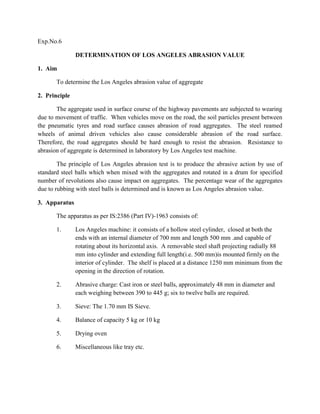
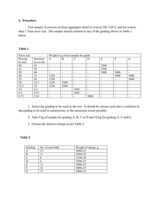

This document describes procedures for determining the Los Angeles abrasion value of aggregates. The test involves placing aggregate samples and steel balls into a rotating steel cylinder. The rotation causes the balls to abrade the aggregate particles. The percentage weight loss of the aggregates after a specified number of rotations is the Los Angeles abrasion value, which indicates the resistance of the aggregates to wear. The test is important because aggregates used in road surfaces need to withstand abrasion from vehicle traffic. The document provides details on the required apparatus, test samples, and step-by-step procedure.