1. CONCRTE MATERIALS LAB
Jollireddy Omprakash M-Tech, Assistant Professor, Department of CIVIL ENGINEERING, 9494509018. Page 1
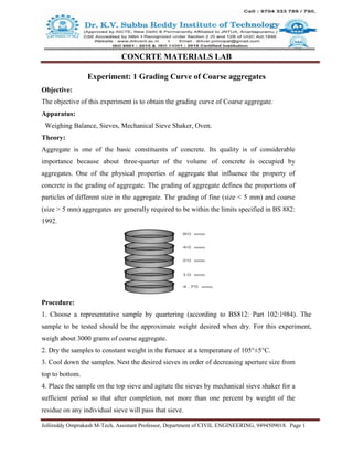
Experiment: 1 Grading Curve of Coarse aggregates
Objective:
The objective of this experiment is to obtain the grading curve of Coarse aggregate.
Apparatus:
Weighing Balance, Sieves, Mechanical Sieve Shaker, Oven.
Theory:
Aggregate is one of the basic constituents of concrete. Its quality is of considerable
importance because about three-quarter of the volume of concrete is occupied by
aggregates. One of the physical properties of aggregate that influence the property of
concrete is the grading of aggregate. The grading of aggregate defines the proportions of
particles of different size in the aggregate. The grading of fine (size < 5 mm) and coarse
(size > 5 mm) aggregates are generally required to be within the limits specified in BS 882:
1992.
Procedure:
1. Choose a representative sample by quartering (according to BS812: Part 102:1984). The
sample to be tested should be the approximate weight desired when dry. For this experiment,
weigh about 3000 grams of coarse aggregate.
2. Dry the samples to constant weight in the furnace at a temperature of 105°±5°C.
3. Cool down the samples. Nest the desired sieves in order of decreasing aperture size from
top to bottom.
4. Place the sample on the top sieve and agitate the sieves by mechanical sieve shaker for a
sufficient period so that after completion, not more than one percent by weight of the
residue on any individual sieve will pass that sieve.
2. CONCRTE MATERIALS LAB
Jollireddy Omprakash M-Tech, Assistant Professor, Department of CIVIL ENGINEERING, 9494509018. Page 2
5. Determine the weight of each size increment by weighing the residue contained on each
sieve. This may be done in a cumulative fashion by starting with the smallest particles in
the bottom pan. After this weight has been determine, add the next larger particles into the
same pan and determine the cumulative weight.
Tabular form & Calculation:
Coarse aggregate sample weight:__________________gms
Graph: Based on the results, draw the grading curve for each coarse aggregate together with
standard grading curve as given. Please give your comment on the properties of tested
aggregates.
Result: The grading curve of coarse aggregate is plotted.
BS Sieve
Size(mm)
Retained
Weight(gm)
Passed
weight(gm)
Retained
percentage%
Passed
percentage%
80
63
40
20
16
12.5
10
4.75
Pan
3. CONCRTE MATERIALS LAB
Jollireddy Omprakash M-Tech, Assistant Professor, Department of CIVIL ENGINEERING, 9494509018. Page 3
Experiment: 2 Grading Curve of Fine aggregates
Objective:
The objective of this experiment is to obtain the grading curve of Fine aggregates.
Apparatus:
Weighing Balance, Sieves, Mechanical Sieve Shaker, Oven.
Theory:
Aggregate is one of the basic constituents of concrete. Its quality is of considerable
importance because about three-quarter of the volume of concrete is occupied by
aggregates. One of the physical properties of aggregate that influence the property of
concrete is the grading of aggregate. The grading of aggregate defines the proportions of
particles of different size in the aggregate. The grading of fine (size < 5 mm) and coarse
(size > 5 mm) aggregates are generally required to be within the limits specified in BS 882:
1992.
Procedure:
1. Choose a representative sample by quartering (according to BS812: Part 102:1984). The
sample to be tested should be the approximate weight desired when dry. For this experiment,
weigh about 500 grams of fine aggregate.
2. Dry the samples to constant weight in the furnace at a temperature of 105°±5°C.
3. Cool down the samples. Nest the desired sieves in order of decreasing aperture size from
top to bottom.
4. CONCRTE MATERIALS LAB
Jollireddy Omprakash M-Tech, Assistant Professor, Department of CIVIL ENGINEERING, 9494509018. Page 4
4. Place the sample on the top sieve and agitate the sieves by mechanical sieve shaker for a
sufficient period so that after completion, not more than one percent by weight of the
residue on any individual sieve will pass that sieve.
5. Determine the weight of each size increment by weighing the residue contained on each
sieve. This may be done in a cumulative fashion by starting with the smallest particles in
the bottom pan. After this weight has been determine, add the next larger particles into the
same pan and determine the cumulative weight.
Tabular form & Calculation:
Fine aggregate sample weight:__________________gms
Graph: Based on the results, draw the grading curve for each Fine aggregate together with
standard grading curve as given. Please give your comment on the properties of tested
aggregates.
Result: The grading curve of Fine aggregate is plotted
BS Sieve
Size(mm)
Retained
Weight(gm)
Passed
weight(gm)
Retained
percentage%
Passed
percentage%
10
4.75
2.36
1.18
600 µm
300 µm
150 µm
5. CONCRTE MATERIALS LAB
Jollireddy Omprakash M-Tech, Assistant Professor, Department of CIVIL ENGINEERING, 9494509018. Page 5
Experiment: 3.1 Bulking of Fine aggregate
Objective:
To determine bulking of a given sample of fine aggregate.
Apparatus:
Measuring Cylinder, Container , Steel Rod (6mm Dia) & Sample sand
Theory:
When measuring sand by volume, allowance should be made for the fact that it can
occupy a greater volume when damp than when it is dry. This effect is known as BULKING.
The extent of bulking varies with the moisture content and the coarseness of the sand.
Procedure:
1. Take the sample sand and fill the measuring cylinder up to 200 ml
2. To make the necessary correction uses the steel rule but don’t compact the sand.
3. Transfer that sample to a container
4. Refill the measuring cylinder with 100ml water
5. Now refill the sand into measuring cylinder and stir it well with the help of steel rod.
6. CONCRTE MATERIALS LAB
Jollireddy Omprakash M-Tech, Assistant Professor, Department of CIVIL ENGINEERING, 9494509018. Page 6
6. Allow it to settle sometime.
7. The sand will be below the 200ml mark as shown in the below pic. Note this level as Y
Calculation:
S.No Description Sample No.
Sample 1 Sample 2 Sample 3
Volume of loose sand
Volume of saturated sand
A maximum bulk density of aggregate is obtained when the mixture contains 20-40% fine
aggregate by the total mass of the aggregate mix.
Result: Percentage bulking of sand sample is___________%
7. CONCRTE MATERIALS LAB
Jollireddy Omprakash M-Tech, Assistant Professor, Department of CIVIL ENGINEERING, 9494509018. Page 7
Experiment: 3.2 Bulking of Fine aggregate
Objective:
To ascertain the bulking phenomena of given sample of sand.
Apparatus:
Beaker, 1000ml measuring jar, mixing tray, Fine aggregate & water
Procedure:
1. Put sufficient quantity of dry sand into the beaker until it is about one-thirds full.
2. Level off the top of the sand and measure the height (H ) by pushing a steel rule vertically
down through the sand at the middle to the bottom. Measure weight of the sand.
3. Add 2% of water; mix it thoroughly in the container. Smooth and level the top surface
measure the height (H ) of soil. Find the height percentage increment.
4. Repeat the same procedure with increasing amount of water by 2% until percentage increment
of sand height is reduced and attends original level.
5. Plot a graph of percentage increment of sand height against percentage of water.
Observations:
Initial Height of sand in the Jar (H1 ):________ ml
Weight of fine aggregate: ____________gm
8. CONCRTE MATERIALS LAB
Jollireddy Omprakash M-Tech, Assistant Professor, Department of CIVIL ENGINEERING, 9494509018. Page 8
Results:
From the tabulated results and the plotted graph is is observed that, the given sand specimen
under goes maximum bulking at __________% of moisture contain.
Maximum percentage of bulking is______________
A maximum bulk density of aggregate is obtained when the mixture contains 20- 40% fine
aggregate by the total mass of the aggregate mix.
9. CONCRTE MATERIALS LAB
Jollireddy Omprakash M-Tech, Assistant Professor, Department of CIVIL ENGINEERING, 9494509018. Page 9
Experiment: 4 Specific Gravity of Coarse aggregate
Objective:
To determine the Specific gravity of coarse aggregate sample.
Apparatus:
Pycnometer, Thermostatically controlled oven to maintain temperature of 1000
to 1200
C & A
shallow tray.
Theory:
The specific gravity of an aggregate is considered to be a measure of strength or quality of the
material. Stones having low specific gravity are generally weaker than those with higher specific
gravity values. The specific gravity test helps in identification of stone.
Procedure:
1. A clean, dry pycnometer is taken and its empty weight is determined.
2. About 1000g of clean sample is taken into the pycnometer, and is weighed.
3. Water at 270
c is filled ,up in the pycnometer with aggregate sample to just immerse
sample.
4. Immediately after immersion the entrapped air is removed from the sample by shaking
pycnometer, placing a finger on the hole at the top of the sealed pycnometer.
5. Now the pycnometer is completely filled up with water till the hole at the top, and after
conforming that there is no more entrapped air in it, it is weighed.
6. The content of the pycnometer are discharged, and it is cleaned.
7. Water is filled up to the pycnometer, with out any entrapped air. It is then weighed.
For mineral filler, Specific gravity bottle is used and the material is filled upto one-third of
the capacity of bottle. The rest of the process of determining specific gravity is similar to the one
described for aggregates finer than 6.3mm.
10. CONCRTE MATERIALS LAB
Jollireddy Omprakash M-Tech, Assistant Professor, Department of CIVIL ENGINEERING, 9494509018. Page 10
Observations & Calculations:
Details Observed values
1. Weight of Pycnometer in air, w1g
2. Weight of aggregates & Pycnometer,w2g
3. Weight of aggregates & Pycnometer & Water, w3g
4. Weight of Pycnometer & Water W4g
5. Apparent Specific gravity=W2-w1/[(W2-w1)-(W3-W4)]
Result:
Specific gravity of tested sample of Coarse Aggregates is =
11. CONCRTE MATERIALS LAB
Jollireddy Omprakash M-Tech, Assistant Professor, Department of CIVIL ENGINEERING, 9494509018. Page 11
Experiment: 5 Specific Gravity of Fine aggregate
Objective:
To determine specific gravity of a given sample of fine aggregate.
Apparatus:
Pycnometer, Thermostatically controlled oven to maintain temperature of 1000
to 1200
C & A
shallow tray.
Theory:
The specific gravity of an aggregate is considered to be a measure of strength or quality of the
material. Stones having low specific gravity are generally weaker than those with higher specific
gravity values. The specific gravity test helps in identification of stone.
Procedure:
1. A clean, dry pycnometer is taken and its empty weight is determined.
2. About 1000g of clean sample is taken into the pycnometer, and is weighed.
3. Water at 270
c is filled ,up in the pycnometer with aggregate sample to just immerse
sample.
4. Immediately after immersion the entrapped air is removed from the sample by shaking
pycnometer, placing a finger on the hole at the top of the sealed pycnometer.
5. Now the pycnometer is completely filled up with water till the hole at the top, and after
conforming that there is no more entrapped air in it, it is weighed.
6. The content of the pycnometer are discharged, and it is cleaned.
7. Water is filled up to the pycnometer, with out any entrapped air. It is then weighed.
For mineral filler, Specific gravity bottle is used and the material is filled upto one-third of
the capacity of bottle. The rest of the process of determining specific gravity is similar to the one
described for aggregates finer than 6.3mm.
12. CONCRTE MATERIALS LAB
Jollireddy Omprakash M-Tech, Assistant Professor, Department of CIVIL ENGINEERING, 9494509018. Page 12
Observations & Calculations:
Details Observed values
1.Weight of Pycnometer in air, w1g
2.Weight of aggregates & Pycnometer,w2g
3. Weight of aggregates & Pycnometer & Water, w3g
4. Weight of Pycnometer & Water W4g
5.Apparent Specific gravity=W2-w1/[(W2-w1)-(W3-W4)]
Result:
Specific gravity of tested sample of Fine Aggregates is =
13. CONCRTE MATERIALS LAB
Jollireddy Omprakash M-Tech, Assistant Professor, Department of CIVIL ENGINEERING, 9494509018. Page 13
Experiment: 6 Specific Gravity of Cement
Objective:
To determine the specific gravity of cement using Le Chatelier Flask.
Apparatus:
(i) Le-Chatlier’s flask.
(ii) Weighing balance
(iii) Spoon
(iv) Stirrer
Theory:
In case of cement, specific gravity is determined by use of a Le Chatelier’s flask. In the
determination of specific gravity of cement, kerosene is used as a medium instead of water,
because water undergoes hydration reaction with cement, while kerosene does not react. The
specific gravity of OPC is generally around 3.15.
Procedure:
1. Clean and dry the specific gravity bottle and weight it with the stopper(W1).
2. Fill the specific gravity bottle with cement sample at least half of the bottle and weigh with
stopper (W2).
3. Fill the specific gravity bottle containing the cement, with kerosene (free of water) placing the
stopper and weigh it (W3).
4. While doing the above do not allow any air bubbles to remain in the specific gravity bottle.
5. After weighing the bottle, the bottle shall be cleaned and dried again.
6. Then fill it with fresh kerosene and weigh it with stopper(W4).
7. Remove the kerosene from the bottle and fill it with full of water and weigh it with stopper
(W5)
8. All the above weighing should be done at the room temperature of 270
C + 100
C
14. CONCRTE MATERIALS LAB
Jollireddy Omprakash M-Tech, Assistant Professor, Department of CIVIL ENGINEERING, 9494509018. Page 14
Observations & Calculations:
Details Observed values
1.Weight of empty bottle, W1g
2.Weight of bottle & Cement,W2g
3. Weight of bottle & Cement & Kerosene, W3g
4. Weight of Bottle & Full kerosene W4g
5. Weight of Bottle & Full Water W5g
6. Specific Gravity of Kerosene = W4-W1/(W5-W1)
5. Specific gravity of Cement =W2-W1/[(W4-W1)-(W3-W2)] ×SK
Result:
Specific gravity of tested sample Cement is =
15. CONCRTE MATERIALS LAB
Jollireddy Omprakash M-Tech, Assistant Professor, Department of CIVIL ENGINEERING, 9494509018. Page 15
Experiment: 7 Fineness of Cement
Objective:
To determine the Fineness of a given sample of cement by Sieving
Apparatus :
Test Sieve 90microns,
Weighing Balance,
Gauging Trowel& Brush,
Theory :
The fineness of cement has an important bearing on the rate of hydration and hence on the rate of gain of
strength and also on the rate of evolution of heat. Finer cement offers a greater surface area for hydration
and hence faster the development of strength. Increase in fineness of cement is also found to increase the
drying shrinkage of concrete.
Procedure :
1. Weigh accurately 100g of cement and place it on a standard 90 micron IS sieve.
2. Break down any air-set lumps in the cement sample with fingers.
3. Continuously sieve the sample giving circular and vertical motion for a period of 15 minutes.
4. Weigh the residue left on the sieve. As per IS code the percentage residue should not exceed
10%.
Observation & Calculation:
S.No Weight of sample taken (gms) Weight of residue (gms) Fineness %
Result:
The Fineness of given sample of Cement is------------%
16. CONCRTE MATERIALS LAB
Jollireddy Omprakash M-Tech, Assistant Professor, Department of CIVIL ENGINEERING, 9494509018. Page 16
Experiment: 8 Normal Consistency of Cement
Objective:
To determine the Normal Consistency of a given sample of cement.
Apparatus :
Vicat apparatus conforming to IS : 5513-1976, Balance, Gauging Trowel, Stop Watch, etc.
Theory:
Standard consistency is defined as the percentage water requirement of cement paste at which viscosity
of the paste becomes such that the plunger in a specially designed apparatus (known as Vicat’s
apparatus) penetrates a depth 5 to 7mm, measured from the bottom of the mould. Practical importance of
Standard consistency value is to determine amount of water needed to make paste for other tests of
cement.
Procedure:
(1) Prepare a paste of weighed quantity of cement (approx. 400 gms) with weighed quantity of
water (start from 20%-25%) taking care that mixing (gauging) remains between 3 to 5 minutes
and mixing shall be completed before any signs of setting becomes visible.
(2) Fill the Vicat mould with the paste, mould should rest on non porous base.
(3) Place the mould under Vicat’s apparatus. The plunger attached to a movable rod is gently
lowered on the paste.
(4) Settlement of plunger is noted, penetration from bottom is equal to the difference of mould
height and settlement of plunger. If penetration of the plunger is within 5-7 mm from bottom,
then water added is correct. Otherwise, water is added and process is repeated.
Observation:
S.No Weight of cement
(gm)
Percentage of
water (%)
Weight of water
(gm)
Plunger penetration
(mm)
17. CONCRTE MATERIALS LAB
Jollireddy Omprakash M-Tech, Assistant Professor, Department of CIVIL ENGINEERING, 9494509018. Page 17
Result:
The normal consistency of a given sample of cement is _ _ _ _ %
18. CONCRTE MATERIALS LAB
Jollireddy Omprakash M-Tech, Assistant Professor, Department of CIVIL ENGINEERING, 9494509018. Page 18
Experiment: 9 Initial and Final setting times of Cement
Objective:
To determine the initial and final setting time of a given sample of cement.
Apparatus :
Vicat apparatus conforming to IS : 5513-1976, Balance, Gauging Trowel, Stop Watch, etc.
Theory:
For convenience, initial setting time is regarded as the time elapsed between the moments that
the water is added to the cement, to the time that the paste starts losing its plasticity. The final
setting time is the time elapsed between the moment the water is added to the cement, and the
time when the paste has completely lost its plasticity and has attained sufficient firmness to resist
certain definite pressure.
Procedure:
Prepare a neat 300 gms cement paste by gauging the cement with 0.85 times the water required
to give a paste of standard consistency. Potable or distilled water shall be used in preparing the
paste.
2. Start a stop-watch at the instant when water is added to the cement. Fill the Vicat mould with a
cement paste gauged as above, the mould resting on a nonporous plate. Fill the mould
completely and smooth off the surface of the paste making it level with the top of the mould.
3. Immediately after moulding, place the test block in the moist closet or moist room and allow it
to remain there except when determinations of time of setting are being made.
4.Determination of Initial Setting Time: Place the test block confined in the mould and resting
on the non-porous plate, under the rod bearing the needle ( C ); lower the needle gently until it
comes in contact with the surface of the test block and quickly release, allowing it to penetrate
into the test block
5. Repeat this procedure until the needle, when brought in contact with the test block and
released as described above, fails to pierce the block beyond 5.0 ± 0.5 mm measured from the
bottom of the mould shall be the initial setting time.
19. CONCRTE MATERIALS LAB
Jollireddy Omprakash M-Tech, Assistant Professor, Department of CIVIL ENGINEERING, 9494509018. Page 19
6. Determination of Final Setting Time: Replace the needle (C) of the Vicat apparatus by the
needle with an annular attachment (F).
7. The cement shall be considered as finally set when, upon applying the needle gently to the
surface of the test block, the needle makes an impression thereon, while the attachment fails to
do so.
8. The period elapsing between the time when water is added to the cement and the time at which
the needle makes an impression on the surface of test block while the attachment fails to do so
shall be the final setting time.
Observation:
1. Weight of given sample of cement is _ _ _ _ gms
2. The normal consistency of a given sample of cement is _ _ _ _ %
3. Volume of water addend (0.85 times the water required to give a paste of standard consistency)
for preparation of test block _ _ _ _ ml
S.No Setting time (seconds) Penetration (mm) Remarks
Figure:
Result:
i) The initial setting time of the cement sample is found to be------------------
ii) The final setting time of the cement sample is found to be ------------------
20. CONCRTE MATERIALS LAB
Jollireddy Omprakash M-Tech, Assistant Professor, Department of CIVIL ENGINEERING, 9494509018. Page 20
Experiment: 10 Soundness test of Cement
Objective:
To determine the soundness of a given sample of cement by Le-Chatelier method.
Apparatus :
Le- Chatelier test apparatus conform to IS : 5514-1969, Balance, Gauging Trowel, Water Bath
etc.
Theory:
It is very important that the cement after setting shall not undergo any appreciable change of
volume. Certain cements have been found to undergo a large expansion after setting causing
disruption of the set and hardened mass. This will cause serious difficulties for the durability of
structures when such cement is used. The unsoundness in cement is due to the presence of excess
of lime than that could be combined with acidic oxide at the kiln. It is also likely that too high a
proportion of magnesium content or calcium sulphate content may cause unsoundness in cement.
Soundness of cement may be determined by two methods, namely Le-Chatelier method and
autoclave method
Procedure:
1. Place the lightly oiled mould on a lightly oiled glass sheet and fill it with cement paste formed
by gauging cement with 0.78 times the water required to give a paste of standard consistency
2. The paste shall be gauged in the manner and under the conditions prescribed, taking care to
keep the edges of the mould gently together while this operation is being performed.
3. Cover the mould with another piece of lightly oiled glass sheet, place a small weight on this
covering glass sheet and immediately submerge the whole assembly in water at a temperature of
27 ± 2°C and keep there for 24 hours.
4. Measure the distance separating the indicator points to the nearest 0.5 mm. Submerge the
mould again in water at the temperature prescribed above.
5. Bring the water to boiling, with the mould kept submerged, in 25 to 30 minutes, and keep it
boiling for three hours. Remove the mould from the water, allow it to cool and measure the
distance between the indicator points.
21. CONCRTE MATERIALS LAB
Jollireddy Omprakash M-Tech, Assistant Professor, Department of CIVIL ENGINEERING, 9494509018. Page 21
6. The difference between these two measurements indicates the expansion of the cement. This
must not exceed 10 mm for ordinary, rapid hardening and low heat Portland cements. If in case
the expansion is more than 10 mm as tested above, the cement is said to be unsound.
Observation:
S.No Distance separating
the indicator
submerge in normal
temp water for 24
hours
Distances separating
the indicator
submerge in boiling
for three hours.
The difference
between these two
measurements
Remarks
Result:
The given cement is said to be sound / unsound
22. CONCRTE MATERIALS LAB
Jollireddy Omprakash M-Tech, Assistant Professor, Department of CIVIL ENGINEERING, 9494509018. Page 22
Experiment: 11 Compressive strength test of Cement
Objective:
To determining the compressive strength of cement from tests on mortar cubes compacted by
means of standard vibration machine.
Apparatus :
Tray.TrowelCube mould of size 70.60mm, Platform vibrator (or) Equipment for hand
compaction, Compression testing machine, Balance to measure weight
Theory:
The compressive strength of hardened cement is the most important of all the properties.
Therefore, it is not surprising that the cement is always tested for its strength at the laboratory
before the cement is used in important works. Strength tests are not made on neat cement paste
because of difficulties of excessive shrinkage and subsequent cracking of neat cement.
Procedure:
1. Preparation of test specimens - Clean appliances shall be used for mixing and the temperature
of water and that of the test room at the time when the above operations are being performed
shall be 27 ± 2°C. Potable/distilled water shall be used in preparing the cubes.
2. The material for each cube shall be mixed separately and the quantity of cement, standard sand
and water shall be as follows:
Cement 200 g and Standard Sand 600 g
Water (P/4 + 0.3) percent of combined mass of cement and sand, where P is the percentage of
water required to produce a paste of standard consistency determined as described in IS : 4031
(Part 4)-1988 or Experiment No.1(a).
3. Place on a nonporous plate, a mixture of cement and standard sand. Mix it dry with a trowel
for one minute and then with water until the mixture is of uniform colour. The quantity of water
to be used shall be as specified in step 2. The time of mixing shall in any event be not less than 3
min and should the time taken to obtain a uniform colour exceed 4 min, the mixture shall be
rejected and the operation repeated with a fresh quantity of cement, sand and water.
23. CONCRTE MATERIALS LAB
Jollireddy Omprakash M-Tech, Assistant Professor, Department of CIVIL ENGINEERING, 9494509018. Page 23
4. Moulding Specimens - In assembling the moulds ready for use, treat the interior faces of the
mould with a thin coating of mould oil.
5. Place the assembled mould on the table of the vibration machine and hold it firmly in position
by means of a suitable clamp. Attach a hopper of suitable size and shape securely at the top of
the mould to facilitate filling and this hopper shall not be removed until the completion of the
vibration period.
6. Immediately after mixing the mortar in accordance with step 1 & 2, place the mortar in the
cube mould and prod with the rod. Place the mortar in the hopper of the cube mould and prod
again as specified for the first layer and then compact the mortar by vibration.
7. The period of vibration shall be two minutes at the specified speed of 12 000 ± 400 vibration
per minute.
8. At the end of vibration, remove the mould together with the base plate from the machine and
finish the top surface of the cube in the mould by smoothing the surface with the blade of a
trowel.
9. Curing Specimens - keep the filled moulds in moist closet or moist room for 24 ± 1 hour after
completion of vibration. At the end of that period, remove them from the moulds and
immediately submerge in clean fresh water and keep there until taken out just prior to breaking.
10. The water in which the cubes are submerged shall be renewed every 7 days and shall be
maintained at a temperature of 27 ± 2°C. After they have been taken out and until they are
broken, the cubes shall not be allowed to become dry.
11. Test three cubes for compressive strength for each period of curing mentioned under the
relevant specifications (i.e. 3 days, 7 days, 28 days)
12. The cubes shall be tested on their sides without any packing between the cube and the steel
plattens of the testing machine. One of the plattens shall be carried on a base and shall be self-
adjusting, and the load shall be steadily and uniformly applied, starting from zero at a rate of 35
N/mm2/min.
24. CONCRTE MATERIALS LAB
Jollireddy Omprakash M-Tech, Assistant Professor, Department of CIVIL ENGINEERING, 9494509018. Page 24
Observation:
Calculation :
The measured compressive strength of the cubes shall be calculated by dividing the maximum load
applied to the cubes during the test by the cross-sectional area, calculated from the mean dimensions of
the section and shall be expressed to the nearest 0.5 N/mm2. In determining the compressive strength,
do not consider specimens that are manifestly faulty, or that give strengths differing by more than 10
percent from the average value of all the test specimens.
Result:
i) The average 7 Days Compressive Strength of given cement sample is found to be …..…..
ii) The average 28 Days Compressive Strength of given cement sample is found to be …..…..
25. CONCRTE MATERIALS LAB
Jollireddy Omprakash M-Tech, Assistant Professor, Department of CIVIL ENGINEERING, 9494509018. Page 25
Experiment: 12 Slump, Compaction factor and Vee-Bee time tests on concrete
Objective:
I. To determine the relative consistency of freshly mixed concrete by the use of Slump Test.
II. To determine the relative consistency of freshly mixed concrete by the use of
Compacting Factor Test
III. The determination of consistency of concrete using a Vee-Bee Consistometer, which
determines the time required for transforming, by vibration, a concrete specimen in the
shape of a conical frustum into a cylinder.
Apparatus :
I. The Slump Cone apparatus for conducting the slump test essentially consists of a metallic
mould in the form of a frustum of a cone having the internal dimensions as under: Bottom
diameter : 20 cm, Top diameter : 10 cm, Height : 30 cm and the thickness of the metallic
sheet for the mould should not be thinner than 1.6 mm
Weights and weighing device, Tamper ( 16 mm in diameter and 600 mm length), Ruler,
Tools and containers for mixing, or concrete mixer etc.
II. Compacting Factor Apparatus: Trowel, Scoop about 150 mm long., Balance capable of
weighing up to 25 kg with the sensibility of 10 g. Weights and weighing device, Tamper (
16 mm in diameter and 600 mm length), Ruler, Tools and containers for mixing, or
concrete mixer etc.
III. Vee Bee Consistometer : a) A vibrator table resting upon elastic supports, b) A metal pot,
c) A sheet metal cone, open at both ends, and d) A standard iron rod. Weights and
weighing device, Tamper ( 16 mm in diameter and 600 mm length), Ruler, Tools and
containers for mixing, or concrete mixer etc.
Theory:
Slump Test: Slump test is the most commonly used method of measuring consistency of
concrete which can be employed either in laboratory or at site of work. It is not a suitable method
for very wet or very dry concrete. It does not measure all factors contributing to workability, nor
is it always representative of the placability of the concrete.
26. CONCRTE MATERIALS LAB
Jollireddy Omprakash M-Tech, Assistant Professor, Department of CIVIL ENGINEERING, 9494509018. Page 26
The pattern of slump is shown in Fig. It indicates the characteristic of concrete in addition to the
slump value. If the concrete slumps evenly it is called true slump. If one half of the cone slides
down, it is called shear slump. In case of a shear slump, the slump value is measured as the
difference in height between the height of the mould and the average value of the subsidence.
Compacting Factor Test: The compacting factor test is designed primarily for use in the
laboratory but it can also be used in the field. It is more precise and sensitive than the slump test
and is particularly useful for concrete mixes of very low workability as are normally used when
concrete is to be compacted by vibration. The method applies to plain and air-entrained concrete,
made with lightweight, normal weight or heavy aggregates having a nominal maximum size of
40 mm or less but not to aerated concrete or no-fines concrete.
Vee-Bee Consistometer: This test is more appropriate for stiff concrete mixes having low and
very low workability. The slump value of such mixes cannot be determined by slump cone test.
Therefore, this test is advantageous as compared to slump or compaction factor test in the sense
that in this test the treatment given to concrete is very close to the actual treatment provided in
the field.
Procedure:
I. Slump Test:
(1) Take Mix proportion: 1: 1.5:3 by weight; Use three different W/C ratio=-0.4, 0.5, 0.6 to
prepare three mixes.
(2) Clean the internal surface of the mould thoroughly and it should be freed from superfluous
moisture.
(3) Place the mould on a smooth, horizontal, rigid and non-absorbent surface, such as a
carefully leveled metal plate, and fixed it.
(4) Fill the mould with freshly prepared concrete in four layers and compact each layer by
temping with twenty five stokes of temping rod. After the top layer has been rodded, struck
off the excess concrete, make level with a trowel or tamping rod.
(5) Carefully lift the mould vertically upwards, so as not to disturb the concrete cone.
(6) Determine the level difference between the height of the mould and the highest point of the
subsided concrete.
27. CONCRTE MATERIALS LAB
Jollireddy Omprakash M-Tech, Assistant Professor, Department of CIVIL ENGINEERING, 9494509018. Page 27
(7) Height difference in mm is taken as Slump of concrete & Tabulate slump value for each test.
Compaction factor Test
(1) Prepare mix & Clean the inner surface of the upper, lower hopper and cylindrical mould of
the compaction factor apparatus.
(2) Note down the dimensions of upper, lower hopper and cylindrical mould and record the
dimension with a neat sketch of the apparatus in your report.
(3) Take the weight of the cylinder, say W1
(4) Place the concrete mix in the upper hopper up to the brim.
(5) Open trap door of upper hopper to allow concrete to fall in the lower hopper.
(6) Next open trap door of lower hopper to allow concrete to fall in to the cylindrical mould.
(7) For a dry mix, a slight poking by a rod may be required to set the concrete in motion.
(8) The concrete is made leveled at the top of the cylinder. Take the weight of cylinder and
partially compacted concrete, say W2
(9)The cylinder is emptied and then re-filled with the same sample of concrete in layers
approximately 50 mm deep.
(10)Each layer is heavily rammed (preferably vibrated) so as to obtain full compaction.
(11) Top surface is then carefully made leveled with the top of the cylinder .
(12) Take weight of the fully compacted concrete with the mould, say W3. Calculate compaction
factor.
Vee-Bee Test:
1) Place the slump cone in the cylinder of the vee-bee apparatus. Fill it with fresh concrete in the
standard manner as described for the slump test.
2) Remove the cone and place the transparent disc of the apparatus on the top of the
concrete cone gently touching it. The disc has a standard weight on it.
3) Switch on the vibrating table and start the stop watch simultaneously to measure the time
required for the conical shape to become cylindrical as seen through the transparent plant. As
soon as the slurry covers the disc uniformly, stop the watch.
Observation:
Slump Test
28. CONCRTE MATERIALS LAB
Jollireddy Omprakash M-Tech, Assistant Professor, Department of CIVIL ENGINEERING, 9494509018. Page 28
S.No W/C ratio Height of mould
H1
(mm)
Height of
Subsided concrete
H2 (mm)
Slump
H1-H2
(mm)
Compaction factor Test
S.No Descrption Sample
1. Weight of Empty Cylinder (W1)
2. Weight of Cylinder + Free Fall Concrete (W2)
3. Weight of Cylinder + Hand Compacted Concrete (W2)
4. Weight of Partially Compacted Concrete (Wp=W2-W1)
5. Weight of Fully Compacted Concrete (Wf=W2-W1)
6 The Compacting Factor =Wp/Wf
29. CONCRTE MATERIALS LAB
Jollireddy Omprakash M-Tech, Assistant Professor, Department of CIVIL ENGINEERING, 9494509018. Page 29
Vee-Bee Test:
The time required for the shape of concrete to change from slump cone shape to cylindrical
shape in seconds is known as Vee Bee Degree.
Vee-Bee time=
30. CONCRTE MATERIALS LAB
Jollireddy Omprakash M-Tech, Assistant Professor, Department of CIVIL ENGINEERING, 9494509018. Page 30
Result:
1. The slump of concrete ……….. mm indicate Low/ Medium/ High Degree of workability
2. The compaction factor of concrete -----------
3. The Vee Bee Degre of concrete ……….. sec indicate Low/ Medium/ High Degree of
workability
31. CONCRTE MATERIALS LAB
Jollireddy Omprakash M-Tech, Assistant Professor, Department of CIVIL ENGINEERING, 9494509018. Page 31
Experiment: 13 Compressive strength of Concrete
Objective:
To determine compressive strength of concrete cubes
Apparatus:
Concrete cube 150 mm x 150 mm x 150 mm size, Curing tank, Compressive testing machine,
weighing device & Tamping rod.
Theory:
Concrete is very strong in compression and for structural design purpose, one has to know the
compressive strength by testing hardened concrete specimen. In India, cube specimen 150 mm
size is taken as standard. However, standard cylinder (300 mm height, 150 mm dia) is also
usedin many countries. Tests shall be made at recognized ages of the test specimens, the most
usual being 7 and 28 days. Where it may be necessary to obtain the early strengths, tests may be
made at the ages of 24 hours ± ½ hour and 72 hours ± 2 hours. The ages shall be calculated from
the time of the addition of water to the dry ingredients.
Number of Specimens - At least three specimens, preferably from different batches, shall be
made for testing at each selected age.
Procedure:
1. Sampling of Materials - Samples of aggregates for each batch of concrete shall be of the
desired grading and shall be in an air-dried condition. The cement samples, on arrival at the
laboratory, shall be thoroughly mixed dry either by hand or in a suitable mixer in such a manner
as to ensure the greatest possible blending and uniformity in the material.
2. Proportioning - The proportions of the materials, including water, in concrete mixes used for
determining the suitability of the materials available, shall be similar in all respects to those to be
employed in the work.
3. Weighing - The quantities of cement, each size of aggregate, and water for each batch shall be
determined by weight, to an accuracy of 0.1 percent of the total weight of the batch.
4. Mixing Concrete - The concrete shall be mixed by hand, or preferably, in a laboratory batch
mixer, in such a manner as to avoid loss of water or other materials. Each batch of concrete shall
32. CONCRTE MATERIALS LAB
Jollireddy Omprakash M-Tech, Assistant Professor, Department of CIVIL ENGINEERING, 9494509018. Page 32
be of such a size as to leave about 10 percent excess after moulding the desired number of test
specimens.
5. Mould - Test specimens cubical in shape shall be 15 × 15 × 15 cm. If the largest nominal size
of the aggregate does not exceed 2 cm, 10 cm cubes may be used as an alternative. Cylindrical
test specimens shall have a length equal to twice the diameter.
6. Compacting - The test specimens shall be made as soon as practicable after mixing, and in
such a way as to produce full compaction of the concrete with neither segregation nor excessive
laitance.
7. Curing - Keep the cubes/ cylinders in laboratory for 24 hours. After 24 hours, dismantle the
plates of cube mould and split up the parts of cylindrical mould to remove specimens of
hardened concrete carefully without any damage. The test specimens shall be stored in a place,
free from vibration, in moist air of at least 90 percent relative humidity and at a temperature of
27° ± 2°C for 24 hours ± ½ hour from the time of addition of water to the dry ingredients.
8. Placing the Specimen in the Testing Machine - The bearing surfaces of the testing machine
shall be wiped clean and any loose sand or other material removed from the surfaces of the
specimen which are to be in contact with the compression platens.
9. In the case of cubes, the specimen shall be placed in the machine in such a manner that the
load shall be applied to opposite sides of the cubes as cast, that is, not to the top and bottom.
10. The axis of the specimen shall be carefully aligned with the centre of thrust of the spherically
seated platen. No packing shall be used between the faces of the test specimen and the steel
platen of the testing machine.
11. The load shall be applied without shock and increased continuously at a rate of
approximately 140 kg/sq cm/min until the resistance of the specimen to the increasing load
breaks down and no greater load can be sustained.
12. The maximum load applied to the specimen shall then be recorded and the appearance of the
concrete and any unusual features in the type of failure shall be noted.
33. CONCRTE MATERIALS LAB
Jollireddy Omprakash M-Tech, Assistant Professor, Department of CIVIL ENGINEERING, 9494509018. Page 33
Observations:
Calculations:
Compressive strength of concrete = Load/Area
Result:
i) The average 7 Days Compressive Strength of concrete sample is found to be …..…..
ii) The average 28 Days Compressive Strength of concrete sample is found to be …..…..
34. CONCRTE MATERIALS LAB
Jollireddy Omprakash M-Tech, Assistant Professor, Department of CIVIL ENGINEERING, 9494509018. Page 34
Experiment: 14 Split tensile strength of Concrete
Objective:
To determine the splitting tensile strength of cylindrical concrete specimens.
Apparatus:
Concrete cylinders 150 mm x 300 mm size, Curing tank, Compressive testing machine, weighing
device & tamping rod.
Theory:
Tests shall be made at recognized ages of the test specimens, the most usual being 7 and 28 days.
Where it may be necessary to obtain the early strengths, tests may be made at the ages of 24
hours ± ½ hour and 72 hours ± 2 hours. The ages shall be calculated from the time of the
addition of water to the dry ingredients. At least three specimens, preferably from different
batches, shall be made for testing at each selected age.
Procedure:
1. Sampling of Materials - Samples of aggregates for each batch of concrete shall be of the desired
grading and shall be in an air-dried condition. The cement samples, on arrival at the laboratory, shall
be thoroughly mixed dry either by hand or in a suitable mixer in such a manner as to ensure the
greatest possible blending and uniformity in the material.
2. Proportioning - The proportions of the materials, including water, in concrete mixes used for
determining the suitability of the materials available, shall be similar in all respects to those to be
employed in the work.
3. Weighing - The quantities of cement, each size of aggregate, and water for each batch shall be
determined by weight, to an accuracy of 0.1 percent of the total weight of the batch.
4. Mixing Concrete - The concrete shall be mixed by hand, or preferably, in a laboratory batch mixer,
in such a manner as to avoid loss of water or other materials. Each batch of concrete shall be of such a
size as to leave about 10 percent excess after moulding the desired number of test specimens.
5. Mould - The cylindrical mould shall be of 150 mm diameter and 300 mm height conforming to IS:
35. CONCRTE MATERIALS LAB
Jollireddy Omprakash M-Tech, Assistant Professor, Department of CIVIL ENGINEERING, 9494509018. Page 35
10086-1982.
6. Compacting - The test specimens shall be made as soon as practicable after mixing, and in such a
way as to produce full compaction of the concrete with neither segregation nor excessive laitance.
7. Curing - Keep the cylinders in laboratory for 24 hours. After 24 hours, dismantle the plates of
cylinder mould and split up the parts of cylindrical mould to remove specimens of hardened concrete
carefully without any damage. The test specimens shall be stored in a place, free from vibration, in
moist air of at least 90 percent relative humidity and at a temperature of 27° ± 2°C for 24 hours ± ½
hour from the time of addition of water to the dry ingredients.
8. Placing the Specimen in the Testing Machine - The bearing surfaces of the supporting and
loading rollers shall be wiped clean, and any loose sand or other material removed from the surfaces of
the specimen where they are to make contact with the rollers.
9. Two bearings strips of nominal (1/8 in i.e 3.175mm) thick plywood, free of imperfections,
approximately (25mm) wide, and of length equal to or slightly longer than that of the specimen should
be provided for each specimen.
10. The bearing strips are placed between the specimen and both upper and lower bearing blocks of the
testing machine or between the specimen and the supplemental bars or plates.
11. Draw diametric lines an each end of the specimen using a suitable device that will ensure that they
are in the same axial plane. Center one of the plywood strips along the center of the lower bearing
block.
12. Place the specimen on the plywood strip and align so that the lines marked on the ends of the
specimen are vertical and centered over the plywood strip.
13. Place a second plywood strip lengthwise on the cylinder, centered on the lines marked on the ends
of the cylinder. Apply the load continuously and without shock, at a constant rate within, the range of
689 to 1380 kPa/min splitting tensile stress until failure of the specimen
14. Record the maximum applied load indicated by the testing machine at failure. Note the typeof
failure and appearance of fracture.
36. CONCRTE MATERIALS LAB
Jollireddy Omprakash M-Tech, Assistant Professor, Department of CIVIL ENGINEERING, 9494509018. Page 36
Observations:
Calculations:
Calculate the splitting tensile strength of the specimen as follows:
𝑻 =
𝟐𝑷
𝝅𝑳𝒅
Where;
T = Splitting tensile strength
P = Maximum applied load indicated by testing machine
L = Length, m
d = diameter
Result:
i) The average 7 Days Tensile Strength of concrete sample is found to be …..…..
ii) The average 28 Days Tensile Strength of concrete sample is found to be …..…..
37. CONCRTE MATERIALS LAB
Jollireddy Omprakash M-Tech, Assistant Professor, Department of CIVIL ENGINEERING, 9494509018. Page 37
Experiment: 15 Non destructive test on Concrete (Rebound Hammer)
Objective:
To know the compressive strength of the concrete by relating the rebound index and the
compressive strength.
Apparatus:
Rebound hammer
Principle:
When the plunger of rebound hammer is pressed against the surface of the concrete, the spring
controlled mass rebounds and the extent of such rebound depends upon the surface hardness of
concrete. The surface hardness and therefore the rebound is taken to be related to the
compressive strength of the concrete. The rebound is read off along a graduated scale and is
designated as the rebound number or rebound index.
Procedure:
1. For testing, smooth, clean and dry surface is to be selected. If loosely adhering scale is present, this
should be rubbed of with a grinding wheel or stone. Rough surfaces resulting from incomplete
compaction, loss of grout, spalled or tooled surfaces do not give reliable results and should be avoided.
2. The point of impact should be at least 20 mm away from any edge or shape discontinuity.
3. For taking a measurement, the rebound hammer should be held at right angles to the surface of the
concrete member. The test can thus be conducted horizontally on vertical surfaces or vertically
upwards or downwards on horizontal surfaces. If the situation demands, the rebound hammer can be
held at intermediate angles also, but in each case, the rebound number will be different for the same
concrete.
4. Rebound hammer test is conducted around all the points of observation on all accessible faces of
the structural element. Concrete surfaces are thoroughly cleaned before taking any measurement.
Around each point of observation, six readings of rebound indices are taken and average of these
readings after deleting outliers as per IS:8900-1978 becomes the rebound index for the point of
observation
38. CONCRTE MATERIALS LAB
Jollireddy Omprakash M-Tech, Assistant Professor, Department of CIVIL ENGINEERING, 9494509018. Page 38
Observations & Calculations:
A Rebound hammer test graph is prepared after obtaining the correlation between compressive
strength and rebound number (rebound index), the strength of the structure can be assessed.
In general, the rebound number increases as the strength increases and is also affected by a
number of parameters i.e. types of cement, types of aggregate, surface condition of the
concrete, and moisture content of the concrete, curing, and age of concrete, carbonation of
concrete surface, etc.
Moreover, the rebound index is indicative of the compressive strength of concrete up to limited
depth from the surface. The internal cracks, flaws, etc., or heterogeneity among the cross–
section will not be indicated by rebound numbers. rebound hammer test values should be taken
into account.
Average Rebound Number Quality of Concrete
> 40 Very Good Hard Layer
30 to 40 Good Layer
20 to 30 Fair
< 20 Poor Concrete
0 Delaminated
Result:
The average compressive strength of concrete is ----------------------