Downloaded 1,013 times
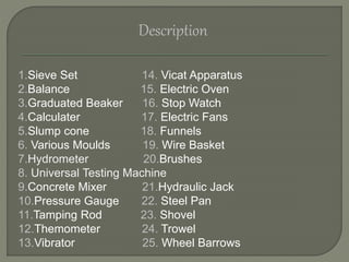
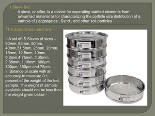
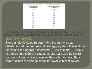
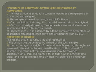
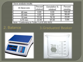
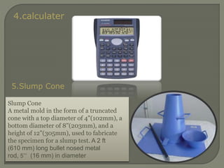
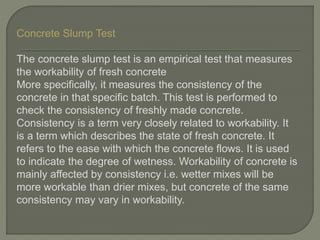
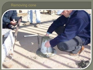
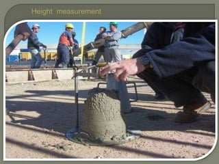
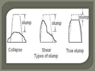
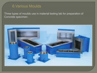
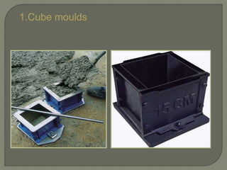
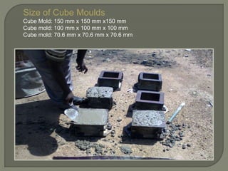
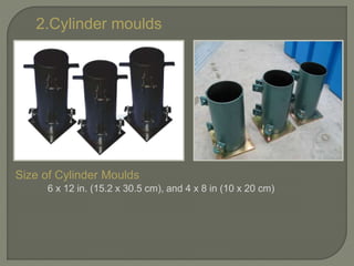
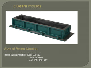
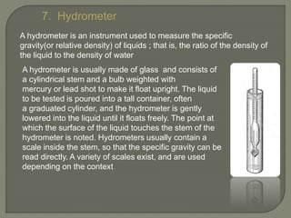
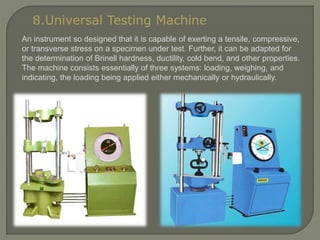
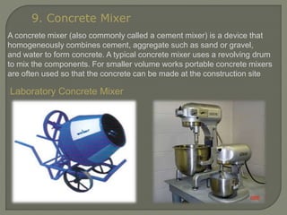
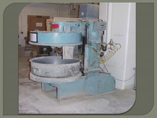
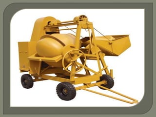
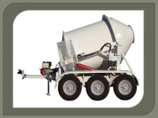
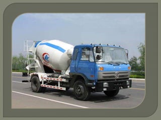
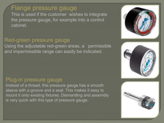
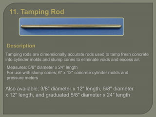
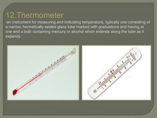
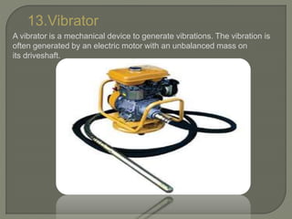
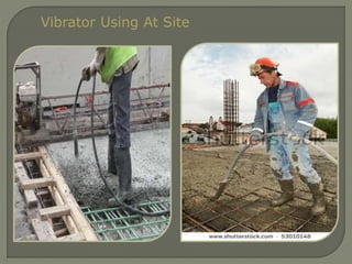
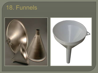

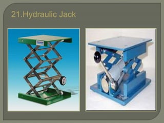
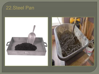
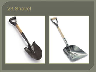


This document lists and describes various types of equipment used in a material testing lab. It includes sieves of different sizes for sieve analysis to determine particle size distribution of aggregates. It also describes a slump cone and procedure for concrete slump testing to measure workability. Other equipment described includes a balance, graduated beaker, calculator, molds, hydrometer, universal testing machine, concrete mixer, pressure gauge, tamping rod, thermometer, internal and external vibrators.


![Geotechnical Engineering-I [Lec #11: USCS & AASHTO]](https://cdn.slidesharecdn.com/ss_thumbnails/11-180923183816-thumbnail.jpg?width=640&height=640&fit=bounds)


