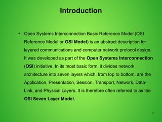
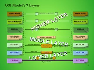
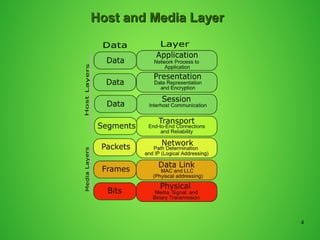
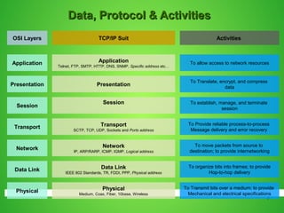
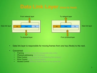
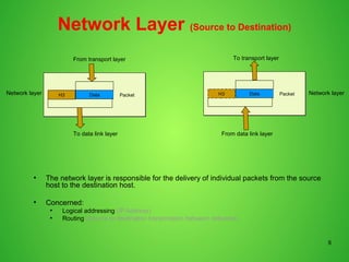
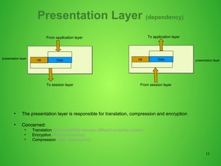
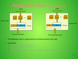
1
OSI MODEL
Rahul Bandhe
2
Introduction
●
Open Systems Interconnection Basic Reference Model (OSI
Reference Model or OSI Model) is an abstract description for
layered communications and computer network protocol design.
It was developed as part of the Open Systems Interconnection
(OSI) initiative. In its most basic form, it divides network
architecture into seven layers which, from top to bottom, are the
Application, Presentation, Session, Transport, Network, Data-
Link, and Physical Layers. It is therefore often referred to as the
OSI Seven Layer Model.
3
APPLICATION
APPLICATION
PRESENTATION
PRESENTATION
SESSION
SESSION
TRANSPORT
TRANSPORT
NETWORK
NETWORK
DATA LINK
DATA LINK
PHYSICAL
PHYSICAL
APPLICATION
APPLICATION
PRESENTATION
PRESENTATION
SESSION
SESSION
TRANSPORT
TRANSPORT
NETWORK
NETWORK
DATA LINK
DATA LINK
PHYSICAL
PHYSICAL
MIDDLE LAYER
MIDDLE LAYER
HIGHER LAYER
HIGHER LAYER
Application to Application
Process to Process
LOWER LAYER
LOWER LAYER
Hop to Hop
Switch
Hop to Hop
Physical Medium
Hub and Repeater
Router
Source to Destination
OSI Model's 7 LayersOSI Model's 7 Layers
4
Host and Media LayerHost and Media Layer
5
TCP/IP SuitOSI Layers
Application
Telnet, FTP, SMTP, HTTP, DNS, SNMP, Specific address etc…
Session
Presentation
Transport
SCTP, TCP, UDP, Sockets and Ports address
Network
IP, ARP/RARP, ICMP, IGMP, Logical address
Data Link
IEEE 802 Standards, TR, FDDI, PPP, Physical address
Application
Session
Presentation
Transport
Network
Data Link
Activities
To allow access to network resources
To establish, manage, and terminate
session
To Translate, encrypt, and compress
data
To Provide reliable process-to-process
Message delivery and error recovery
To move packets from source to
destination; to provide internetworking
To organize bits into frames; to provide
Hop-to-hop delivery
Data, Protocol & ActivitiesData, Protocol & Activities
Physical
Medium, Coax, Fiber, 10base, Wireless
Physical
To Transmit bits over a medium; to provide
Mechanical and electrical specifications
6
Physical Layer
●
One of the major function of the physical layer is to move data in the form of electromagnetic signals
across a transmission medium.
●
Its responsible for movements of individual bits from one hop (Node) to next.
●
Both data and the signals can be either analog or digital.
●
Transmission media work by conducting energy along a physical path which can be wired or wireless
●
Concerned:
●
Physical characteristics of interface and medium (Transmission medium)
●
Representation of bits (stream of bits (0s or 1s) with no interpretation and encoded into signals)
●
Data rate (duration of a bit, which is how long it last)
●
Synchronization of bits (sender and receivers clock must be synchronized)
●
Line configuration (Point-to-Point, Point-to-Multipoint)
●
Physical topology
●
Transmission mode (Simplex, half duplex, full duplex)
10101000000010111110
From data link layer
10101000000010111110
To data link layer
Physical layer
Physical layer
Transmission medium
7
Data Link Layer (Host to Host)
●
Data link layer is responsible for moving frames from one hop (Node) to the next.
●
Concerned:
●
Framing (stream of bits into manageable data units)
●
Physical addressing (MAC Address)
●
Flow Control (mechanism for overwhelming the receiver)
●
Error Control (trailer, retransmission)
●
Access Control (defining master device in the same link)
DataH2 T2
From network layer
DataH2 T2
To network layer
To physical layer From physical layer
Data link layer Data link layer
8
Network Layer (Source to Destination)
●
The network layer is responsible for the delivery of individual packets from the source
host to the destination host.
●
Concerned:
●
Logical addressing (IP Address)
●
Routing (Source to destination transmission between networks)
DataH3 Packet
From transport layer
To data link layer
DataH3 Packet
To transport layer
From data link layer
Network layer Network layer
9
Transport Layer (Process to Process)
●
The transport layer is responsible for the delivery of a message from one process to
another
●
Concerned:
●
Service-point addressing (Port address)
●
Segmentation and reassembly (Sequence number)
●
Connection control (Connectionless or connection oriented)
●
Flow control (end to end)
●
Error Control (Process to Process)
SegmentsSegments
DataH4
From session layer
To network layer
Transport layer DataH4 DataH4
SegmentsSegments
DataH4
From session layer
From network layer
Transport layerDataH4 DataH4
10
Session Layer (Dialog initiation)
●
The session layer is responsible for dialog control and synchronization
●
Concerned:
●
Dialog Control (Half Duplex/Full duplex)
●
Synchronization (Synchronization points, process inline within same page)
DataH5
From Presentation layer
To transport layer
Data Data
Syn Syn Syn
DataH5
To Presentation layer
From transport layer
Data Data
Syn Syn Syn
Session layer
Session layer
11
Presentation Layer (dependency)
●
The presentation layer is responsible for translation, compression and encryption
●
Concerned:
●
Translation (interoperability between different encoding system)
●
Encryption (Privacy schemes)
●
Compression (data compression)
DataH6
From application layer
To session layer
DataH6
To application layer
From session layer
presentation layer
presentation layer
12
DataH7
USER
(Human or Program)
To presentation layer
DataH7
Application layer
Application layer
Message Message
Application Layer (user level service)
●
The application layer is responsible for providing services to the user.
●
Concerned:
●
Network virtual terminal (Software)
●
File transfer, access and management
●
Mail services
●
Directory services (access to distributed database sources for global information about various
objects and services)
X.500 FTAM X.400
X.500 FTAM X.400
From presentation layer
USER
(Human or Program)
13
Thank You

Osi model in networking

  • 1.
  • 2.
    2 Introduction ● Open Systems InterconnectionBasic Reference Model (OSI Reference Model or OSI Model) is an abstract description for layered communications and computer network protocol design. It was developed as part of the Open Systems Interconnection (OSI) initiative. In its most basic form, it divides network architecture into seven layers which, from top to bottom, are the Application, Presentation, Session, Transport, Network, Data- Link, and Physical Layers. It is therefore often referred to as the OSI Seven Layer Model.
  • 3.
    3 APPLICATION APPLICATION PRESENTATION PRESENTATION SESSION SESSION TRANSPORT TRANSPORT NETWORK NETWORK DATA LINK DATA LINK PHYSICAL PHYSICAL APPLICATION APPLICATION PRESENTATION PRESENTATION SESSION SESSION TRANSPORT TRANSPORT NETWORK NETWORK DATALINK DATA LINK PHYSICAL PHYSICAL MIDDLE LAYER MIDDLE LAYER HIGHER LAYER HIGHER LAYER Application to Application Application to Application Application to Application Process to Process LOWER LAYER LOWER LAYER Hop to Hop Switch Hop to Hop Physical Medium Hub and Repeater Router Source to Destination Source to Destination OSI Model's 7 LayersOSI Model's 7 Layers
  • 4.
    4 Host and MediaLayerHost and Media Layer
  • 5.
    5 TCP/IP SuitOSI Layers Application Telnet,FTP, SMTP, HTTP, DNS, SNMP, Specific address etc… Session Presentation Transport SCTP, TCP, UDP, Sockets and Ports address Network IP, ARP/RARP, ICMP, IGMP, Logical address Data Link IEEE 802 Standards, TR, FDDI, PPP, Physical address Application Session Presentation Transport Network Data Link Activities To allow access to network resources To establish, manage, and terminate session To Translate, encrypt, and compress data To Provide reliable process-to-process Message delivery and error recovery To move packets from source to destination; to provide internetworking To organize bits into frames; to provide Hop-to-hop delivery Data, Protocol & ActivitiesData, Protocol & Activities Physical Medium, Coax, Fiber, 10base, Wireless Physical To Transmit bits over a medium; to provide Mechanical and electrical specifications
  • 6.
    6 Physical Layer ● One ofthe major function of the physical layer is to move data in the form of electromagnetic signals across a transmission medium. ● Its responsible for movements of individual bits from one hop (Node) to next. ● Both data and the signals can be either analog or digital. ● Transmission media work by conducting energy along a physical path which can be wired or wireless ● Concerned: ● Physical characteristics of interface and medium (Transmission medium) ● Representation of bits (stream of bits (0s or 1s) with no interpretation and encoded into signals) ● Data rate (duration of a bit, which is how long it last) ● Synchronization of bits (sender and receivers clock must be synchronized) ● Line configuration (Point-to-Point, Point-to-Multipoint) ● Physical topology ● Transmission mode (Simplex, half duplex, full duplex) 10101000000010111110 From data link layer 10101000000010111110 To data link layer Physical layer Physical layer Transmission medium
  • 7.
    7 Data Link Layer(Host to Host) ● Data link layer is responsible for moving frames from one hop (Node) to the next. ● Concerned: ● Framing (stream of bits into manageable data units) ● Physical addressing (MAC Address) ● Flow Control (mechanism for overwhelming the receiver) ● Error Control (trailer, retransmission) ● Access Control (defining master device in the same link) DataH2 T2 From network layer DataH2 T2 To network layer To physical layer From physical layer Data link layer Data link layer
  • 8.
    8 Network Layer (Sourceto Destination) ● The network layer is responsible for the delivery of individual packets from the source host to the destination host. ● Concerned: ● Logical addressing (IP Address) ● Routing (Source to destination transmission between networks) DataH3 Packet From transport layer To data link layer DataH3 Packet To transport layer From data link layer Network layer Network layer
  • 9.
    9 Transport Layer (Processto Process) ● The transport layer is responsible for the delivery of a message from one process to another ● Concerned: ● Service-point addressing (Port address) ● Segmentation and reassembly (Sequence number) ● Connection control (Connectionless or connection oriented) ● Flow control (end to end) ● Error Control (Process to Process) SegmentsSegments DataH4 From session layer To network layer Transport layer DataH4 DataH4 SegmentsSegments DataH4 From session layer From network layer Transport layerDataH4 DataH4
  • 10.
    10 Session Layer (Dialoginitiation) ● The session layer is responsible for dialog control and synchronization ● Concerned: ● Dialog Control (Half Duplex/Full duplex) ● Synchronization (Synchronization points, process inline within same page) DataH5 From Presentation layer To transport layer Data Data Syn Syn Syn DataH5 To Presentation layer From transport layer Data Data Syn Syn Syn Session layer Session layer
  • 11.
    11 Presentation Layer (dependency) ● Thepresentation layer is responsible for translation, compression and encryption ● Concerned: ● Translation (interoperability between different encoding system) ● Encryption (Privacy schemes) ● Compression (data compression) DataH6 From application layer To session layer DataH6 To application layer From session layer presentation layer presentation layer
  • 12.
    12 DataH7 USER (Human or Program) Topresentation layer DataH7 Application layer Application layer Message Message Application Layer (user level service) ● The application layer is responsible for providing services to the user. ● Concerned: ● Network virtual terminal (Software) ● File transfer, access and management ● Mail services ● Directory services (access to distributed database sources for global information about various objects and services) X.500 FTAM X.400 X.500 FTAM X.400 From presentation layer USER (Human or Program)
  • 13.