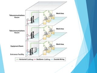
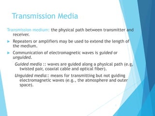
This document provides an overview of structured cabling and transmission media. It discusses different types of transmission media including twisted pair, coaxial cable, and optical fiber. It describes the characteristics of each medium and when each is typically used. It also covers structured cabling systems and the key subsystems including entrance facilities, equipment rooms, telecommunications rooms, backbone cabling, horizontal cabling, and work area components. The document compares backbone and horizontal cabling and provides examples of installing Ethernet cables.


![14
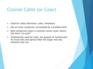
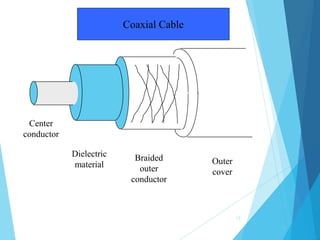
Coaxial Cable
Divided into two basic categories for coax used in
LANs:
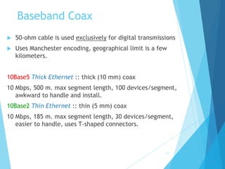
50-ohm cable [baseband]
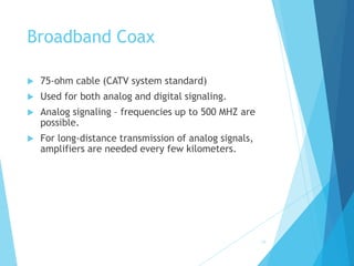
75-ohm cable [broadband or single channel baseband]
In general, coax has better noise immunity for
higher frequencies than twisted pair.
Coaxial cable provides much higher bandwidth than
twisted pair.
However, cable is ‘bulky’.](https://image.slidesharecdn.com/lesson7-structuredcabling-220719190902-9668990c/85/Lesson-7-Structured-cabling-ppt-14-320.jpg)