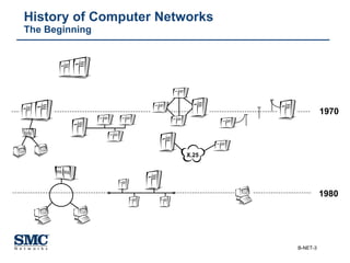
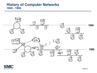
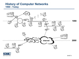
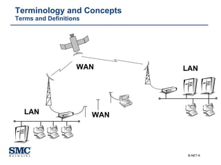
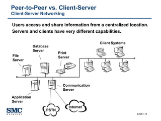
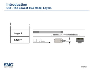
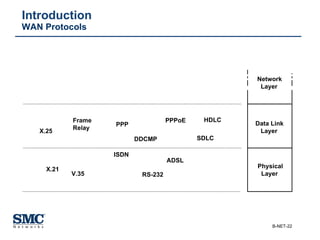
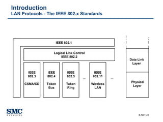
SlideShare a Scribd company logo
Networking Basics
Fundamentals and OSI Model
History of Computer Networks The Beginning 1970 1980 X.25
History of Computer Networks 1980 - 1990 1990 1980 X.25
History of Computer Networks 1990 - Today 1990 2000 PSTN Internet GSM ISDN X.25
Terminology and Concepts Terms and Definitions WAN LAN LAN WAN
Terminology and Concepts Packets or Frames Packet Header Packet Trailer Payload or Data Section
Network Architectures and OSI Model Fundamentals Layer n Layer n-1 Layer 1 Layer 2 http://www.smc.com
Network Architectures and OSI Model The OSI Reference Model Layer n Layer n + 1 Layer n Layer n + 1 n + 1  Protocol n  Protocol Application Presentation Session Transport Network Data Link Physical Node A Node B
Network Architectures and OSI Model Networking Protocols Application Presentation Session Transport Network Data Link Physical Node A Node B Application Presentation Session Transport Network Data Link Physical Bits User Data DH NH TH SH PH AH
Network Architectures and OSI Model The Seven OSI Model Layers Application Presentation Session Transport Network Data Link Physical Node A Node B Application Presentation Session Transport Network Data Link Physical http://www.smc.com 011001101110 111001001110 001100011100
Network Topologies Introduction ,[object Object],[object Object],[object Object],[object Object],[object Object]
Network Topologies Mesh or Point-to-Point Topology A B D C E F
Network Topologies Multipoint Topology A B D C E F
Network Topologies Star Topology A B D C F E
Network Topologies Ring Topology A B D C F E
Network Topologies Bus Topology A B D C E F
Peer-to-Peer vs. Client-Server Peer-to-Peer Networking Users share information between each other  in a de-centralized layout. Individual systems have all necessary capabilities. WAN
Peer-to-Peer vs. Client-Server Client-Server Networking Users access and share information from a centralized location.  Servers and clients have very different capabilities. Client Systems File  Server Application  Server Print Server Database Server Communication Server PSTN Internet
The First Two   OSI Model Layers
Introduction OSI - The Lowest Two Model Layers Layer 1 Layer 2 …  00000111011000110111010111 …
Introduction  WAN Protocols Data Link Layer Physical Layer Network Layer ADSL PPPoE X.25 X.21 Frame Relay PPP ISDN V.35 RS-232 HDLC DDCMP SDLC
Introduction  LAN Protocols - The IEEE 802.x Standards IEEE 802.3 CSMA/CD IEEE 802.4 Token Bus IEEE 802.5 Token Ring IEEE 802.11 Wireless LAN Logical Link Control IEEE 802.2 IEEE 802.1 ... ... Data Link Layer Physical Layer
Introduction Transmission Media Types Twisted Pair Cables Fibre Optic Cable Coaxial Cable
Ethernet / IEEE 802.3 The Roots -   The ALOHA Network
[object Object],[object Object],[object Object],[object Object],[object Object],[object Object],Ethernet / IEEE 802.3 History
Ethernet / IEEE 802.3 Topologies / Transmission Medias ,[object Object],[object Object],[object Object],[object Object],[object Object],[object Object],[object Object]
Ethernet / IEEE 802.3 Connector Types   RJ45 Connector BNC Connector Transceiver ST Connector SC Connector VF45 Connector MTRJ Connector
Ethernet / IEEE 802.3 Link Access Control - CSMA/CD Node A Node B Node C Collision
Ethernet / IEEE 802.3 Following Configuration Rules t Node A Node B Maximum „Distance“ / Maximum Delay t Round Trip Propagation Delay
Ethernet / IEEE 802.3 Round Trip Propagation Delay (Ethernet V2.0)
Ethernet  Ethernet Collision Domain Node B Node A Collision ∆ t Repeater
Ethernet / IEEE 802.3 Typical Ethernet Activity Contention slots Idle period Time Transmission period Contention period Frame Frame Frame Frame
Ethernet / IEEE 802.3 Ethernet Addressing F0 - 2E - 25 - 6C - 77 - 3B 48 Bits (6 Octets) 0000  1111  0111  0100  1010  0100  0011  0110  1110  1110  1101  1100 Sequence of bits on the Ethernet The first bit of the data link address distinguishes  multicast addresses from individual addresses 0 - individual address 1 - group address or multicast address, a broadcast address is a special multicast address consisting entirely of 1´s and addresses all stations  on an Ethernet
Ethernet / IEEE 802.3 Ethernet MAC - Media Access Control Data & Padding Destination Address Type 4 Bytes FCS CRC Source Address 14 Bytes 46-1500 Bytes Data & Padding Destination Address Length CRC Source Address Ethernet V2.0 IEEE 802.3 DSAP  SSAP  Control IEEE 802.2 LLC Fields
Fast Ethernet   Introduction t Node A Node B Maximum „Distance“ / Maximum Delay t Round Trip Propagation Delay
Fast Ethernet  Physical Layer 100m (two twisted pairs) 100Base-TX STP (IBM Type-1) 412m half duplex 2000m full duplex 100Base-FX Fiberoptic 62.5/125 100m (all four twisted pairs) 100Base-T4 Category-3/4 UTP 100m (two twisted pairs) 100Base-TX Category-5 UTP Distance IEEE 802.3u Cable Type
Gigabit Ethernet   Introduction Gigabit Ethernet  Switch Gigabit Ethernet  Switch
Gigabit Ethernet  IEEE 802.3z / 802.3ab Physical Layer Source : Sun Microsystems (Sun and Gigabit Ethernet White Paper) 100 m 802.3ab Long-haul Copper 25m 802.3z Short-haul Copper 550m using 850nm laser (SX)  550m using 1300nm laser (LX) 802.3z Multi-mode Fiber  (50 micron) 300m using 850nm laser (SX)  550m using 1300nm laser (LX) 802.3z Multi-mode Fiber  (62.5 micron) 3000m using 1300nm laser (LX) 802.3z Single-mode Fiber  (9 micron) Distance IEEE Cable Type
Gigabit Ethernet  Media Access Control / Frame Format Start-of-Frame Delimiter Preamble 7 octets 1 octet 6 octets 6 octets 2 octets 46 - 1500 octets 4 octets Length / Type Destination Address Source Address Pad (if necessary) Frame Check Sequence Extension Frame Length Value
10 Gigabit Ethernet  Introduction 10 Gigabit Ethernet  Switch Gigabit Ethernet Switch with 10 Gigabit Uplink Power Users 10/100 Ethernet Switch with Gigabit Uplink
10 Gigabit Ethernet  IEEE 802.3ae Physical Layer 10000m (1310nm WWDM PMD) 802.3ae Single-mode Fiber 300m (1310nm WWDM PMD) 802.3ae Multi-mode Fiber 500m (850nm serial PMD)  802.3ae Multi-mode Fiber 40000m (1550nm serial PMD) 802.3ae Single-mode Fiber 10000m (1310nm serial PMD) 802.3ae Single-mode Fiber Distance IEEE Cable Type
10 Gigabit Ethernet  Media Types ,[object Object],[object Object],[object Object],[object Object],[object Object],[object Object],[object Object],[object Object],[object Object],[object Object],[object Object],[object Object]
Token Ring / IEEE 802.5 Introduction Data Flow Token Node A Node B Node C Node D
Token Ring / IEEE 802.5 Topology RI RI RO RO A B D C E F
Token Ring / IEEE 802.5 Link Access Control Data Flow Token Data Frame 2 Data Frame 1 Node A Node B Node C Node D
Token Ring / IEEE 802.5 MAC Frames and Addressing ,[object Object],[object Object],[object Object],[object Object],[object Object],[object Object],[object Object],[object Object]
FDDI (Fibre Distributed Data Interface) Introduction IEEE 802.3 CSMA/CD IEEE 802.11 Wireless LAN Logical Link Control IEEE 802.2 IEEE 802.1 ... ... FDDI IEEE  802.2 Data Link Layer Physical Layer
FDDI (Fibre Distributed Data Interface) Topology A B D C Class A Device Class A Device Class B Device Class B Device Class A Wiring Concentrator Primary Fibre Loop Secondary Fibre Loop
FDDI (Fibre Distributed Data Interface) Error Recovery in a FDDI Network A B Class B Device Class B Device Class A Wiring Concentrator Primary Fibre Loop Secondary Fibre Loop D Class A Device C Class A Device Reconfiguration Reconfiguration
FDDI (Fibre Distributed Data Interface) Topology - Dual Ring of Trees Wiring Concentrator Wiring Concentrator Wiring Concentrator Wiring Concentrator Node Node Node
Wireless Networking Technologies Applications ,[object Object],[object Object],[object Object],[object Object],[object Object],[object Object],[object Object],[object Object]
Wireless Networks Overview Technologies ,[object Object],[object Object],[object Object],[object Object],[object Object],[object Object],[object Object],[object Object],[object Object],[object Object],[object Object],[object Object]
Wireless Networks Overview Scenarios WLAN WPAN WWAN /  WMAN GPRS GSM UMTS PDA Mobile Phone WiMAX / IEEE 802.16 IEEE 802.11 Bluetooth / IEEE 802.15
Wireless Networks Standards - WPAN, WLAN, WMAN IEEE 802.3 CSMA/CD IEEE 802.11 Wireless LAN IEEE 802.15 WPAN / Bluetooth IEEE 802.16 WMAN / WiMAX Logical Link Control IEEE 802.2 IEEE 802.1 ... ... ... Data Link Layer Physical Layer
PSTN / Modem Introduction ISP Access Concentrator Internet PSTN
ISDN Introduction Digital PBX Private Home Company Internet ISDN
[object Object],[object Object],[object Object],[object Object],[object Object],[object Object],[object Object],[object Object],[object Object],ISDN ISDN is more than a „Digital Network“
ISDN Access Interfaces 1.544 Mbps 2.048 Mbps 1.536 Mbps 1.984 Mbps 30B+D 64 (Europe) 23B+D 64 (USA) Primary Rate  Interface  (PRI) 192 kbps 144 kbps 2B+D 16 Basic Rate Interface (BRI) Total  Bit Rate User  Data Rate Structure
Broadband WAN Services Introduction Broadband Internet Access SME Network Infrastructure Internet
Broadband WAN Services  Overview ,[object Object],[object Object],[object Object],[object Object],[object Object],[object Object]
Broadband WAN Services  xDSL - Digital Subscriber Line Subscriber Network Infrastructure xDSL Link xDSL Modem Broadband Router Internet Central Office
Broadband WAN Services  Cable Modem Solutions Internet Cable Network Headend Subscriber Network/TV Infrastructure TV Cable  Modem Broadband Router Cable Network Infrastructure 75Ω Coaxial Cable
Broadband WAN Services  Satellite Communication Subscriber Standard Satellite Dish  Internet ISDN / PSTN
Broadband WAN Services  Wireless (RF) Solutions Subscriber Network Infrastructure Internet
Broadband WAN Services  Utilising the Electrical Power Infrastructure Subscriber Powerline Modem Internet
Layer 2 WAN Protocols PPP - Point to Point Protocol Internet Router or Access Concentrator Local Network WAN Link Modem oder ISDN TA IP Router Application Presentation Session Transport Network Data Link Physical PPP IP Internet
Introduction   Internetworking
Internetworking Overview Internet
Repeater Definition Application Presentation Session Transport Network Data Link Physical Node A Node B Physical Physical Repeater Function Application Presentation Session Transport Network Data Link Physical
Bridge, Switch  Definition Application Presentation Session Transport Network Data Link Physical Node A Node B Bridge Function Data Link Physical Data Link Physical Application Presentation Session Transport Network Data Link Physical
Bridge, Switch Basic Transparent Bridge Operation Bridge 1 2 E D C B A Workstation Seen via Address  Interface A   1 E   2 C   1 D   2 .   . .   .
Bridge, Switch Transparent Bridges - Multiple Paths C B A 2 1 2 1 2 1 F G   Source    Address F LAN 1 LAN 2
Bridge, Switch The Spanning Tree Protocol In this example the link on bridge C  pointing in direction of  bridge A  is being turned off D Bridge E becomes Root Bridge E A C B Bridge B becomes Designated  Bridge on the “blue” LAN
Router  Definition Application Presentation Session Transport Network Data Link Physical Node A Node B Data Link Physical Network Data Link Physical Network Router Function Application Presentation Session Transport Network Data Link Physical
Router Routing Protocols Node/Network Shortest / Best Path 1 2 1 2 1 2 3 4 1 2 3 1 A B C D E 2 3
Router Routing Protocols - Examples ,[object Object],[object Object],[object Object],[object Object],[object Object],[object Object],[object Object],[object Object]
Gateway  Definition Application Presentation Session Transport Network Data Link Physical Node A Node B Presentation Transmission Path Control Data Link Physical Application Presentation Session Transport Network Data Link Physical Application Transaction Data Flow Presentation Transmission Path Control Data Link Physical Application Transaction Data Flow Gateway Function
Architectures and Protocol Suites Examples ,[object Object],[object Object],[object Object],[object Object],[object Object],[object Object],[object Object],[object Object],[object Object]
Netw. Architectures and Protocol Suites TCP/IP Application Presentation Session Transport Network Data Link Physical OSI Reference Model Application Layer Host-to-Host or Transport Layer Internet Layer Network Access or Local Network Layer TCP/IP Functional Layers
Netw. Architectures and Protocol Suites AppleTalk Application Presentation Session Transport Network Data Link Physical OSI Reference Model AppleTalk Protocol Suite DDP Local Talk Ether Talk Token Talk … RTMP ATP NBP AEP ADSP PAP ASP ZIP AFP Post- Script
Netw. Architectures and Protocol Suites DECnet / DNA Application Presentation Session Transport Network Data Link Physical OSI Reference Model DECnet Phase IV Protocol Suite User Layer Physical Layer Data Link layer Routing Layer End-to-End  Communication Layer Session Layer Network Application Layer
Netw. Architectures and Protocol Suites Novell NetWare (IPX/SPX) Application Presentation Session Transport Network Data Link Physical OSI Reference Model Novell NetWare Protocol Suite Link Support Layer Ethernet Other FDDI IP IPX SPX TCP UD P Netware Services NCP
Netw. Architectures and Protocol Suites Windows NT Network Architecture Application Presentation Session Transport Network Data Link Physical OSI Reference Model Windows NT Network Architecture NDIS Ethernet IP IPX SPX TCP UDP Workstation Services NetBEUI DLC Server FDDI Token Ring Other

More Related Content

What's hot

X.25 and frame relay
X.25 and frame relayX.25 and frame relay
X.25 and frame relay
Tharindu Darshana
 
Networking and internetworking devices
Networking and internetworking devicesNetworking and internetworking devices
Networking and internetworking devices
Raveena kumari
 
Computer Networks Unit 1 Introduction and Physical Layer
Computer Networks Unit 1 Introduction and Physical Layer Computer Networks Unit 1 Introduction and Physical Layer
Computer Networks Unit 1 Introduction and Physical Layer
Dr. SELVAGANESAN S
 
Ethernet Computer network
Ethernet Computer networkEthernet Computer network
Ethernet Computer network
miteshppt
 
Internetworking
InternetworkingInternetworking
InternetworkingRaghu nath
 
What is Ethernet
What is EthernetWhat is Ethernet
What is Ethernet
Simplilearn
 
Physical layer OSI Model & Transmission Media
Physical layer OSI Model & Transmission MediaPhysical layer OSI Model & Transmission Media
Physical layer OSI Model & Transmission Media
Mukesh Chinta
 
Data link layer
Data link layer Data link layer
Data link layer
Mukesh Chinta
 
OSI Physical Layer
OSI Physical LayerOSI Physical Layer
OSI Physical Layer
Sachii Dosti
 
Interconnecting devies
Interconnecting deviesInterconnecting devies
Interconnecting devies
SARAVANAN GOPALAKRISHNAN
 
Osi
OsiOsi
Transport layer
Transport layerTransport layer
Transport layer
reshmadayma
 
Wi-Fi For Beginners - Module 3 - Access Points (APs)
Wi-Fi For Beginners - Module 3 - Access Points (APs)Wi-Fi For Beginners - Module 3 - Access Points (APs)
Wi-Fi For Beginners - Module 3 - Access Points (APs)
Nigel Bowden
 
Ethernet
EthernetEthernet
Physical layer ppt
Physical layer pptPhysical layer ppt
Physical layer ppt
Najam Khattak
 
Token bus
Token busToken bus
Token bus
Denver Rockfreak
 
Osi model
Osi modelOsi model
Osi model
dhawal mehta
 
Computer networking
Computer networkingComputer networking
Computer networking
Maulik Togadiya
 
Transport Layer
Transport LayerTransport Layer
Transport Layer
Ram Dutt Shukla
 

What's hot (20)

X.25 and frame relay
X.25 and frame relayX.25 and frame relay
X.25 and frame relay
 
Networking and internetworking devices
Networking and internetworking devicesNetworking and internetworking devices
Networking and internetworking devices
 
Computer Networks Unit 1 Introduction and Physical Layer
Computer Networks Unit 1 Introduction and Physical Layer Computer Networks Unit 1 Introduction and Physical Layer
Computer Networks Unit 1 Introduction and Physical Layer
 
Ethernet Computer network
Ethernet Computer networkEthernet Computer network
Ethernet Computer network
 
Osi model
Osi modelOsi model
Osi model
 
Internetworking
InternetworkingInternetworking
Internetworking
 
What is Ethernet
What is EthernetWhat is Ethernet
What is Ethernet
 
Physical layer OSI Model & Transmission Media
Physical layer OSI Model & Transmission MediaPhysical layer OSI Model & Transmission Media
Physical layer OSI Model & Transmission Media
 
Data link layer
Data link layer Data link layer
Data link layer
 
OSI Physical Layer
OSI Physical LayerOSI Physical Layer
OSI Physical Layer
 
Interconnecting devies
Interconnecting deviesInterconnecting devies
Interconnecting devies
 
Osi
OsiOsi
Osi
 
Transport layer
Transport layerTransport layer
Transport layer
 
Wi-Fi For Beginners - Module 3 - Access Points (APs)
Wi-Fi For Beginners - Module 3 - Access Points (APs)Wi-Fi For Beginners - Module 3 - Access Points (APs)
Wi-Fi For Beginners - Module 3 - Access Points (APs)
 
Ethernet
EthernetEthernet
Ethernet
 
Physical layer ppt
Physical layer pptPhysical layer ppt
Physical layer ppt
 
Token bus
Token busToken bus
Token bus
 
Osi model
Osi modelOsi model
Osi model
 
Computer networking
Computer networkingComputer networking
Computer networking
 
Transport Layer
Transport LayerTransport Layer
Transport Layer
 

Viewers also liked

Physical Layer of ISO-OSI model and Devices
Physical Layer of ISO-OSI model and DevicesPhysical Layer of ISO-OSI model and Devices
Physical Layer of ISO-OSI model and Devices
Shahid Khan
 
Basics of Connectors
Basics of ConnectorsBasics of Connectors
Basics of Connectors
Pantech ProLabs India Pvt Ltd
 
Visual ip subnetting
Visual ip subnettingVisual ip subnetting
Visual ip subnetting
SMC Networks Europe
 
Chapter 2 Networking
Chapter 2 NetworkingChapter 2 Networking
Chapter 2 Networkingmlrbrown
 
Basics Of Comuter Networking
Basics Of Comuter NetworkingBasics Of Comuter Networking
Basics Of Comuter Networking
anishgoel
 
WP1 Gateway HW Design & Implementation
WP1 Gateway HW Design & ImplementationWP1 Gateway HW Design & Implementation
WP1 Gateway HW Design & Implementation
AGILE IoT
 
UL Consumer Technology
UL Consumer TechnologyUL Consumer Technology
UL Consumer TechnologyKeith Gilbert
 
Brief introduction of wi max technology
Brief introduction of wi max technologyBrief introduction of wi max technology
Brief introduction of wi max technology
Md. Tamim Haider
 
Wireless Sensors and Control Networks
Wireless Sensors and Control NetworksWireless Sensors and Control Networks
Wireless Sensors and Control Networks
Eric Salviac
 
Advantages of cctv camera
Advantages of cctv cameraAdvantages of cctv camera
Advantages of cctv camera
Brihaspathi Technologies
 
Complete Osi Model Explained
Complete Osi Model ExplainedComplete Osi Model Explained
Complete Osi Model Explained
Vivek chan
 
TCP/IP Basics
TCP/IP BasicsTCP/IP Basics
TCP/IP Basics
SMC Networks Europe
 
LTM essentials
LTM essentialsLTM essentials
LTM essentialsbharadwajv
 
Tutorial on IEEE 802.15.4e standard
Tutorial on IEEE 802.15.4e standardTutorial on IEEE 802.15.4e standard
Tutorial on IEEE 802.15.4e standard
Giuseppe Anastasi
 
Ch7
Ch7Ch7
Xprize Think Tank Phoenix IoT Presentation 4/18/16
Xprize Think Tank Phoenix IoT Presentation 4/18/16Xprize Think Tank Phoenix IoT Presentation 4/18/16
Xprize Think Tank Phoenix IoT Presentation 4/18/16
Mark Goldstein
 
wireless energy meter monitoring with automatic tariff calculation ppt
wireless energy meter monitoring with automatic tariff calculation pptwireless energy meter monitoring with automatic tariff calculation ppt
wireless energy meter monitoring with automatic tariff calculation ppt
sheefa kauser
 
Osi model 7 Layers
Osi model 7 LayersOsi model 7 Layers
Osi model 7 Layers
Siddique Ibrahim
 
F5 study guide
F5 study guideF5 study guide
F5 study guideshimera123
 

Viewers also liked (20)

Physical Layer of ISO-OSI model and Devices
Physical Layer of ISO-OSI model and DevicesPhysical Layer of ISO-OSI model and Devices
Physical Layer of ISO-OSI model and Devices
 
IEEE Standards
IEEE StandardsIEEE Standards
IEEE Standards
 
Basics of Connectors
Basics of ConnectorsBasics of Connectors
Basics of Connectors
 
Visual ip subnetting
Visual ip subnettingVisual ip subnetting
Visual ip subnetting
 
Chapter 2 Networking
Chapter 2 NetworkingChapter 2 Networking
Chapter 2 Networking
 
Basics Of Comuter Networking
Basics Of Comuter NetworkingBasics Of Comuter Networking
Basics Of Comuter Networking
 
WP1 Gateway HW Design & Implementation
WP1 Gateway HW Design & ImplementationWP1 Gateway HW Design & Implementation
WP1 Gateway HW Design & Implementation
 
UL Consumer Technology
UL Consumer TechnologyUL Consumer Technology
UL Consumer Technology
 
Brief introduction of wi max technology
Brief introduction of wi max technologyBrief introduction of wi max technology
Brief introduction of wi max technology
 
Wireless Sensors and Control Networks
Wireless Sensors and Control NetworksWireless Sensors and Control Networks
Wireless Sensors and Control Networks
 
Advantages of cctv camera
Advantages of cctv cameraAdvantages of cctv camera
Advantages of cctv camera
 
Complete Osi Model Explained
Complete Osi Model ExplainedComplete Osi Model Explained
Complete Osi Model Explained
 
TCP/IP Basics
TCP/IP BasicsTCP/IP Basics
TCP/IP Basics
 
LTM essentials
LTM essentialsLTM essentials
LTM essentials
 
Tutorial on IEEE 802.15.4e standard
Tutorial on IEEE 802.15.4e standardTutorial on IEEE 802.15.4e standard
Tutorial on IEEE 802.15.4e standard
 
Ch7
Ch7Ch7
Ch7
 
Xprize Think Tank Phoenix IoT Presentation 4/18/16
Xprize Think Tank Phoenix IoT Presentation 4/18/16Xprize Think Tank Phoenix IoT Presentation 4/18/16
Xprize Think Tank Phoenix IoT Presentation 4/18/16
 
wireless energy meter monitoring with automatic tariff calculation ppt
wireless energy meter monitoring with automatic tariff calculation pptwireless energy meter monitoring with automatic tariff calculation ppt
wireless energy meter monitoring with automatic tariff calculation ppt
 
Osi model 7 Layers
Osi model 7 LayersOsi model 7 Layers
Osi model 7 Layers
 
F5 study guide
F5 study guideF5 study guide
F5 study guide
 

Similar to Networking Basics

NET1.PPT
NET1.PPTNET1.PPT
NET1.PPT
ssuser50c54b
 
Internetworking Overview
Internetworking OverviewInternetworking Overview
Internetworking Overview
scooby_doo
 
Network Essentials
Network EssentialsNetwork Essentials
Network Essentials
Iffu Slides
 
Local Area Network – Wired LAN
Local Area Network – Wired LANLocal Area Network – Wired LAN
Local Area Network – Wired LAN
Raj vardhan
 
Ethernet 802.3.pptx
Ethernet 802.3.pptxEthernet 802.3.pptx
Ethernet 802.3.pptx
TanveerAthar1
 
Data Communications and Networks IEEE standards
Data Communications and Networks IEEE standardsData Communications and Networks IEEE standards
Data Communications and Networks IEEE standards
Chandrakant Divate
 
CCNA 200-301 Chapter 2-Fundamentals of Ethernet Lans.pptx
CCNA 200-301 Chapter 2-Fundamentals of Ethernet Lans.pptxCCNA 200-301 Chapter 2-Fundamentals of Ethernet Lans.pptx
CCNA 200-301 Chapter 2-Fundamentals of Ethernet Lans.pptx
saththiyans1
 
CCNA Exam 640-802 Version 9.3
CCNA Exam 640-802 Version 9.3CCNA Exam 640-802 Version 9.3
CCNA Exam 640-802 Version 9.3Ravi Yasas
 
CCNA 200-301 Chapter 2-Fundamentals of Ethernet Lans.pptx
CCNA 200-301 Chapter 2-Fundamentals of Ethernet Lans.pptxCCNA 200-301 Chapter 2-Fundamentals of Ethernet Lans.pptx
CCNA 200-301 Chapter 2-Fundamentals of Ethernet Lans.pptx
BabarYunus1
 
Chap.1 ethernet introduction
Chap.1 ethernet introductionChap.1 ethernet introduction
Chap.1 ethernet introduction
東原 李
 
02 module internet concept overview
02  module internet concept overview02  module internet concept overview
02 module internet concept overview
Asif
 
02 module internet concept overview
02  module internet concept overview02  module internet concept overview
02 module internet concept overviewAsif
 
hardware and software devices for networking
hardware and software devices for networkinghardware and software devices for networking
hardware and software devices for networking
Dhrumil Pandya
 
CCNA 200-301 Chapter 2-Fundamentals of Ethernet Lans.pptx
CCNA 200-301 Chapter 2-Fundamentals of Ethernet Lans.pptxCCNA 200-301 Chapter 2-Fundamentals of Ethernet Lans.pptx
CCNA 200-301 Chapter 2-Fundamentals of Ethernet Lans.pptx
gka092020
 
Basic networking hardware pre final 1
Basic networking hardware pre final 1Basic networking hardware pre final 1
Basic networking hardware pre final 1
Sujee Antony
 
Advanced TCP/IP-based Industrial Networking for Engineers & Technicians
Advanced TCP/IP-based Industrial Networking for Engineers & TechniciansAdvanced TCP/IP-based Industrial Networking for Engineers & Technicians
Advanced TCP/IP-based Industrial Networking for Engineers & Technicians
Living Online
 
Networks (Distributed computing)
Networks (Distributed computing)Networks (Distributed computing)
Networks (Distributed computing)Sri Prasanna
 
Mobile Communication
Mobile CommunicationMobile Communication
Mobile Communication
Kathirvel Ayyaswamy
 
IEEE standards 802.3.&802.11
IEEE standards 802.3.&802.11IEEE standards 802.3.&802.11
IEEE standards 802.3.&802.11
Keshav Maheshwari
 

Similar to Networking Basics (20)

NET1.PPT
NET1.PPTNET1.PPT
NET1.PPT
 
Internetworking Overview
Internetworking OverviewInternetworking Overview
Internetworking Overview
 
Network Essentials
Network EssentialsNetwork Essentials
Network Essentials
 
Local Area Network – Wired LAN
Local Area Network – Wired LANLocal Area Network – Wired LAN
Local Area Network – Wired LAN
 
Ethernet 802.3.pptx
Ethernet 802.3.pptxEthernet 802.3.pptx
Ethernet 802.3.pptx
 
Data Communications and Networks IEEE standards
Data Communications and Networks IEEE standardsData Communications and Networks IEEE standards
Data Communications and Networks IEEE standards
 
CCNA 200-301 Chapter 2-Fundamentals of Ethernet Lans.pptx
CCNA 200-301 Chapter 2-Fundamentals of Ethernet Lans.pptxCCNA 200-301 Chapter 2-Fundamentals of Ethernet Lans.pptx
CCNA 200-301 Chapter 2-Fundamentals of Ethernet Lans.pptx
 
CCNA Exam 640-802 Version 9.3
CCNA Exam 640-802 Version 9.3CCNA Exam 640-802 Version 9.3
CCNA Exam 640-802 Version 9.3
 
CCNA 200-301 Chapter 2-Fundamentals of Ethernet Lans.pptx
CCNA 200-301 Chapter 2-Fundamentals of Ethernet Lans.pptxCCNA 200-301 Chapter 2-Fundamentals of Ethernet Lans.pptx
CCNA 200-301 Chapter 2-Fundamentals of Ethernet Lans.pptx
 
Ethernet_Networks
Ethernet_NetworksEthernet_Networks
Ethernet_Networks
 
Chap.1 ethernet introduction
Chap.1 ethernet introductionChap.1 ethernet introduction
Chap.1 ethernet introduction
 
02 module internet concept overview
02  module internet concept overview02  module internet concept overview
02 module internet concept overview
 
02 module internet concept overview
02  module internet concept overview02  module internet concept overview
02 module internet concept overview
 
hardware and software devices for networking
hardware and software devices for networkinghardware and software devices for networking
hardware and software devices for networking
 
CCNA 200-301 Chapter 2-Fundamentals of Ethernet Lans.pptx
CCNA 200-301 Chapter 2-Fundamentals of Ethernet Lans.pptxCCNA 200-301 Chapter 2-Fundamentals of Ethernet Lans.pptx
CCNA 200-301 Chapter 2-Fundamentals of Ethernet Lans.pptx
 
Basic networking hardware pre final 1
Basic networking hardware pre final 1Basic networking hardware pre final 1
Basic networking hardware pre final 1
 
Advanced TCP/IP-based Industrial Networking for Engineers & Technicians
Advanced TCP/IP-based Industrial Networking for Engineers & TechniciansAdvanced TCP/IP-based Industrial Networking for Engineers & Technicians
Advanced TCP/IP-based Industrial Networking for Engineers & Technicians
 
Networks (Distributed computing)
Networks (Distributed computing)Networks (Distributed computing)
Networks (Distributed computing)
 
Mobile Communication
Mobile CommunicationMobile Communication
Mobile Communication
 
IEEE standards 802.3.&802.11
IEEE standards 802.3.&802.11IEEE standards 802.3.&802.11
IEEE standards 802.3.&802.11
 

Recently uploaded

Builder.ai Founder Sachin Dev Duggal's Strategic Approach to Create an Innova...
Builder.ai Founder Sachin Dev Duggal's Strategic Approach to Create an Innova...Builder.ai Founder Sachin Dev Duggal's Strategic Approach to Create an Innova...
Builder.ai Founder Sachin Dev Duggal's Strategic Approach to Create an Innova...
Ramesh Iyer
 
Mission to Decommission: Importance of Decommissioning Products to Increase E...
Mission to Decommission: Importance of Decommissioning Products to Increase E...Mission to Decommission: Importance of Decommissioning Products to Increase E...
Mission to Decommission: Importance of Decommissioning Products to Increase E...
Product School
 
FIDO Alliance Osaka Seminar: Passkeys at Amazon.pdf
FIDO Alliance Osaka Seminar: Passkeys at Amazon.pdfFIDO Alliance Osaka Seminar: Passkeys at Amazon.pdf
FIDO Alliance Osaka Seminar: Passkeys at Amazon.pdf
FIDO Alliance
 
Generating a custom Ruby SDK for your web service or Rails API using Smithy
Generating a custom Ruby SDK for your web service or Rails API using SmithyGenerating a custom Ruby SDK for your web service or Rails API using Smithy
Generating a custom Ruby SDK for your web service or Rails API using Smithy
g2nightmarescribd
 
When stars align: studies in data quality, knowledge graphs, and machine lear...
When stars align: studies in data quality, knowledge graphs, and machine lear...When stars align: studies in data quality, knowledge graphs, and machine lear...
When stars align: studies in data quality, knowledge graphs, and machine lear...
Elena Simperl
 
GenAISummit 2024 May 28 Sri Ambati Keynote: AGI Belongs to The Community in O...
GenAISummit 2024 May 28 Sri Ambati Keynote: AGI Belongs to The Community in O...GenAISummit 2024 May 28 Sri Ambati Keynote: AGI Belongs to The Community in O...
GenAISummit 2024 May 28 Sri Ambati Keynote: AGI Belongs to The Community in O...
Sri Ambati
 
Securing your Kubernetes cluster_ a step-by-step guide to success !
Securing your Kubernetes cluster_ a step-by-step guide to success !Securing your Kubernetes cluster_ a step-by-step guide to success !
Securing your Kubernetes cluster_ a step-by-step guide to success !
KatiaHIMEUR1
 
FIDO Alliance Osaka Seminar: The WebAuthn API and Discoverable Credentials.pdf
FIDO Alliance Osaka Seminar: The WebAuthn API and Discoverable Credentials.pdfFIDO Alliance Osaka Seminar: The WebAuthn API and Discoverable Credentials.pdf
FIDO Alliance Osaka Seminar: The WebAuthn API and Discoverable Credentials.pdf
FIDO Alliance
 
Slack (or Teams) Automation for Bonterra Impact Management (fka Social Soluti...
Slack (or Teams) Automation for Bonterra Impact Management (fka Social Soluti...Slack (or Teams) Automation for Bonterra Impact Management (fka Social Soluti...
Slack (or Teams) Automation for Bonterra Impact Management (fka Social Soluti...
Jeffrey Haguewood
 
Monitoring Java Application Security with JDK Tools and JFR Events
Monitoring Java Application Security with JDK Tools and JFR EventsMonitoring Java Application Security with JDK Tools and JFR Events
Monitoring Java Application Security with JDK Tools and JFR Events
Ana-Maria Mihalceanu
 
UiPath Test Automation using UiPath Test Suite series, part 4
UiPath Test Automation using UiPath Test Suite series, part 4UiPath Test Automation using UiPath Test Suite series, part 4
UiPath Test Automation using UiPath Test Suite series, part 4
DianaGray10
 
From Daily Decisions to Bottom Line: Connecting Product Work to Revenue by VP...
From Daily Decisions to Bottom Line: Connecting Product Work to Revenue by VP...From Daily Decisions to Bottom Line: Connecting Product Work to Revenue by VP...
From Daily Decisions to Bottom Line: Connecting Product Work to Revenue by VP...
Product School
 
Knowledge engineering: from people to machines and back
Knowledge engineering: from people to machines and backKnowledge engineering: from people to machines and back
Knowledge engineering: from people to machines and back
Elena Simperl
 
Empowering NextGen Mobility via Large Action Model Infrastructure (LAMI): pav...
Empowering NextGen Mobility via Large Action Model Infrastructure (LAMI): pav...Empowering NextGen Mobility via Large Action Model Infrastructure (LAMI): pav...
Empowering NextGen Mobility via Large Action Model Infrastructure (LAMI): pav...
Thierry Lestable
 
Epistemic Interaction - tuning interfaces to provide information for AI support
Epistemic Interaction - tuning interfaces to provide information for AI supportEpistemic Interaction - tuning interfaces to provide information for AI support
Epistemic Interaction - tuning interfaces to provide information for AI support
Alan Dix
 
Leading Change strategies and insights for effective change management pdf 1.pdf
Leading Change strategies and insights for effective change management pdf 1.pdfLeading Change strategies and insights for effective change management pdf 1.pdf
Leading Change strategies and insights for effective change management pdf 1.pdf
OnBoard
 
Assuring Contact Center Experiences for Your Customers With ThousandEyes
Assuring Contact Center Experiences for Your Customers With ThousandEyesAssuring Contact Center Experiences for Your Customers With ThousandEyes
Assuring Contact Center Experiences for Your Customers With ThousandEyes
ThousandEyes
 
Neuro-symbolic is not enough, we need neuro-*semantic*
Neuro-symbolic is not enough, we need neuro-*semantic*Neuro-symbolic is not enough, we need neuro-*semantic*
Neuro-symbolic is not enough, we need neuro-*semantic*
Frank van Harmelen
 
FIDO Alliance Osaka Seminar: Overview.pdf
FIDO Alliance Osaka Seminar: Overview.pdfFIDO Alliance Osaka Seminar: Overview.pdf
FIDO Alliance Osaka Seminar: Overview.pdf
FIDO Alliance
 
Bits & Pixels using AI for Good.........
Bits & Pixels using AI for Good.........Bits & Pixels using AI for Good.........
Bits & Pixels using AI for Good.........
Alison B. Lowndes
 

Recently uploaded (20)

Builder.ai Founder Sachin Dev Duggal's Strategic Approach to Create an Innova...
Builder.ai Founder Sachin Dev Duggal's Strategic Approach to Create an Innova...Builder.ai Founder Sachin Dev Duggal's Strategic Approach to Create an Innova...
Builder.ai Founder Sachin Dev Duggal's Strategic Approach to Create an Innova...
 
Mission to Decommission: Importance of Decommissioning Products to Increase E...
Mission to Decommission: Importance of Decommissioning Products to Increase E...Mission to Decommission: Importance of Decommissioning Products to Increase E...
Mission to Decommission: Importance of Decommissioning Products to Increase E...
 
FIDO Alliance Osaka Seminar: Passkeys at Amazon.pdf
FIDO Alliance Osaka Seminar: Passkeys at Amazon.pdfFIDO Alliance Osaka Seminar: Passkeys at Amazon.pdf
FIDO Alliance Osaka Seminar: Passkeys at Amazon.pdf
 
Generating a custom Ruby SDK for your web service or Rails API using Smithy
Generating a custom Ruby SDK for your web service or Rails API using SmithyGenerating a custom Ruby SDK for your web service or Rails API using Smithy
Generating a custom Ruby SDK for your web service or Rails API using Smithy
 
When stars align: studies in data quality, knowledge graphs, and machine lear...
When stars align: studies in data quality, knowledge graphs, and machine lear...When stars align: studies in data quality, knowledge graphs, and machine lear...
When stars align: studies in data quality, knowledge graphs, and machine lear...
 
GenAISummit 2024 May 28 Sri Ambati Keynote: AGI Belongs to The Community in O...
GenAISummit 2024 May 28 Sri Ambati Keynote: AGI Belongs to The Community in O...GenAISummit 2024 May 28 Sri Ambati Keynote: AGI Belongs to The Community in O...
GenAISummit 2024 May 28 Sri Ambati Keynote: AGI Belongs to The Community in O...
 
Securing your Kubernetes cluster_ a step-by-step guide to success !
Securing your Kubernetes cluster_ a step-by-step guide to success !Securing your Kubernetes cluster_ a step-by-step guide to success !
Securing your Kubernetes cluster_ a step-by-step guide to success !
 
FIDO Alliance Osaka Seminar: The WebAuthn API and Discoverable Credentials.pdf
FIDO Alliance Osaka Seminar: The WebAuthn API and Discoverable Credentials.pdfFIDO Alliance Osaka Seminar: The WebAuthn API and Discoverable Credentials.pdf
FIDO Alliance Osaka Seminar: The WebAuthn API and Discoverable Credentials.pdf
 
Slack (or Teams) Automation for Bonterra Impact Management (fka Social Soluti...
Slack (or Teams) Automation for Bonterra Impact Management (fka Social Soluti...Slack (or Teams) Automation for Bonterra Impact Management (fka Social Soluti...
Slack (or Teams) Automation for Bonterra Impact Management (fka Social Soluti...
 
Monitoring Java Application Security with JDK Tools and JFR Events
Monitoring Java Application Security with JDK Tools and JFR EventsMonitoring Java Application Security with JDK Tools and JFR Events
Monitoring Java Application Security with JDK Tools and JFR Events
 
UiPath Test Automation using UiPath Test Suite series, part 4
UiPath Test Automation using UiPath Test Suite series, part 4UiPath Test Automation using UiPath Test Suite series, part 4
UiPath Test Automation using UiPath Test Suite series, part 4
 
From Daily Decisions to Bottom Line: Connecting Product Work to Revenue by VP...
From Daily Decisions to Bottom Line: Connecting Product Work to Revenue by VP...From Daily Decisions to Bottom Line: Connecting Product Work to Revenue by VP...
From Daily Decisions to Bottom Line: Connecting Product Work to Revenue by VP...
 
Knowledge engineering: from people to machines and back
Knowledge engineering: from people to machines and backKnowledge engineering: from people to machines and back
Knowledge engineering: from people to machines and back
 
Empowering NextGen Mobility via Large Action Model Infrastructure (LAMI): pav...
Empowering NextGen Mobility via Large Action Model Infrastructure (LAMI): pav...Empowering NextGen Mobility via Large Action Model Infrastructure (LAMI): pav...
Empowering NextGen Mobility via Large Action Model Infrastructure (LAMI): pav...
 
Epistemic Interaction - tuning interfaces to provide information for AI support
Epistemic Interaction - tuning interfaces to provide information for AI supportEpistemic Interaction - tuning interfaces to provide information for AI support
Epistemic Interaction - tuning interfaces to provide information for AI support
 
Leading Change strategies and insights for effective change management pdf 1.pdf
Leading Change strategies and insights for effective change management pdf 1.pdfLeading Change strategies and insights for effective change management pdf 1.pdf
Leading Change strategies and insights for effective change management pdf 1.pdf
 
Assuring Contact Center Experiences for Your Customers With ThousandEyes
Assuring Contact Center Experiences for Your Customers With ThousandEyesAssuring Contact Center Experiences for Your Customers With ThousandEyes
Assuring Contact Center Experiences for Your Customers With ThousandEyes
 
Neuro-symbolic is not enough, we need neuro-*semantic*
Neuro-symbolic is not enough, we need neuro-*semantic*Neuro-symbolic is not enough, we need neuro-*semantic*
Neuro-symbolic is not enough, we need neuro-*semantic*
 
FIDO Alliance Osaka Seminar: Overview.pdf
FIDO Alliance Osaka Seminar: Overview.pdfFIDO Alliance Osaka Seminar: Overview.pdf
FIDO Alliance Osaka Seminar: Overview.pdf
 
Bits & Pixels using AI for Good.........
Bits & Pixels using AI for Good.........Bits & Pixels using AI for Good.........
Bits & Pixels using AI for Good.........
 

Networking Basics

  • 3. History of Computer Networks The Beginning 1970 1980 X.25
  • 4. History of Computer Networks 1980 - 1990 1990 1980 X.25
  • 5. History of Computer Networks 1990 - Today 1990 2000 PSTN Internet GSM ISDN X.25
  • 6. Terminology and Concepts Terms and Definitions WAN LAN LAN WAN
  • 7. Terminology and Concepts Packets or Frames Packet Header Packet Trailer Payload or Data Section
  • 8. Network Architectures and OSI Model Fundamentals Layer n Layer n-1 Layer 1 Layer 2 http://www.smc.com
  • 9. Network Architectures and OSI Model The OSI Reference Model Layer n Layer n + 1 Layer n Layer n + 1 n + 1 Protocol n Protocol Application Presentation Session Transport Network Data Link Physical Node A Node B
  • 10. Network Architectures and OSI Model Networking Protocols Application Presentation Session Transport Network Data Link Physical Node A Node B Application Presentation Session Transport Network Data Link Physical Bits User Data DH NH TH SH PH AH
  • 11. Network Architectures and OSI Model The Seven OSI Model Layers Application Presentation Session Transport Network Data Link Physical Node A Node B Application Presentation Session Transport Network Data Link Physical http://www.smc.com 011001101110 111001001110 001100011100
  • 12.
  • 13. Network Topologies Mesh or Point-to-Point Topology A B D C E F
  • 14. Network Topologies Multipoint Topology A B D C E F
  • 15. Network Topologies Star Topology A B D C F E
  • 16. Network Topologies Ring Topology A B D C F E
  • 17. Network Topologies Bus Topology A B D C E F
  • 18. Peer-to-Peer vs. Client-Server Peer-to-Peer Networking Users share information between each other in a de-centralized layout. Individual systems have all necessary capabilities. WAN
  • 19. Peer-to-Peer vs. Client-Server Client-Server Networking Users access and share information from a centralized location. Servers and clients have very different capabilities. Client Systems File Server Application Server Print Server Database Server Communication Server PSTN Internet
  • 20. The First Two OSI Model Layers
  • 21. Introduction OSI - The Lowest Two Model Layers Layer 1 Layer 2 … 00000111011000110111010111 …
  • 22. Introduction WAN Protocols Data Link Layer Physical Layer Network Layer ADSL PPPoE X.25 X.21 Frame Relay PPP ISDN V.35 RS-232 HDLC DDCMP SDLC
  • 23. Introduction LAN Protocols - The IEEE 802.x Standards IEEE 802.3 CSMA/CD IEEE 802.4 Token Bus IEEE 802.5 Token Ring IEEE 802.11 Wireless LAN Logical Link Control IEEE 802.2 IEEE 802.1 ... ... Data Link Layer Physical Layer
  • 24. Introduction Transmission Media Types Twisted Pair Cables Fibre Optic Cable Coaxial Cable
  • 25. Ethernet / IEEE 802.3 The Roots - The ALOHA Network
  • 26.
  • 27.
  • 28. Ethernet / IEEE 802.3 Connector Types RJ45 Connector BNC Connector Transceiver ST Connector SC Connector VF45 Connector MTRJ Connector
  • 29. Ethernet / IEEE 802.3 Link Access Control - CSMA/CD Node A Node B Node C Collision
  • 30. Ethernet / IEEE 802.3 Following Configuration Rules t Node A Node B Maximum „Distance“ / Maximum Delay t Round Trip Propagation Delay
  • 31. Ethernet / IEEE 802.3 Round Trip Propagation Delay (Ethernet V2.0)
  • 32. Ethernet Ethernet Collision Domain Node B Node A Collision ∆ t Repeater
  • 33. Ethernet / IEEE 802.3 Typical Ethernet Activity Contention slots Idle period Time Transmission period Contention period Frame Frame Frame Frame
  • 34. Ethernet / IEEE 802.3 Ethernet Addressing F0 - 2E - 25 - 6C - 77 - 3B 48 Bits (6 Octets) 0000 1111 0111 0100 1010 0100 0011 0110 1110 1110 1101 1100 Sequence of bits on the Ethernet The first bit of the data link address distinguishes multicast addresses from individual addresses 0 - individual address 1 - group address or multicast address, a broadcast address is a special multicast address consisting entirely of 1´s and addresses all stations on an Ethernet
  • 35. Ethernet / IEEE 802.3 Ethernet MAC - Media Access Control Data & Padding Destination Address Type 4 Bytes FCS CRC Source Address 14 Bytes 46-1500 Bytes Data & Padding Destination Address Length CRC Source Address Ethernet V2.0 IEEE 802.3 DSAP SSAP Control IEEE 802.2 LLC Fields
  • 36. Fast Ethernet Introduction t Node A Node B Maximum „Distance“ / Maximum Delay t Round Trip Propagation Delay
  • 37. Fast Ethernet Physical Layer 100m (two twisted pairs) 100Base-TX STP (IBM Type-1) 412m half duplex 2000m full duplex 100Base-FX Fiberoptic 62.5/125 100m (all four twisted pairs) 100Base-T4 Category-3/4 UTP 100m (two twisted pairs) 100Base-TX Category-5 UTP Distance IEEE 802.3u Cable Type
  • 38. Gigabit Ethernet Introduction Gigabit Ethernet Switch Gigabit Ethernet Switch
  • 39. Gigabit Ethernet IEEE 802.3z / 802.3ab Physical Layer Source : Sun Microsystems (Sun and Gigabit Ethernet White Paper) 100 m 802.3ab Long-haul Copper 25m 802.3z Short-haul Copper 550m using 850nm laser (SX) 550m using 1300nm laser (LX) 802.3z Multi-mode Fiber (50 micron) 300m using 850nm laser (SX) 550m using 1300nm laser (LX) 802.3z Multi-mode Fiber (62.5 micron) 3000m using 1300nm laser (LX) 802.3z Single-mode Fiber (9 micron) Distance IEEE Cable Type
  • 40. Gigabit Ethernet Media Access Control / Frame Format Start-of-Frame Delimiter Preamble 7 octets 1 octet 6 octets 6 octets 2 octets 46 - 1500 octets 4 octets Length / Type Destination Address Source Address Pad (if necessary) Frame Check Sequence Extension Frame Length Value
  • 41. 10 Gigabit Ethernet Introduction 10 Gigabit Ethernet Switch Gigabit Ethernet Switch with 10 Gigabit Uplink Power Users 10/100 Ethernet Switch with Gigabit Uplink
  • 42. 10 Gigabit Ethernet IEEE 802.3ae Physical Layer 10000m (1310nm WWDM PMD) 802.3ae Single-mode Fiber 300m (1310nm WWDM PMD) 802.3ae Multi-mode Fiber 500m (850nm serial PMD) 802.3ae Multi-mode Fiber 40000m (1550nm serial PMD) 802.3ae Single-mode Fiber 10000m (1310nm serial PMD) 802.3ae Single-mode Fiber Distance IEEE Cable Type
  • 43.
  • 44. Token Ring / IEEE 802.5 Introduction Data Flow Token Node A Node B Node C Node D
  • 45. Token Ring / IEEE 802.5 Topology RI RI RO RO A B D C E F
  • 46. Token Ring / IEEE 802.5 Link Access Control Data Flow Token Data Frame 2 Data Frame 1 Node A Node B Node C Node D
  • 47.
  • 48. FDDI (Fibre Distributed Data Interface) Introduction IEEE 802.3 CSMA/CD IEEE 802.11 Wireless LAN Logical Link Control IEEE 802.2 IEEE 802.1 ... ... FDDI IEEE 802.2 Data Link Layer Physical Layer
  • 49. FDDI (Fibre Distributed Data Interface) Topology A B D C Class A Device Class A Device Class B Device Class B Device Class A Wiring Concentrator Primary Fibre Loop Secondary Fibre Loop
  • 50. FDDI (Fibre Distributed Data Interface) Error Recovery in a FDDI Network A B Class B Device Class B Device Class A Wiring Concentrator Primary Fibre Loop Secondary Fibre Loop D Class A Device C Class A Device Reconfiguration Reconfiguration
  • 51. FDDI (Fibre Distributed Data Interface) Topology - Dual Ring of Trees Wiring Concentrator Wiring Concentrator Wiring Concentrator Wiring Concentrator Node Node Node
  • 52.
  • 53.
  • 54. Wireless Networks Overview Scenarios WLAN WPAN WWAN / WMAN GPRS GSM UMTS PDA Mobile Phone WiMAX / IEEE 802.16 IEEE 802.11 Bluetooth / IEEE 802.15
  • 55. Wireless Networks Standards - WPAN, WLAN, WMAN IEEE 802.3 CSMA/CD IEEE 802.11 Wireless LAN IEEE 802.15 WPAN / Bluetooth IEEE 802.16 WMAN / WiMAX Logical Link Control IEEE 802.2 IEEE 802.1 ... ... ... Data Link Layer Physical Layer
  • 56. PSTN / Modem Introduction ISP Access Concentrator Internet PSTN
  • 57. ISDN Introduction Digital PBX Private Home Company Internet ISDN
  • 58.
  • 59. ISDN Access Interfaces 1.544 Mbps 2.048 Mbps 1.536 Mbps 1.984 Mbps 30B+D 64 (Europe) 23B+D 64 (USA) Primary Rate Interface (PRI) 192 kbps 144 kbps 2B+D 16 Basic Rate Interface (BRI) Total Bit Rate User Data Rate Structure
  • 60. Broadband WAN Services Introduction Broadband Internet Access SME Network Infrastructure Internet
  • 61.
  • 62. Broadband WAN Services xDSL - Digital Subscriber Line Subscriber Network Infrastructure xDSL Link xDSL Modem Broadband Router Internet Central Office
  • 63. Broadband WAN Services Cable Modem Solutions Internet Cable Network Headend Subscriber Network/TV Infrastructure TV Cable Modem Broadband Router Cable Network Infrastructure 75Ω Coaxial Cable
  • 64. Broadband WAN Services Satellite Communication Subscriber Standard Satellite Dish Internet ISDN / PSTN
  • 65. Broadband WAN Services Wireless (RF) Solutions Subscriber Network Infrastructure Internet
  • 66. Broadband WAN Services Utilising the Electrical Power Infrastructure Subscriber Powerline Modem Internet
  • 67. Layer 2 WAN Protocols PPP - Point to Point Protocol Internet Router or Access Concentrator Local Network WAN Link Modem oder ISDN TA IP Router Application Presentation Session Transport Network Data Link Physical PPP IP Internet
  • 68. Introduction Internetworking
  • 70. Repeater Definition Application Presentation Session Transport Network Data Link Physical Node A Node B Physical Physical Repeater Function Application Presentation Session Transport Network Data Link Physical
  • 71. Bridge, Switch Definition Application Presentation Session Transport Network Data Link Physical Node A Node B Bridge Function Data Link Physical Data Link Physical Application Presentation Session Transport Network Data Link Physical
  • 72. Bridge, Switch Basic Transparent Bridge Operation Bridge 1 2 E D C B A Workstation Seen via Address Interface A 1 E 2 C 1 D 2 . . . .
  • 73. Bridge, Switch Transparent Bridges - Multiple Paths C B A 2 1 2 1 2 1 F G Source Address F LAN 1 LAN 2
  • 74. Bridge, Switch The Spanning Tree Protocol In this example the link on bridge C pointing in direction of bridge A is being turned off D Bridge E becomes Root Bridge E A C B Bridge B becomes Designated Bridge on the “blue” LAN
  • 75. Router Definition Application Presentation Session Transport Network Data Link Physical Node A Node B Data Link Physical Network Data Link Physical Network Router Function Application Presentation Session Transport Network Data Link Physical
  • 76. Router Routing Protocols Node/Network Shortest / Best Path 1 2 1 2 1 2 3 4 1 2 3 1 A B C D E 2 3
  • 77.
  • 78. Gateway Definition Application Presentation Session Transport Network Data Link Physical Node A Node B Presentation Transmission Path Control Data Link Physical Application Presentation Session Transport Network Data Link Physical Application Transaction Data Flow Presentation Transmission Path Control Data Link Physical Application Transaction Data Flow Gateway Function
  • 79.
  • 80. Netw. Architectures and Protocol Suites TCP/IP Application Presentation Session Transport Network Data Link Physical OSI Reference Model Application Layer Host-to-Host or Transport Layer Internet Layer Network Access or Local Network Layer TCP/IP Functional Layers
  • 81. Netw. Architectures and Protocol Suites AppleTalk Application Presentation Session Transport Network Data Link Physical OSI Reference Model AppleTalk Protocol Suite DDP Local Talk Ether Talk Token Talk … RTMP ATP NBP AEP ADSP PAP ASP ZIP AFP Post- Script
  • 82. Netw. Architectures and Protocol Suites DECnet / DNA Application Presentation Session Transport Network Data Link Physical OSI Reference Model DECnet Phase IV Protocol Suite User Layer Physical Layer Data Link layer Routing Layer End-to-End Communication Layer Session Layer Network Application Layer
  • 83. Netw. Architectures and Protocol Suites Novell NetWare (IPX/SPX) Application Presentation Session Transport Network Data Link Physical OSI Reference Model Novell NetWare Protocol Suite Link Support Layer Ethernet Other FDDI IP IPX SPX TCP UD P Netware Services NCP
  • 84. Netw. Architectures and Protocol Suites Windows NT Network Architecture Application Presentation Session Transport Network Data Link Physical OSI Reference Model Windows NT Network Architecture NDIS Ethernet IP IPX SPX TCP UDP Workstation Services NetBEUI DLC Server FDDI Token Ring Other

Editor's Notes

  1. Computer networking is a very recent phenomenon. Although computer networks have been in use for about 30 years, their impact on our daily life and work increased dramatically in the late 1980´s and early 1990´s with the integration of desktop systems. In the 1960´s the development of mainframes and minicomputers created a technological explosion of ideas concerning the way computers were to be used. Engineers and researchers started developing new applications and techniques for using computers, including the possibility of having computers communicate directly with each other directly over telephone lines. In the early 1970´s new technology to connect computer systems was developed which proved that computer systems could be linked together effectively, using long distance communications media. As technology progressed, several different approaches emerged, each driven by different assumptions and goals. Some approaches primarily addressed the need to connect terminals to central concentrations of computers or mainframes, while others focussed on a flexible interconnection of computers. Due to the increasing complexity and importance of computer networks, computer manufacturers began developing comprehensive network architectures. Examples of such network architectures are IBM´s SNA (Systems Network Architecture), DEC´s DNA (Digital Network Architecture) and TCP/IP.
  2. In the late 1970´s and early 1980´ s, the emergence of several new technologies made the concept of networking both an opportunity and a requirement. The introduction of new local area networking (LAN) and wide area networking (WAN) technologies made the communication between computer systems simpler, faster and more cost-effective. Typical examples for such WAN and LAN technologies are X.25, Ethernet and Token Ring. During the early 1980´s another new concept was introduced: desktop systems and personal computing. With desktop hardware and software becoming cheaper and at the same time more powerful, it became necessary to develop possibilities to integrate these systems into the traditional computing environment. In the mid 1980´s the first “real” networking solutions for desktop systems appeared on the market. At that time these networks were targeted strictly to homogeneous (single vendor) environments. Typical examples of such networks are the early versions of AppleTalk (just for Apple computer systems) and Novell NetWare (just for IBM PCs and compatibles). These early networks for desktop systems have several principles in common. First of all they are mainly based on LAN technology, and second they are typically based on the client-server type of computing. The client-server type of computing permits the desktop system to act as a client in requesting services from other computer systems (servers) across the network.
  3. During the 1980´s and the early 1990´s the trend was clearly to incorporate other systems and architectures into what were formerly homogeneous networks. Novell for example, incorporated networking technology into NetWare that allows Apple Macintosh computers to take part in a Novell NetWare network. Many vendors of computer systems also started to offer protocols like TCP/IP to allow connectivity between systems. The last 10 years brought a lot more consolidation and standardisation in regards of networking hardware and protocols with the Internet becoming the by far largest open WAN infrastructure and TCP/IP as the networking protocol of choice to interconnect computer systems. Also in regards of LAN technology there has been a visible trend towards the more simple and cost effective Ethernet infrastructures, where the demand for more bandwidth led to the development to Fast Ethernet and Gigabit Ethernet technology.
  4. There are a number of basic networking terms and concepts that form the basis of the theory of computer networks: LAN (Local Area Network), WAN (Wide Area Network) Nodes and node addresses Packets (or frames) Different communication media and technologies Internetworking A general problem when dealing with „networking“ in general is the existence of many different networking solutions, technologies, products and concepts. In order to be able to position and compare these different alternatives, it is important to have a basis with which to relate. One way to achieve this is to analyse the overall structure, or in networking terms, the network topology . An other way of understanding and describing different networking solutions is to introduce the very abstract concept of „network architectures“. The so called OSI-Model (or OSI architecture) is typically used as the reference model to describe and compare different networking architectures. Other attempts to describe and explain networking concepts focus on implementation and functional principles and divide networking solutions into client-server or peer-to-peer solutions.
  5. Data being sent between computer systems is broken down into smaller pieces called packets or frames . The specific structure and content of these packets very much depends on the communication technology. In general there is information needed in addition to the to be communicated data to ensure proper delivery of that data. This additional information typically consists of the sender and the receiver address, protocol specific parameters and data that ensures data integrity. Ethernet packets or frames for example are composed of three sections: Packet header - contains information like sending and receiving station and protocol type Payload or data section - holds the to be transmitted data Trailer - contains status information about the packet and error checking information
  6. Already in the early days of networking it became clear that due to the complexity of inter-connecting computers and the steadily changing and improving technology, computer networks would have to be designed in a highly structured way. This overall structure is what we call a network architecture. Definition: A network architecture specifies common communication mechanisms and interfaces that computer systems of different types must adhere to, when passing data between systems. Network architectures are neccessary for several reasons: Communication technolgy is continuously changing A broad variety of operating systems, communication devices and computer hardware exists Network management, error recording and maintenance become simpler tasks when standardized Networks need to be adaptable to different communication situations and requirements To reduce the complexity of their design, most network architectures are built as a set of layers with each layer performing a different function - this means each layer has a specific set of tasks that it has to accomplish.The function of the different layers, their names, and the actual number of layers differ among the network architectures. One reason is that computer networks from different vendors have been designed to solve their specific communication needs.
  7. The Open Systems Interconnection (OSI) model is the basis for a set of international communication standards established by the International Standards Organization (ISO). The OSI Model is an internationally accepted framework of standards for communication between computer systems. The OSI model will help us to get a basic understanding of how network architectures are structured, and will be used as a reference for comparing different architectures. There are two important aspects to be understood about the layers of the OSI model: Each layer communicates with its peer on another node using a specific protocol - and - each layer represents a defined set of services to the layer above it. Within the OSI model there are seven defined layers : Layer 7 - Application Layer Layer 6 - Presentation Layer Layer 5 - Session Layer Layer 4 - Transport Layer Layer 3 - Network Layer Layer 2 - Data Link Layer Layer 1 - Physical Layer
  8. A protocol is simply a set of rules for communicating. This set of rules determines how data is transmitted in a network, such as: How the data will be transmitted Size of the packet Error control Recovery procedures Within a layered network architecture, every layer uses its own specific set of protocols . This is done by adding some control information (header, trailer) to the actual user data. To understand how different protocols at different layers in our network architecture work it is best to look at similar principles when people communicate with each other. A good example is the communication between two people by phone. Certain layers or „levels“ of the communication must use certain protocols to work properly: Telephone line (communication media) Language Syntax Context Conventions of telephone conversations, i.e. only one person talks at a time
  9. The Physical Layer is concerned with the mechanical and electrical (optical, ...) transmissions of signals between computer systems. Physical layer standards control such matters as connector specification, modulation, encoding techniques. The Data Link Layer establishes a communication path over the physical channel, manages access to the communications channel, and ensures the proper transmission of data at this level. The Network Layer has as its most critical function with the allocation and interpretation of network addresses. The Network Layer sets up the path between communicating nodes, routes messages through intervening nodes to their destination, and controls the flow of messages between nodes. The Transport Layer provides end-to-end control of a communication session once the path has been established. This layer allows processes to exchange data reliably and sequentially independent of the systems which are communicating, or their location in the network. Session Layer is concerned with dialogue management. It establishes and controls system dependant aspects of communications sessions. The Presentation Layer masks out the variation in data formats between systems from different vendors. This layer works by transferring data in a system-independent way, performing appr. conversions within each system. The Application Layer provides services that directly support user and application tasks such as file transfer, remote file access and mail.
  10. A computer network can be configured in an almost endless variety of ways. The particular user requirements and chosen media are the most important factors in determining the „shape“ of a network. Despite the variety among networks, there are general categories of network shapes, called topologies. The Topologies are helpful when discussing or comparing various networks and their design goals.
  11. The simplest network structure is based on point-to-point connections. A point-to-point link connects two (and only two) nodes without passing through an intermediate node. A mesh topology is built of just point-to-point links.
  12. In a multipoint configuration, several remote nodes share the same physical link. One node is designated as the control node which asks the other nodes in turn (polling) to send data.
  13. In a star, or centralized network, all nodes communicate via a central node that controls the network. All data flows toward or outward from this central device, node or computer.
  14. In a ring topology the nodes are arranged to form an unbroken circular configuration. Transmitted messages travel from node to node around the ring.
  15. The bus topology works to some extent in the same way as a multipoint network - a single communication media which is shared by a number of nodes. However, in the event of node failures, network operation will continue due to the passive role nodes play in transmissions on the bus. There is no single device or node controlling or prioritising the transmissions.
  16. In peer-to-peer networks users share information between each other in a de-centralized way. Typical advantages of peer-to-peer networks are: Easy to install Inexpensive No dedicated server - no single point of failure Typical disadvantages are: Difficult to manage Limited security Reduced performance as the number of users increases
  17. In client-server networks users access and share information in a centralized way. The asymmetric implementation of functions allow simple less overhead end user applications while concentrating advanced functions in the servers. Typical advantages of client-server networks are: Easy to manage Easy to maintain, backup Good performance Security measures are easily implemented Typical disadvantages are: Dedicated server - single point of failure Management necessary
  18. The lowest two layers of the OSI model are not always easy to separate when it comes to group them into LAN and WAN standards. Most importantly the first two layers build the basis for all protocols of the higher layers by specifying what kind of „language“ is used on what type of media. Many different types of transmission media and access protocols have been and are used in computer networks, ranging from two wire cables to satellite links. Each transmission media uses specially designed protocols that specify how it is to be accessed .
  19. In the early days of data communication computer networks were built upon point-to-point connections (serial lines). Because of the bad quality of the media that were available at that time (i.e. telephone lines) WAN protocols like HDLC and DDCMP were designed to ensure sequencing and integrity of data in the event of transmission errors . The need for more reliable WAN connections then lead to the development and implementation of packet switching networks such as X.25, Frame Relay and ISDN. Many of the WAN standards and specifications are older than the OSI reference model wich makes it often difficult to precisely assign them to a specific OSI model layer. The grouping is relatively easy when it comes to standards and specifications like V.35, RS232, X.21 that describe interfaces and signalling which clearly is OSI Physical Layer related. The same is true for Data Link protocols like PPP, PPPoE or DDCMP – these standards and specifications fulfill exactly the functions described in the OSI Data Link Layer. A clear decision of whether protocols like ISDN, X.25 or Frame Relay should be seen as pure Data Link protocols is somehow difficult. These standards and specifications include many functions, interface descriptions, etc. that could be seen as OSI model layer 1 (for example ISDN signalling) or even OSI model layer 3 (for example addressing and forwarding of packets in X.25, ISDN) related.
  20. In the last 25 years the work place has been filled more and more with increasingly intelligent machines such as personal computers, workstations, scanners, plotters, printers, and so on. These machines assist in carrying out the day to day tasks and communications; therefore there has been an increasing need to interconnect these separate machines within a limited area. This has led to the development of what we call Local Area Networks (LAN). Typical characteristics of LANs are: Limited to a small area (i.e. building, factory, campus) High bandwidth compared to WANs Relatively low cost for high bandwidth Usually owned by the user (company) Due to the fact that lots of different devices and applications from different vendors should be able to access the same media, standardization within the LAN environment was, and is, a crucial issue. Most of the widely used LAN technologies are either part of the ANSI / IEEE 802.x standards or are tightly related to ensure compatibility and easy integration of different LANs.
  21. Transmission media are the physical paths over which information flows from sender to receiver. Transmission refers to the method of carrying data from one place to another. In computer networks a broad range of different media is used, from simple two wire cables to radio or microwaves. There are three main media types used in LANs: Coaxial cables (ARCNet, Ethernet) Shielded / unshielded twisted pair cables (ARCNet, Ethernet, Fast Ethernet, Token Ring, FDDI/CDDI) Fibre optic cables (Ethernet, Fast Ethernet, Gigabit Ethernet, FDDI)
  22. The idea of Ethernet grew out of the packet radio broadcast network, known as the ALOHA network . This system, designed in the early 1970s for the University of Hawaii , used a distributed radio transmission network. The special thing about ALOHA is the fact that it did not use FDM (Frequency Division Multiplexing) which is used by conventional broadcast systems to give each site its own share of the communication bandwidth. Instead it uses a special contention scheme in which a node simply transmits on the single channel when it needs to. If one node is already transmitting, or starts to transmit, while an other node is also beginning to transmit, a „collision“ occurs.These collisions can be detected and retransmits can be initiated. In approximately 1976 the Xerox PARC experimental Ethernet was developed, in which the techniques used for ALOHA were improved and applied to a coaxial cable medium . In 1980 , a new version was introduced in a specification document published jointly by Digital Equipment, Intel and Xerox. This specification, called DIX-Ethernet became then quickly a de facto industry standard. The DIX-Ethernet was later adopted with minor changes and enhancements in the IEEE 802 local area networks standards committee and became the IEEE 802.3 (CSMA/CD) standard .
  23. Connectors typically found in Ethernet installations: AUI (Attachment Unit Interface) used to connect to external transceivers BNC RJ45 SC, ST, VF45, MTRJ An Ethernet transceiver is a device that transmits and receives information to and from the wire. When you plug into an RJ45, BNC or Fiber port on a NIC, you are connecting to a transceiver. Transceivers are also available as an external device that attach to the AUI port of the network computer.
  24. Although there are minor differences between (DIX) Ethernet and IEEE 802.3, both use the same basic scheme, called CSMA/CD to control the access to the communication channel. CSMA/CD is an abbreviation for: CS - Carrier Sense . The node constantly monitors the cable to see if there is any activity on the Ethernet. If some other node is already transmitting, then the node waits (defers its transmission) until the other node has finished transmitting. MA - Multiple Access . Any station connected to the Ethernet can transmit as soon as it is free. This means all nodes have equal access to the communication channel CD - Collision Detection . Most of the time the carrier sense works well, however on occasion, two nodes might start transmitting at the same time. In this case, they both interfere with each others signals and generate a collision. When a collision is detected, the transmission is aborted and started again at a random time.
  25. In order to ensure that all nodes, including the one that is transmitting, are able to detect a collision on the channel, packets must be of a certain minimum length. The minimum time a node has to send (minimum packet length) is called slot time, which is slightly greater than the round trip propagation delay between two furthest points in the network. This is the reason why it is this important to follow the configuration rules to be found in the IEEE 802.3 specifications. The configuration rules are based on a „worst case“ calculation which takes all components causing propagation delays into account. Violation of configuration rules can have severe effects on performance and stability of the Ethernet network.
  26. The Ethernet configuration rules are based on a „worst case“ calculation which takes all components causing propagation delays into account. The above calculation is from the early Ethernet V2.0 spec and is only meant to visualize the calculation.
  27. Ethernet bandwidth is 10Mbps. In an environment using only hubs, the entire network is on a single collision domain . As a consequence of this all users are sharing the 10Mbps bandwidth. As more users connect to the LAN, the number of collisions in the domain rises, and the bandwidth available per user is reduced. This mechanism is called contention . It is also important to remember that an Ethernet collision domain is limited in “size” because of CSMA/CD and therefore Ethernet configuration rules have to be followed precisely.
  28. Ethernet uses CSMA/CD a contention protocol that resolves a collision after it occurs. It executes the collision resolution protocol after each collision. A sending node on the Ethernet attempts to avoid contention with other traffic on the channel by monitoring the carrier sense signal and deferring to passing traffic. When the traffic is clear, the frame transmission is started(after a brief interframe delay). At the receiving station, the arriving frame is detected, synchronizes with the incoming preamble. The frame’s destination address field is checked to decide whether the frame should be received by the station. If yes the contents of the frame is passed to the next higher layer. If multiple stations attempt to transmit at the same time, it is possible that they interfere with each other’s transmissions, in spite of their attempts to avoid this by deferring. When two station’s transmissions overlap, the resulting contention is called a collisison. As soon as a collision is detected the transmission is stopped and attempted after a short delay again. Minimum time a host must transmit for before it can be sure that no other host's packet has collided with its transmission is called contention slot. Typical Ethernet activity therefore shows between the ransmission periods, idle periods (where no transmission is attempted) and contention periods.
  29. Node addressing provides a means of uniquely identifying each node connected to the local area network. An Ethernet address is 48 bits in length. It is represented by six pairs of hexadecimal digits. For example: F0-2E-25-6C-77-3B These digit pairs are typically separated by single hyphens. The order of transmission on the Ethernet is from the leftmost octet to the rightmost octet. The order of bits within the octets is from the least significant bit of the rightmost digit to the most significant bit of the leftmost digit. Normally, one address is permanently associated with each interface. This means that each Ethernet device is manufactured with an unique address stored in ROM. This individual address is called the Hardware Address. These (globally administered) unique addresses are allocated in address blocks to organizations in a centralized manner. SMC for example has the following ranges of addresses (and others) assigned to it: 00-80-0F-xx-xx-xx 00-E0-29-xx-xx-xx There are specific types of addresses that are essential for some of the higher layer protocols: Multicast Address - a multi-destination address ( for one or more nodes) Broadcast Address - a single Multicast address intended for all nodes
  30. Due to the fact that IEEE did introduce some changes to the original Ethernet V2.0 specification, we know today two slightly different Ethernet MAC frames. The MAC Protocol adds address information to the packet, and checks to see that the packet arrives intact. For this purpose the vendor’s hardware address (3 bytes) from the NIC is read. This information is used to create a 6 byte MAC Address. To transmit a packet, the source MAC Address and the destination MAC Address are added to the packet, creating a new packet. This process is called encapsulation . In addition to adding address information, the MAC Protocol also adds: A 2 byte field. In Ethernet V2.0 it contains frame type information that tells the OS what protocol is being used (IP, IPX, etc.) In IEEE 802.3 these 2 bytes specify the length of the data field in bytes. A 4 byte CRC (Cyclic Redundancy Check) field that is used to check for errors in the received data Once the packet is encapsulated, it is send out on the “wire”. As the packet passes by a computer attached to the LAN, the NIC in that computer checks the packet’s destination address. If the packet is addressed to that NIC, the driver copies the packet and the OS decodes the packet and delivers the data to the appropriate application.
  31. Fast Ethernet transmits at 10 times the speed of Ethernet and as with Ethernet, signal loses strength and coherence as it travels the wire. The developers of Fast Ethernet had to ensure compatibility at the frame level with Ethernet. CSMA/CD relies on a minimum time that every station on the network is sending a frame. This is guaranteed by the minimum packet length. The speed of transmission can therefore be increased by decreasing the signal´s worst case round trip delay. This means reducing also the maximum allowed distance between any two stations in the network. As a result the maximum allowed distance between any two stations with Fast Ethernet (copper) is only 205m compared to 2.5km with Ethernet.
  32. The Physical Layer of Fast Ethernet uses a mixture of proven technologies from the original Ethernet and the ANSI FDDI Specification. The physical media types are defined in 802.3u. Fast Ethernet works with category 3,4 and 5 unshielded twisted pair (UTP), type-1 shielded twisted pair (STP), and fiberoptic cables. The Fast Ethernet standard also offers a media-independent interface. This interface is called MII (Media Independent Interface) and performs the same function in Fast Ethernet as the AUI in 10 Mbps Ethernet.
  33. Gigabit Ethernet transmits at 100 times the speed of Ethernet. The developers of Gigabit Ethernet had to ensure compatibility at the frame level with Ethernet and Fast Ethernet. This and the requirement to support still transmission distances that are acceptable results not only in the use of switching technology but also in changed layer one operation. The use of Gigabit Ethernet switches instead of repeaters also means that there are hardly any configuration rules besides maximum cable length to be followed.
  34. The Physical Layer of Gigabit Ethernet uses a mixture of proven technologies from the original Ethernet and the ANSI X3T11 Fibre Channel Specification. The physical media types are defined in 802.3z (1000Base-X) and 802.3ab (1000Base-T). The 1000Base-X standard is based on the Fibre Channel Physical Layer. Fibre Channel is an interconnection technology for connecting workstations, supercomputers, storage devices and peripherals. Three types of media are include in the 1000Base-X standard : 1000Base-SX 850 nm laser on multi mode fiber. 1000Base-LX 1300 nm laser on single mode and multi mode fiber. 1000Base-CX Short haul copper "twinax" STP cable 1000Base-T is a standard for Gigabit Ethernet that utilizes long haul copper UTP. Up to 100m over 4 pairs of Category 5 UTP are possible. Some Gigabit Ethernet switching devices offer a modular standardized media interface called GBIC. The Gigabit interface converter (GBIC) allows the network administrator to configure each gigabit port on a port-by-port basis for short-wave (SX), long-wave (LX), long-haul (LH), and copper physical interfaces (CX).
  35. The developers of Gigabit Ethernet had to ensure compatibility at the frame level with Ethernet . The general structure of a Gigabit Ethernet frame and a 10Mbps or 100Mbps Ethernet frame are identical. Todays Gigabit Ethernet networks are nearly entirely implemented using switched full-duplex connections. But due to the fact that also Gigabit Ethernet was designed to work in ( half duplex ) shared media implementations the developers of the standard had to ensure that the sending station still can sense collisions. CSMA/CD relies on a minimum time that every station on the network is sending a frame. In Ethernet and Fast Ethernet this is guaranteed by the minimum packet length. Because of the speed of transmission with Gigabit Ethernet this would result in a maximum allowed distance between any two stations of only about 10m. In order to overcome this severe length limitation in Gigabit Ethernet the frame length has to be artificially increased by appending an extension field at the end of the frame, right after the frame check sequence (FCS). To minimize the waste of bandwidth introduced with the extension field, the Gigabit Ethernet standard allows the sending station to send a sequence of frames ( frame bursting ) for a pre defined period of time.
  36. 10-Gigabit Ethernet (10GBASE-T) as standardized in IEEE 802.3a, is a telecommunication technology that offers data speeds up to 10 billion bits per second - or - 1000 times the speed of Ethernet. Built on the Ethernet technology used in most of today's LANs, 10-Gigabit Ethernet offers a more efficient and less expensive alternative for backbone connections while also providing a consistent technology end-to-end. 10-Gigabit Ethernet uses the familiar IEEE 802.3 Ethernet media access control (MAC) protocol and its frame format and size. Additionally, this standard is moving away from half-duplex design, with broadcasting to all nodes, towards only supporting switched full-duplex networks. Unlike earlier Ethernet systems, 10-gigabit Ethernet is mainly based on the use of optical fiber connections. However, the IEEE is working on a standard for 10-Gigabit Ethernet over Cat-6 or Cat-7 twisted pair cable.
  37. The IEEE 802.3ae* standard describes a physical layer that supports specific link distances for fiber-optic media. To meet the distance objectives, four PMDs (physical-media-dependent devices) were selected: 1310nm serial 1550nm serial 850nm serial 1310nm WWDM (wide-wave division multiplexing) There are two types of optical fiber, multimode and singlemode fiber, that are currently used in data networking and telecommunications applications. The IEEE 802.3ae* standard, supports both optical fiber types. However, the distances supported vary based on the type of fiber and wavelength (nm) is implemented in the application. IEEE 802.3* has formed two study groups to investigate 10 Gigabit Ethernet over copper cabling. The 10GBASE-CX4 group is working on a standard for transmitting and receiving via a 4-pair twinax- cable. The 10GBASE-T group is working on a standard for the transmission and reception of 10 Gigabit Ethernet via a Category 5 unshielded twisted pair (UTP) copper cable up to 100 m.
  38. 10GBASE-SR ("short range") is designed to cover short distances using existing multi-mode fiber cabling. It has a range of between 26m and 8 m depending on the used cable type. With a new developed multi-mode fiber distances with up to 300m are possible. 10GBASE-CX4 describes a copper interface using twinax-cable ( InfiniBand) for short-reach (15 m maximum) applications. 10GBASE-LX4 uses wavelength division multiplexing to support ranges of between 240m and 300m over d multi-mode cabling and also supports distances of up to 10km over single-mode fiber. 10GBASE-LR (long range) and 10GBASE-ER (extended range) are standards that allow distances of up to 10 km and 40km respectively over single-mode fiber. 10GBASE-LRM describes 10 Gbps on FDDI-grade 62.5 µm multi-mode cable 10GBASE-SW, 10GBASE-LW and 10GBASE-EW use the WAN PHY, designed to interoperate with OC-192/STM-64 SONET/SDH equipment. They relate at the physical layer to 10GBASE-SR, 10GBASE-LR and 10GBASE-ER respecively, and therefore use the same types of fiber and support the same distances.
  39. Already in the 1960s engineers were working on techniques for how to share a communication medium among a number of nodes. One of these techniques was to use a data structure called a „token“ to organize the use of the medium , which is much like a special polling technique. In combination with a ring topology (every node in the network is a repeater which forwards the packets to the next neighbour) this technique seemed to allow an efficient use of communication bandwidth. The first experimental single ring was built at Bell Laboratories, operating at a speed of some 3 Mbps. At that time, a single bit represented what we call the token, and a supervisory computer was used for cleaning up faulty packets from the network. IBM s token ring work in the early 1980s was in large measure responsible for the technical details incorporated into the IEEE 802.5 standard.
  40. Most Token Rings deployed use a star-wired ring as topology, operating at either 4 or 16 Mbps . The most widely used media that are standardized are: Shielded Twisted-Pair (STP) Unshielded Twisted-Pair (UTP) Fibre optic cables are used for RI/RO connections between MAUs (Media Access Units)
  41. Token Ring networks use a special polling method for link access control. Since any node that wishes to transmit must wait to be polled, there is no access contention and there are no access conflicts. The system of using a token specifies that only the node that holds the “token” has the right to transmit data. The following description of the link access method only applies to 4MB/sec Token Ring : The token circulates on the ring until a station that wishes to transmit something captures it. The node that holds the token sends out the data frame and keeps the token. Each node to which the data frame is not addressed, simply passes the frame along by re-transmitting (repeating) it. The destination node reads the frame (while also repeating it) and changes two bits to indicate that the destination address was recognized and the frame copied. Because of the two changed bits in the data frame, the source node receives an acknowledgement of receipt when the frame returns to the source node. The source node then removes the data from the ring an issues a new token. Token ring LANs running at 16 MB/sec use a slightly different method called early token release , when the token is already released after the data frame is transmitted. This means that there is possibly more than one frame on the ring at a time.
  42. Although the basic principles of token ring that have been described above seem to be quite simple, a lot of control, maintenance, and error recovery operations have to be carried out. This is done by special purpose frames called MAC (Media Access Control) frames that are associated with token ring processes like: Ring Insertion Beaconing Neighbour notification Token generation Addresses used on token ring networks are very similar to Ethernet or 802.3 addresses. One fundamental difference is that the bit order (MSB/LSB) is changed. Although the specification also mentions a 16-bit addressing scheme a 48-bit address is used. As with Ethernet it is represented by six pairs of hexadecimal digits. For example: 55-00-02-00-43-1C
  43. Fibre Distributed Data Interface (FDDI) is a local area network standard that was developed under the rules of ANSI (the American National Standards Institute). FDDI has been developed as a high speed (100 MB/sec), fiber optic, general purpose network . Design goals besides high bandwidth were a high level of availability and redundancy. Although the FDDI standard is not a part of the IEEE 802 standards, a high level of compatibility was ensured. IEEE 802.2 Link Level Control is an integral part of both standards. Various other media options were added to the FDDI standard to support also various twisted pair cable alternatives.
  44. Two different station types are defined by the FDDI standard: Class A stations that have two physical connections to the ring - and - Class B stations that have one physical connection to the ring and are used in combination with a wiring concentrator. The FDDI ring is built of a primary fibre loop and a secondary fibre loop , that is only used for backup. Class A stations have connections to both (primary and secondary) loops, while Class B stations are connected only to the primary loop. The wiring concentrator is a special case of the Class A station that allows single connections to Class B stations and is connected to the primary and secondary ring.
  45. If a cable fault or station failure occurs, the FDDI networks starts a reconfiguration to solve the problem.
  46. Larger FDDI networks consist often of several concentrators and nodes which form a basic network technology. This topology is called a “ Dual Ring of Trees ” and provides even more redundant operation for increased reliability.
  47. Quite often communication infrastructures based on standard wiring schemes are not feasible because of cost or technical reasons. In this case wireless products offer flexible alternatives to wired network solutions . Wireless technology also provides excellent solutions where there is a need for temporary networking installations. In many cases where more traditional communication solution cannot be envisioned with conventional wired technologies, wireless technology makes the seemingly impossible quite feasible, easy to implement, and cost effective. Implementing wired infrastructures into existing building structures can present complex problems. Building codes or city ordinances that seek to protect historic buildings from any structural damage can create severe costs and technical problems for the network designer implementing wired technologies.
  48. Today different wireless(mostly RF) technologies have been developed or are under development to address a broad range of wireless communication applications and scenarios. The requirements for these applications are mainly based on a varitey of variables including the needed bandwith, the distances that have to be covered, the geographic reach, power consumption and the kind of services offered. In general we can separate the different wireless technologies into the following categories: Each categoriy shows one (or more) corresponding wireless technologies that solve the specific communication issues of that category or application. Although overlaps (WPAN/WLAN, WLAN/WMAN) exist, the deployed technologies are extremely different and supplement each other to a very high degree.
  49. WPAN (Wireless Personal Area Netwrking) technologies like Bluetooth / / IEEE 802.15 solve connectivity problems between devices and systems in a very limited geographical area. Typical network coverage in the WPAN is up to 10m, the data transfer rates depend on the standards emplyed. Applications are for example the synchronisation of data and file transfers between PDAs, laptops and mobile phones but also the wireless connection of peripherals and devices like head sets, printers, etc. WLAN (Wireless Local Area Networking) applications typically solve wireless data communication problems in an building, enterprize or campus environment. The dominant technology used is absed on the IEEE 802.11 standards. WMAN (Wireless Metropolitan Area Networking) infrastructures are designed to overcome “last mile” access issues by providing wireless connectivity in an metropolitan environment. Example for an emerging WMAN standard is WiMAX (IEEE 802.16) WWAN (Wireless Wide Area Networking) technologies offer wireless mobility solutions, typically offering lower bandwitdth but covering large geographical areas. Typical examples for such technologies are GPRS, UMTS and GSM.
  50. The Bluetooth technology standard was originally deveolperd as an industry standard driven by a group of manufacturers but the standardisation process is now also taken care of by an IEEE working group (802.15). The first version IEEE 802. 15.1 was derived from the original Bluetooth specification and is compatible to Bluetooth V.1.1. This standard supports data rates up to 1Mbps and is primarily used for wireless connectivity with computer peripherals and other devices like printers, headsets, mobile phones and PDAs. IEEE 802.15.3 (also called ultra-wide band or UWB) is designed for much higher speeds and multimedia services. This standard supports speeds up to 400Mbps, allowing the transmission of video (of DVD quality) and audio signals throughout the home. Within the IEEE the 802.11 working group is responsible for developing standards for WirelessLocal Area Networks (WLANs). WLANs typically serve a lot more users than WPANs and cover a larger area. The IEEE 802.11 standard is based on the same framework and principles that also form the basis for Ethernet (IEEE 802.3). This ensures a high level of compatibility and interopearbility between 802.11 and 802.3 devices and infrastructures. Until now three major revisions or versions of the physical layer have been released supporting speeds up to 54Mbps. The Wireless Metropolitan Area Network (WWAN) typically covers areas up to 50km and competes directly with other access technologies like xDSL or (DOCSIS) cable. WiMAX is an example for a new generation of standardized wireless broadband internet access technologyies. WiMAX is aworldwide certification adddressing interoperability issues across IEEE 802.16 products.
  51. The word modem is a contraction of the words modulator-demodulator . A modem is typically used to send digital data over a phone line. The sending modem modulates the data into a signal that is compatible with the phone line, and the receiving modem demodulates the signal back into digital data. Modems came into existence in the 1960s as a way to allow terminals to connect to computers over the phone lines. Once people started transferring large programs and images 300 BPS became intolerable. Modem speeds increased in a series of steps at two year or so intervals: 300 bit per second - 1960s through 1983 or so 1200 bit per second - gained more popularity in 1984 and 1985 2400 bit per second 9600 bit per second - ( late 1990 and early 1991) 19.2K bit per second 28.8K bit per second 33.6K bit per second 56K bit per second - became the standard in 1998 Modems use a hand-shaking sequence to negotiate the best modulation technique supported on both ends of the communication path.
  52. Telephone networks around the world have been evolving toward the use of digital transmission facilities and switches for many years. The CCITT which is largely responsible for today´s international ISDN standards, defines an Integrated Services Digital Network (ISDN) as: “ A network evolved from the telephony Integrated Digital Network (IDN), that provides end-to-end digital connectivity to support a wide variety of services, to which users have access by a limited set of standard multi-purpose user-network interfaces.” In other words, an ISDN is a network designed to carry many different types of data over medium-to-large distances, and between a wide variety of equipment types, such as computers, telephones, facsimile and telex machines. Features and functions associated with ISDN include: End-to-end digital service Standardized access interface Well defined basic services and supplementary services like telephone (voice) 2B+D for small users (B=64 KB/sec, D=16 KB/sec) 23B+D (30B+D) for large users (B=64 KB/sec, D=64 KB/sec)
  53. Standards are the basis for the development of attractively priced communication solutions for large markets. ISDN is more than „Digital Network“. „Integrated Services“ stands for the seamless integration of voice and data . A variety of advanced communication services, tele-services and fast and reliable connections into the Internet or to other remote networks today rely on ISDN. All this and the ability to use two individual communication channels with a single S0 connection explain the flexibility of ISDN. For small and medium-sized enterprises ISDN is very attractive. ISDN delivers to customers attractive tariffs for lines and high quality digital transmission in combination with relatively large bandwidth . ISDN is also available in most European countries . Functions like „dial-on-demand“ or „bandwidth-on-demand“ are only possible because of the short times needed for call establishment when using ISDN. ISDN is also popular because of its built-in security features . Typical examples for such functions are calling line identification or closed user group .
  54. The ISDN standards provide the rules for interfacing with the network , they do not describe the network itself. The standards also describe the services that may be offered by an ISDN. ISDN access interfaces differ somewhat from traditional access interfaces (as in the single line used for the telephone). First, one goal of the ISDN, is to provide all services over a single network connection regardless of equipment or service type. Second, the ISDN access interface comprises different channels for signalling and for data. Currently there are two different access interfaces to the network defined as: The basic rate interface (BRI) The primary rate interface (PRI)
  55. The demand for high performance WAN services - also for small and medium enterprises - grows steadily . Both old and new “bandwidth hungry” applications require more WAN bandwidth. Groupware and other Client Server solutions Multi media solutions Video streaming and video conferencing Internet Access for individual systems and complete LANs The Internet used as company WAN backbone The number of subscribers for broadband services is growing rapidly . Many different tariff models, technological alternatives and attractive pricing attract a large number of users to change their existing Internet access technology to one of the new broadband alternatives. There are a number of important factors causing this fast development: Cost efficient use and upgrade of existing communication infrastructures Standardized products and technologies Competing service providers in most markets A large number of manufacturers of broadband products
  56. There are currently several alternative and competing broadband technologies available or under development. xDSL (Digital Subscriber Line) today clearly has the largest market share of all broadband internet access technologies. Other technologies and solutions have nevertheless also a large growth potential because of the specific features and advantages some of theses technologies offer. Still there are criteria to be met to gain broad market acceptance which are not all met by current xDSL alternatives: Complete geographical coverage Different services and tariff models to optimally solve specific customer requirements Low cost for both subscriber and service provider (equipment, installation, service, tariffs, operational costs) Standards, compatible products and solutions
  57. xDSL services clearly have today the largest market share of all broaband internet access services offered. xDSL is a term used to describe a whole range of different DSL (Digital Subscriber Line ) technologies. xDSL - with very few exceptions - utilizes existing telephone infrastructures (last mile). xDSL is based on new advanced modem-technologies that allow very high transmission rates. Advantages: Complete geographical coverage Different services and tariff models offered Low cost, good price performance ratio Disadvantages: many different standards and therefore only partial compatibility of products and solutions
  58. Cable modem solutions utilize existing Cable TV infrastructures. Early standardisation efforts led to commonly accepted specifications and modem products. ( DOCSIS - Data Over Cable Service Interface Specifications). Cable modem solutions allow only asymmetrical data streams . They offer higher bandwidth downstream (from the Internet) connections and are therefore suitable for Internet access applications for SME networks or individual systems (home). Advantages: Theoretically complete geographical coverage. (Not all cable networks support bi-directional transmissions) Low costs Standards and compatible products Disadvantages: Very restricted service offerings (only usable for asymmetrical traffic) Shared medium
  59. Affordable satellite solutions typically allow only asymmetrical data streams. They offer higher bandwidth downstream (from the Internet) connections and are therefore suitable for Internet access applications for SME networks or individual systems (home). Advantages: Theoretically complete geographical coverage. Appropriate solution where huge down link capacities are required Disadvantages: Relatively high costs (dial-up back channel) Hardly any standards or compatible products Very restricted service offerings (only usable for asymmetrical traffic) Shared medium
  60. Affordable wireless solutions are not based on a single standard. Some solutions only allow asymmetrical data streams while other solutions have severe transmitting distance limitations. Whether wireless technology is an acceptable alternative to other broadband technologies largely depends on the local service offerings. Advantages: Several different services and tariff models are possible Easy to deploy - no existing infrastructure is necessary Disadvantages: No broad geographical coverage Hardly any standards or compatible products Very restricted service offerings Shared medium
  61. Internet access solutions utilizing the electrical power infrastructure are in very early development phases. These kinds of services are today only available in field test environments. Advantages: Theoretically complete geographical coverage. Relatively low cost because it is using the power lines to cover the “last mile”. Disadvantages: Currently only available in test installations Hardly any standards or compatible products Very restricted service offerings
  62. Developed to solve layer 2 WAN communication issues especially in multi protocol routers, PPP is one of the most flexible, standardized WAN protocols. Due to its encapsulation functions and the ability to negotiate options between two systems on a communications link, PPP is the preferred link protocol used on Internet dial-up links.
  63. The major components that provide extended connectivity capabilities between LANs or LANs and WANs are: Repeaters Bridges / Switches Routers Gateways These devices have very different functions and capabilities. The easiest way to define these terms is to use the OSI model for reference.
  64. Repeaters operate within the physical layer of the OSI model and provide connectivity normally between similar media. Technical features of repeaters are: They repeat and amplify electrical signals (also noise) All LANs connected by repeaters sense the same traffic LAN segments that are connected by a repeater are still on the same network
  65. Bridges connect networks of similar technology. They work at the Data Link layer of the OSI model. Typical features / functions of bridges are: They typically connect similar hardware networks like an Ethernet network to an Ethernet network As repeaters connect (cable) segments together within a LAN, a bridge can connect LANs together to form an extended LAN Bridges are able to connect networks regardless of the high level protocols (TCP/IP, AppleTalk, IPX, …) being used. Bridges can filter traffic so that only the intended traffic passes through. They also do not forward faulty packets and noise on the lines Some special bridges can connect LANs based on different technologies. Examples for such bridges are Ethernet / FDDI or Ethernet / Token Ring bridges. Two fundamentally different kind of bridgingtechnologies have been used to interconnect / extend local area networks: Source Routing Transparent Bridging Of these two techniques only transparent bridging has significant relevance as it is used in todays Ethernet networks a lot.
  66. The bridge learns with each received frame the source address (MAC address) of the frame and the interface (port) via which the frame has been received. This information is stored in the bridges station cache. ( MAC Address Table) Each received frame also contains a destination address (MAC address) . This address is compared to the entries in the bridges station cache . Afterwards the following forwarding rules are applied: If the address is not found in the station cache then the frame is forwarded on all bridge interfaces, except the interface where the frame was received. If the address is found in the station cache then the frame is forwarded to the interface associated wit the address. If the specified interface is the one from which the packet was received, the bridge drops the frame. In order to accomodate dynamic changes in the network and to keep the tables at an appropriate size, each entry in the station cache is „aged“. This means entries in the station cache are deleted after a specified period of time (aging timer) if no frame with this address (source address) is received.
  67. For this example we assume that all station caches are empty and that station F sends the first fame. Initially each of the three bridges (A, B, C) receives the frame that station F sends to station H. Each of the bridges then notes that station F resides on LAN 1 and queue the frame for forwarding to LAN 2. One of the bridges (in our example bridge A) will be the first to successfully forward the frame to LAN 2. Because bridge operation is transparent (also to other bridges) the frame appears on LAN 2 exactly as if the originating station is on LAN 2. Therefore the bridges B and C will receive the packet, note in their tables that station F now resides on LAN 2 and queue the packet for forwarding to LAN 1. This looping of frames will occur forever with an exponentially increasing number of frames. To ensure proper operation of learning bridges in a topology with loops an algorithm has been introduced that automatically changes the topology into a loop free structure called a “spanning tree”.
  68. The Spanning Tree protocol / algorithm takes care of link management and loop prevention in extended LANs. The Spanning Tree Algorithm is used by bridges in redundantly configured networks to dynamically block ports to avoid network loops and open them again if a changed network situation makes this necessary. In order to implement the process, the bridges exchange special messages with each other that allow them to calculate a spanning tree. The bridges perform the following steps: Among all briges on the extended LAN one bridge is elected to be the Root Bridge. All other bridges then calculate the shortest path from themselves to the Root Bridge. On each LAN the one bridge that is closest to the Root Bridge is elected to be the Designated Bridge for this LAN. The Designated Bridge will forward frames from that LAN towards the Root Bridge. Each bridge identifies the port that gives the best path from themselves to the Root Bridge. Eventually the ports that are neccessary to build the spanning tree are selected. Data frames are forwarded to and from ports that are included in the spanning tree. On ports that have not been selected for the spanning tree data frames are not forwarded and discarded.
  69. Routers work at the Network layer of the OSI model and are independent of the network media and LAN technology. Instead of forwarding Data Link level packets like bridges, routers forward the data based on the higher layer information in those packets. This means it uses the routing information of the higher level protocol like TCP/IP or IPX/SPX. Typical features / functions of routers are: They work protocol oriented They can be used to link different LAN/WAN technologies Some vendors offer devices called brouters or bridge-routers that have both bridging and routing capabilities implemented.
  70. Routers collect and store information about the network in routing tables . These tables are used to determine the optimum path for a packet to be transmitted. Routing protocols are used to maintain and exchange information necessary to calculate these tables. Routing protocols typically fall into two main categories, Distance Vector routing or Link State routing. Distance Vector routing protocols determine the best path on how far the destination is based on basic information like the number of intermediate routing systems (hops). Link State protocols are capable of using more sophisticated methods to determine the best path for a to be transmitted packet. These methods may take into consideration link variables like bandwidth, delay, reliability and load. Routing metrics and cost values are used by routers to determine the best path to the destination network or node. Hop Bandwidth Delay Reliability Load Cost
  71. For several decades network architectures and therefore also routing protocols have been developed an deployed. With increased numbers of networks and nodes to be connected also the routing protocols had to evolve. New levels of flexibility, performance and control were introduced with more powerful routing algorithms and techniques. Some examples for such routing protocols are: RIP v1 and RIP v2 (Routing Information Protocol) OSPF (Open Shortest Path First) BGP (Border Gateway Protocol) IGRP (Interior Gateway Protocol) Cisco DECnet Phase IV DRP (DECnet Routing Protocol) RTMP (Routing Table Maintenance Protocol) and ZIP (Zone Information Protocol) AppleTalk Novell NetWare RIP (Routing Information Protocol)
  72. Gateways are typically used to connect two different network architectures and therefore work at the level of the Application Layer of the OSI model. This means it can “understand” and convert between different high level protocols. Examples for such gateways are DECnet / SNA or AppleTalk / TCP/IP gateways. Typical features / functions of gateways are: They provide protocol conversion They can support different network technologies (like routers) A gateway typically has two complete architectures implemented
  73. Over the years a broad range of network architectures and protocol suites have been developed and deployed. Typical examples for such widely used architectures are: TCP/IP Novell Netware (IPX/SPX) AppleTalk DNA and DECnet (Digital Equipment) LAT (Digital Equipment) SNA (IBM) OSI NetBIOS/ NetBEUI (Microsoft, IBM) Banyan Vines In the past many manufacturers offered their own proprietary protocols and networking solutions to support their specific hardware and software in an optimum way. Over the last years there was a clear trend towards “standardised” networking solutions based on the TCP/IP protocol suite. Many network architectures now have TCP/IP protocols integrated to ensure a high level compatibility and interoperability.
  74. TCP/IP is a widely accepted protocol suite and is the basis for the worldwide Internet . It supports a broad variety of Data Link protocols and transmission media and is implemented on a broad range of different operating systems and hardware platforms. The TCP/IP protocol suite is organized into four conceptual layers : The Network Access or Local Network Layer is the equivalent to the combined Physical and Data Link Layers of the OSI model. The architecture does not specify a particular Data Link protocol to be used, but there are existing standards to support for example Ethernet, Token Ring, X.25 and PPP. The principal protocol of the Internet Layer is IP (Internet Protocol). It is used to connect one or more networks into an internet. It offers it services to various higher layer protocols by assisting the delivery of data (packets) in one or more IP datagrams. The Host-to-Host or Transport Layer has the task of providing end-to-end communication between processes rather than systems. TCP/IP provides at that level two principal protocols: TCP (Transmission Control Protocol) that provides reliability with a high overhead and UDP (User Datagram Protocol) which provides unreliable services with less overhead. The Application Layer is the equivalent to the three highest layers of the OSI Model.
  75. AppleTalk is Apple Computer´s network architecture . It was designed using the same “plug and play” philosophy behind the development of the Apple Macintosh computer. AppleTalk Phase I , which was introduced in 1985, was originally designed to run in a LAN environment using LocalTalk to easily build low cost, simple, small networks. Ethernet was added later as a second data link. With AppleTalk Phase II (1989) addressing was extended to allow up to 16 million unique nodes. The AppleTalk protocols are best grouped according to function: Physical and Data Link Layer. LocalTalk Link Access Protocol (LLAP), EtherTalk Link Access Protocol (ELAP), TokenTalk Link Access Protocol (TLAP), AppleTalk Address Resolution Protocol (AARP). End-to-end data flow . Datagram Delivery Protocol (DDP), Routing Table Maintenance Protocol (RTMP), AppleTalk Echo Protocol (EAP) Named entities. Name Binding Prot. (NBP), Zone Information Prot. (ZIP) Reliable data delivery. AppleTalk Transaction Protocol (ATP), Printer Access Protocol (PAP), ApleTalk Session Protocol (ASP), AppleTalk Data Stream Protocol (ADSP) End-user services. AppleTalk Filing Protocol (AFP), PostScript Network Adressable Entity: network:node:socket Network Visible Entity: name:type@zone (where zone is an arbitrary subset of nodes within an internet)
  76. The Digital Network Architecture (DNA) has been the basis of Digital Equipment s networking solutions since the mid 1970s. With each release of DECnet, Phase I through Phase V, Digital has continued to add functionality and maintain backward compatibility. DNA describes a logical structure that provides a model for all DECnet implementations. DECnet is the implementation of DNA which supports a wide range of operating systems. DNA is task-to-task oriented. 1975 DECnet Phase I, 32 nodes, task-to-task, peer-to-peer, file transfer 1978 DECnet Phase II, 256 nodes, remote file access, network man. 1980 DECnet Phase III, 1024 nodes, adaptive routing, wide area netw. 1982 DECnet Phase IV, 63x1024 nodes, Ethernet and other LANs 1991 DECNet Phase V, >1000000 nodes, DECnet/OSI, very large netw. The most popular DECnet implementation was DECnet Phase IV. In a DECnet Phase IV network every node has to have an unique address. The node address in a Phase IV network is a 16-bit address with the following format: area-number.node-number. Area numbers are in the range of 1-63 (6 bit) and node numbers are in the range of 1-1023 (10-bit). Area numbers and node numbers are separated by a colon. A valid DECnet Phase IV addresses are for example: 4.7 or 57.1021
  77. Novell NetWare is one of the most frequently installed workgroup client-server networking solution. One of the reasons for Novell NetWare´s popularity , besides its ability to provide file- and print-services, its ability to support different types of LAN technologies and connectivity to other network architectures and protocols. IPX/SPX is used extensively in Novell networks. The protocol suite is based on XNS (Xerox Network Systems) protocols. IPX (Internet Packet eXchange) is reasonably fast, routable with only moderate overhead. SPX (Sequential Packet eXchange) is transmitted within the IPX protocol and ensures guaranteed delivery of packets.
  78. The network architecture which is part of the overall Windows NT system architecture provides a good example for Microsoft networking solutions. A broad range of server and workstation applications and services can use (alternatively) different widely available networking protocol suites. Besides IPX/SPX (NWLINK), TCP/IP and DLC (Data Link Control), Microsoft networking solutions often rely on the NetBEUI protocol. NetBEUI was developed to work effectively with LAN technologies and provides therefore no routing functionality.