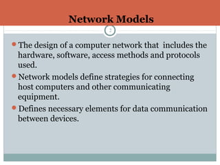
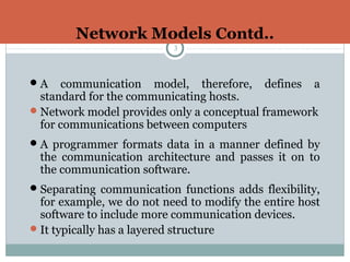
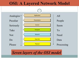
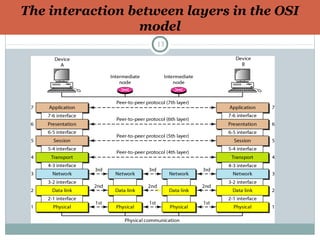
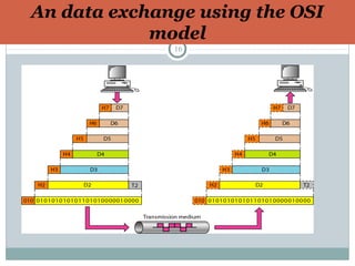
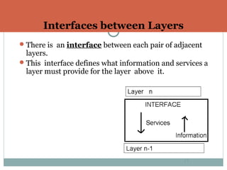
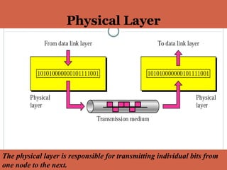
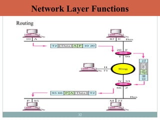
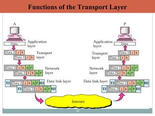
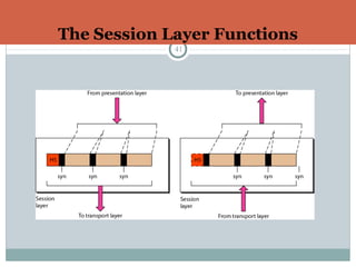
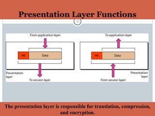
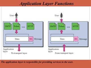
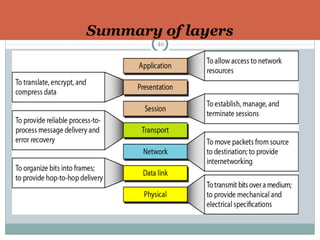
1
Computer Networks
OSI-ISO Model
Chandrakant Mallick
Network Models
2
ď‚—The design of a computer network that includes the
hardware, software, access methods and protocols
used.
ď‚—Network models define strategies for connecting
host computers and other communicating
equipment.
ď‚—Defines necessary elements for data communication
between devices.
Network Models Contd..
3
ď‚—A communication model, therefore, defines a
standard for the communicating hosts.
ď‚—Network model provides only a conceptual framework
for communications between computers
ď‚—A programmer formats data in a manner defined by
the communication architecture and passes it on to
the communication software.
ď‚—Separating communication functions adds flexibility,
for example, we do not need to modify the entire host
software to include more communication devices.
ď‚—It typically has a layered structure
Examples of Networks Architecture
4
Example of a Home Networks
5
Layered Architecture – Scenario 1
6
7
Layered Architecture – Scenario 2
(The philosopher-translator-secretary architecture)
Benefits of Layered Architecture
8
ď‚—Layer architecture simplifies the network design.
ď‚—It is easy to debug network applications in a layered
architecture network.
ď‚—The network management is easier due to the layered
architecture.
ď‚—Network layers follow a set of rules, called protocol.
ď‚—The protocol defines the format of the data being
exchanged, and the control and timing for the handshake
between layers.
Open Systems Interconnection
(OSI) Model9
ď‚—International standard organization (ISO) established a
committee in 1977 to develop an architecture for
computer communication.
ď‚—Open Systems Interconnection (OSI) reference model is
the result of this effort.
ď‚—In 1984, the Open Systems Interconnection (OSI)
reference model was approved as an international
standard for communications architecture.
Term “open” denotes the ability to connect any two
systems which conform to the reference model and
associated standards.
Open Systems Interconnection
(OSI) Model contd..10
ď‚—An ISO (International Standard Organization) that
covers all aspects of network communications is the
Open System Interconnection (OSI) model.
ď‚—An open system is a model that allows any two different
systems to communicate regardless of their underlying
architecture (hardware or software).
ď‚—The OSI model is not a protocol; it is model for
understanding and designing a network architecture that
is flexible, robust and interoperable.
Open Systems Interconnection (OSI)
Model contd..11
ď‚—The OSI model is now considered the primary Architectural
model for inter-computer communications.
ď‚—The OSI model describes how information or data makes its
way from application programmes (such as spreadsheets)
through a network medium (such as wire) to another
application programme located on another network.
ď‚—The OSI reference model divides the problem of moving
information between computers over a network medium
into SEVEN smaller and more manageable problems .
ď‚—This separation into smaller more manageable functions is
known as layering.
12
OSI: A Layered Network Model
Analogies
Peculiar
Seriously
Take
Not
Do
Please
All
People
Seem
To
Need
Data
Processing
Seven layers of the OSI model
The interaction between layers in the OSI
model
13
A Layered Architecture of OSI Model
14
ď‚—The process of breaking up the functions or tasks of
networking into layers reduces complexity.
ď‚—Each layer provides a service to the layer above it in the
protocol specification.
 Each layer communicates with the same layer’s software or
hardware on other computers.
ď‚—The lower 4 layers (transport, network, data link and physical
—Layers 4, 3, 2, and 1) are concerned with the flow of data
from end to end through the network.
ď‚—The upper four layers of the OSI model (application,
presentation and session—Layers 7, 6 and 5) are orientated
more toward services to the applications.
ď‚—Data is Encapsulated with the necessary protocol information
as it moves down the layers before network transit.
Peer-to-Peer Process
15
ď‚—Within a single machine, each layer calls upon
services of the layer just below it.
ď‚—Layer 3, for example, uses the services provided by
layer 2 and provides services for layer 4.
ď‚—Between machines, layer x on one machine
communicates with layer x on another machine, by
using a protocol (this is Peer-to-Peer Process).
ď‚—Communication between machines is therefore a
peer-to-peer process using protocols appropriate to a
given layer.
An data exchange using the OSI
model
16
Interfaces between Layers
ď‚—There is an interface between each pair of adjacent
layers.
ď‚—This interface defines what information and services a
layer must provide for the layer above it.
17
Physical Layer
18
ď‚—The physical layer coordinates the
functions required to transmit a bit
stream over a physical medium.
ď‚—It also defines the procedures and
functions that physical devices and
interfaces have to perform for
transmission occur.
Physical Layer
19
The physical layer is responsible for transmitting individual bits from
one node to the next.
Physical Layer
20
The physical layer is concerned with the following:
ď‚— Physical characteristics of interfaces and
media: The physical layer defines the
characteristics of the interface between devices and
the transmission media, including its type.
ď‚— Representation of the bits: the physical layer
data consist of a stream of bits without any
interpretation. To be transmitted, bits must be
encoded into signals –electrical or optical-. The
physical layer defines the type of encoding.
ď‚— Data rate: The physical layer defines the
transmission rate, the number of bits sent each
second.
Physical Layer
21
ď‚— Line configuration: the physical layer is
concerned with the connection of devices to the
medium.
ď‚— Physical topology: The Physical layer is
responsible for defining the physical layout called
topology of the underlying network such as
star,ring,bus,mesh and tree topology.
ď‚— Transmission Mode: The physical layer is also
responsible for defining the transmission mode
such as simplex, half-duplex, full-duplex mode.
Data Link Layer
22
ď‚—The data link layer transforms the raw data
streams of the physical layer to data frames to be
transmitted over a reliable link and is
responsible for error free node-to-node delivery
of data.
ď‚—It makes the physical layer appear error free to
the upper layer (network layer).
Data Link Layer
23
The data link layer is responsible for transmitting frames from one
node to the next.
24
Node-to-node delivery
25
ď‚— Framing. The data link layer divides the stream of
bits received from the network layer into data units
called frames.
ď‚— Physical addressing. If frames are to be
distributed to different systems on the network, the
data link layer adds a header to the frame to define
the physical address of the sender (source address)
and/or receiver (destination address) of the frame.
ď‚— If the frame is intended for a system outside the
sender’s network, the receiver address is the
address of the device that connects one network to
the next.
Functions of the data link layer:
26
Functions of the data link layer:
27
ď‚—Flow Control. If the rate at which the data are
absorbed by the receiver is less than the rate produced in
the sender, the data link layer imposes a flow control
mechanism to prevent overwhelming the receiver.
ď‚—Error control. The data link layer adds reliability to
the physical layer by adding mechanisms to detect and
retransmit damaged or lost frames. Error control is
normally achieved through a trailer to the end of the
frame.
ď‚—Access Control. When two or more devices are
connected to the same link, data link layer protocols are
necessary to determine which device has control over the
link at any time.
Functions of the data link layer:
Network Layer
28
ď‚§The Network layer is responsible for the source-to-destination
delivery of a packet possible across multiple networks.
ď‚§If two systems are connected to the same link, there is usually no
need for a network layer. However, if the two systems are
attached to different networks, there is often a need for the
network layer to accomplish source-to-destination delivery.
Network Layer Functions
29
The network layer is responsible for the delivery of packets from the
original source to the final destination.
30
Source-to-destination delivery
Network Layer Functions
31
ď‚—The typical functionalities of network layer are:
ď‚—Logical addressing. The physical addressing
implemented by the data link layer handles the addressing
problem locally.
ď‚—The network layer adds a header to the packet coming
from the upper layer, among other things, includes the
logical address of the sender and receiver.
ď‚—Routing. When independent networks or links are
connected together to create an internetwork (a
network of networks) or a large network, the connecting
devices (called routers or gateways) route or switch the
packets to their final destination.
ď‚—It uses the Internet Protocol (IP) for internetworking and
routing
32
Network Layer Functions
Routing
Transport Layer
33
ď‚—The transport layer is responsible for process-to-process
delivery of the entire message.
ď‚—The network layer oversees host-to-destination delivery of
individual packets, it does not recognize any relationship
between those packets.
ď‚—The transport layer ensures that the whole message arrives
intact and in order, overseeing both error control and flow
control at the process-to-process level.
34
The transport layer is responsible for delivery of a message from one
process to another.
Transport Layer
35
Reliable process-to-process delivery of a message
Functions of the Transport Layer
36
The Specific functions of the transport Layer include:
ď‚—Port addressing: computer often run several processes
(running programs) at the same time. Process-to-process
delivery means delivery from a specific process on one
computer to a specific process on the other.
ď‚—The transport layer header include a type of address called
port address.
ď‚—The network layer gets each packet to the correct
computer; the transport layer gets the entire message to
the correct process on that computer.
ď‚—Segmentation and Reassembly: a message is divided
into transmittable segments, each having a sequence
number. These numbers enable the transport layer to
reassemble the message correctly upon arrival at the
destination.
Functions of the Transport Layer
37
ď‚—Connection control: The transport layer can be
either connectionless or connection-oriented.
ď‚—A connectionless transport layer treats each segment
as an independent packet and delivers it to the
transport layer at the destination machine.
ď‚—A connection-oriented transport layer makes a
connection with the transport layer at the destination
machine first before delivering the packets. After all the
data are transferred, the connection is terminated.
Functions of the Transport Layer
38
ď‚—Flow control: the transport layer performs a flow
control end to end. The data link layer performs flow
control across a single link.
ď‚—Error control: the transport layer performs error
control end to end. The data link layer performs
control across a single link.
ď‚—Efficiency: It ensures efficient delivery of the data
packets over the network to the correct process.
39
Functions of the Transport Layer
40
ď‚—The session layer allows two application on separate
computers to set up use and terminate a connection
called a session.
ď‚—The session layer is the network dialog controller.
ď‚—It establishes, maintains, and synchronizes the
interaction between communicating devices.
The specific functions of the session layer are:
ď‚—Dialog control: Allows communication either in half-
duplex or full-duplex mode.
ď‚—Synchronization: Adds check points to the stream of
data for acknowledgement and synchronization
between sender and the receiver.
The Session Layer
The session layer is responsible for dialog
control and synchronization.
The Session Layer Functions
41
Presentation Layer
42
ď‚—The presentation layer is concerned with
syntax and semantics of the information
exchanged between the two systems.
ď‚—It carries out the functions like
 Protocol conversion
 Data translation
 Encryption and decryption
 Compression and decompression.
Presentation Layer Functions
43
The presentation layer is responsible for translation, compression,
and encryption.
Application Layer
44
ď‚—The application layer enables the user to access
the network services.
ď‚—It provides user interfaces and support for services
such as
 Electronic email
 Remote login using TELNET
 File transfer through FTP
 Web services through WWW and so on.
45
Application Layer Functions
The application layer is responsible for providing services to the user.
Summary of layers
46

OSI Network Reference Model

  • 1.
  • 2.
    Network Models 2 ď‚—The designof a computer network that includes the hardware, software, access methods and protocols used. ď‚—Network models define strategies for connecting host computers and other communicating equipment. ď‚—Defines necessary elements for data communication between devices.
  • 3.
    Network Models Contd.. 3 ď‚—Acommunication model, therefore, defines a standard for the communicating hosts. ď‚—Network model provides only a conceptual framework for communications between computers ď‚—A programmer formats data in a manner defined by the communication architecture and passes it on to the communication software. ď‚—Separating communication functions adds flexibility, for example, we do not need to modify the entire host software to include more communication devices. ď‚—It typically has a layered structure
  • 4.
    Examples of NetworksArchitecture 4
  • 5.
    Example of aHome Networks 5
  • 6.
  • 7.
    7 Layered Architecture –Scenario 2 (The philosopher-translator-secretary architecture)
  • 8.
    Benefits of LayeredArchitecture 8 ď‚—Layer architecture simplifies the network design. ď‚—It is easy to debug network applications in a layered architecture network. ď‚—The network management is easier due to the layered architecture. ď‚—Network layers follow a set of rules, called protocol. ď‚—The protocol defines the format of the data being exchanged, and the control and timing for the handshake between layers.
  • 9.
    Open Systems Interconnection (OSI)Model9 International standard organization (ISO) established a committee in 1977 to develop an architecture for computer communication. Open Systems Interconnection (OSI) reference model is the result of this effort. In 1984, the Open Systems Interconnection (OSI) reference model was approved as an international standard for communications architecture. Term “open” denotes the ability to connect any two systems which conform to the reference model and associated standards.
  • 10.
    Open Systems Interconnection (OSI)Model contd..10 ď‚—An ISO (International Standard Organization) that covers all aspects of network communications is the Open System Interconnection (OSI) model. ď‚—An open system is a model that allows any two different systems to communicate regardless of their underlying architecture (hardware or software). ď‚—The OSI model is not a protocol; it is model for understanding and designing a network architecture that is flexible, robust and interoperable.
  • 11.
    Open Systems Interconnection(OSI) Model contd..11 ď‚—The OSI model is now considered the primary Architectural model for inter-computer communications. ď‚—The OSI model describes how information or data makes its way from application programmes (such as spreadsheets) through a network medium (such as wire) to another application programme located on another network. ď‚—The OSI reference model divides the problem of moving information between computers over a network medium into SEVEN smaller and more manageable problems . ď‚—This separation into smaller more manageable functions is known as layering.
  • 12.
    12 OSI: A LayeredNetwork Model Analogies Peculiar Seriously Take Not Do Please All People Seem To Need Data Processing Seven layers of the OSI model
  • 13.
    The interaction betweenlayers in the OSI model 13
  • 14.
    A Layered Architectureof OSI Model 14 The process of breaking up the functions or tasks of networking into layers reduces complexity. Each layer provides a service to the layer above it in the protocol specification.  Each layer communicates with the same layer’s software or hardware on other computers. The lower 4 layers (transport, network, data link and physical —Layers 4, 3, 2, and 1) are concerned with the flow of data from end to end through the network. The upper four layers of the OSI model (application, presentation and session—Layers 7, 6 and 5) are orientated more toward services to the applications. Data is Encapsulated with the necessary protocol information as it moves down the layers before network transit.
  • 15.
    Peer-to-Peer Process 15 ď‚—Within asingle machine, each layer calls upon services of the layer just below it. ď‚—Layer 3, for example, uses the services provided by layer 2 and provides services for layer 4. ď‚—Between machines, layer x on one machine communicates with layer x on another machine, by using a protocol (this is Peer-to-Peer Process). ď‚—Communication between machines is therefore a peer-to-peer process using protocols appropriate to a given layer.
  • 16.
    An data exchangeusing the OSI model 16
  • 17.
    Interfaces between Layers ď‚—Thereis an interface between each pair of adjacent layers. ď‚—This interface defines what information and services a layer must provide for the layer above it. 17
  • 18.
    Physical Layer 18 ď‚—The physicallayer coordinates the functions required to transmit a bit stream over a physical medium. ď‚—It also defines the procedures and functions that physical devices and interfaces have to perform for transmission occur.
  • 19.
    Physical Layer 19 The physicallayer is responsible for transmitting individual bits from one node to the next.
  • 20.
    Physical Layer 20 The physicallayer is concerned with the following:  Physical characteristics of interfaces and media: The physical layer defines the characteristics of the interface between devices and the transmission media, including its type.  Representation of the bits: the physical layer data consist of a stream of bits without any interpretation. To be transmitted, bits must be encoded into signals –electrical or optical-. The physical layer defines the type of encoding.  Data rate: The physical layer defines the transmission rate, the number of bits sent each second.
  • 21.
    Physical Layer 21 ď‚— Lineconfiguration: the physical layer is concerned with the connection of devices to the medium. ď‚— Physical topology: The Physical layer is responsible for defining the physical layout called topology of the underlying network such as star,ring,bus,mesh and tree topology. ď‚— Transmission Mode: The physical layer is also responsible for defining the transmission mode such as simplex, half-duplex, full-duplex mode.
  • 22.
    Data Link Layer 22 ď‚—Thedata link layer transforms the raw data streams of the physical layer to data frames to be transmitted over a reliable link and is responsible for error free node-to-node delivery of data. ď‚—It makes the physical layer appear error free to the upper layer (network layer).
  • 23.
    Data Link Layer 23 Thedata link layer is responsible for transmitting frames from one node to the next.
  • 24.
  • 25.
    25  Framing. Thedata link layer divides the stream of bits received from the network layer into data units called frames.  Physical addressing. If frames are to be distributed to different systems on the network, the data link layer adds a header to the frame to define the physical address of the sender (source address) and/or receiver (destination address) of the frame.  If the frame is intended for a system outside the sender’s network, the receiver address is the address of the device that connects one network to the next. Functions of the data link layer:
  • 26.
    26 Functions of thedata link layer:
  • 27.
    27 ď‚—Flow Control. Ifthe rate at which the data are absorbed by the receiver is less than the rate produced in the sender, the data link layer imposes a flow control mechanism to prevent overwhelming the receiver. ď‚—Error control. The data link layer adds reliability to the physical layer by adding mechanisms to detect and retransmit damaged or lost frames. Error control is normally achieved through a trailer to the end of the frame. ď‚—Access Control. When two or more devices are connected to the same link, data link layer protocols are necessary to determine which device has control over the link at any time. Functions of the data link layer:
  • 28.
    Network Layer 28 ď‚§The Networklayer is responsible for the source-to-destination delivery of a packet possible across multiple networks. ď‚§If two systems are connected to the same link, there is usually no need for a network layer. However, if the two systems are attached to different networks, there is often a need for the network layer to accomplish source-to-destination delivery.
  • 29.
    Network Layer Functions 29 Thenetwork layer is responsible for the delivery of packets from the original source to the final destination.
  • 30.
  • 31.
    Network Layer Functions 31 ď‚—Thetypical functionalities of network layer are: ď‚—Logical addressing. The physical addressing implemented by the data link layer handles the addressing problem locally. ď‚—The network layer adds a header to the packet coming from the upper layer, among other things, includes the logical address of the sender and receiver. ď‚—Routing. When independent networks or links are connected together to create an internetwork (a network of networks) or a large network, the connecting devices (called routers or gateways) route or switch the packets to their final destination. ď‚—It uses the Internet Protocol (IP) for internetworking and routing
  • 32.
  • 33.
    Transport Layer 33 ď‚—The transportlayer is responsible for process-to-process delivery of the entire message. ď‚—The network layer oversees host-to-destination delivery of individual packets, it does not recognize any relationship between those packets. ď‚—The transport layer ensures that the whole message arrives intact and in order, overseeing both error control and flow control at the process-to-process level.
  • 34.
    34 The transport layeris responsible for delivery of a message from one process to another. Transport Layer
  • 35.
  • 36.
    Functions of theTransport Layer 36 The Specific functions of the transport Layer include: ď‚—Port addressing: computer often run several processes (running programs) at the same time. Process-to-process delivery means delivery from a specific process on one computer to a specific process on the other. ď‚—The transport layer header include a type of address called port address. ď‚—The network layer gets each packet to the correct computer; the transport layer gets the entire message to the correct process on that computer. ď‚—Segmentation and Reassembly: a message is divided into transmittable segments, each having a sequence number. These numbers enable the transport layer to reassemble the message correctly upon arrival at the destination.
  • 37.
    Functions of theTransport Layer 37 ď‚—Connection control: The transport layer can be either connectionless or connection-oriented. ď‚—A connectionless transport layer treats each segment as an independent packet and delivers it to the transport layer at the destination machine. ď‚—A connection-oriented transport layer makes a connection with the transport layer at the destination machine first before delivering the packets. After all the data are transferred, the connection is terminated.
  • 38.
    Functions of theTransport Layer 38 ď‚—Flow control: the transport layer performs a flow control end to end. The data link layer performs flow control across a single link. ď‚—Error control: the transport layer performs error control end to end. The data link layer performs control across a single link. ď‚—Efficiency: It ensures efficient delivery of the data packets over the network to the correct process.
  • 39.
    39 Functions of theTransport Layer
  • 40.
    40 ď‚—The session layerallows two application on separate computers to set up use and terminate a connection called a session. ď‚—The session layer is the network dialog controller. ď‚—It establishes, maintains, and synchronizes the interaction between communicating devices. The specific functions of the session layer are: ď‚—Dialog control: Allows communication either in half- duplex or full-duplex mode. ď‚—Synchronization: Adds check points to the stream of data for acknowledgement and synchronization between sender and the receiver. The Session Layer The session layer is responsible for dialog control and synchronization.
  • 41.
    The Session LayerFunctions 41
  • 42.
    Presentation Layer 42 The presentationlayer is concerned with syntax and semantics of the information exchanged between the two systems. It carries out the functions like  Protocol conversion  Data translation  Encryption and decryption  Compression and decompression.
  • 43.
    Presentation Layer Functions 43 Thepresentation layer is responsible for translation, compression, and encryption.
  • 44.
    Application Layer 44 The applicationlayer enables the user to access the network services. It provides user interfaces and support for services such as  Electronic email  Remote login using TELNET  File transfer through FTP  Web services through WWW and so on.
  • 45.
    45 Application Layer Functions Theapplication layer is responsible for providing services to the user.
  • 46.