Download as PDF, PPTX
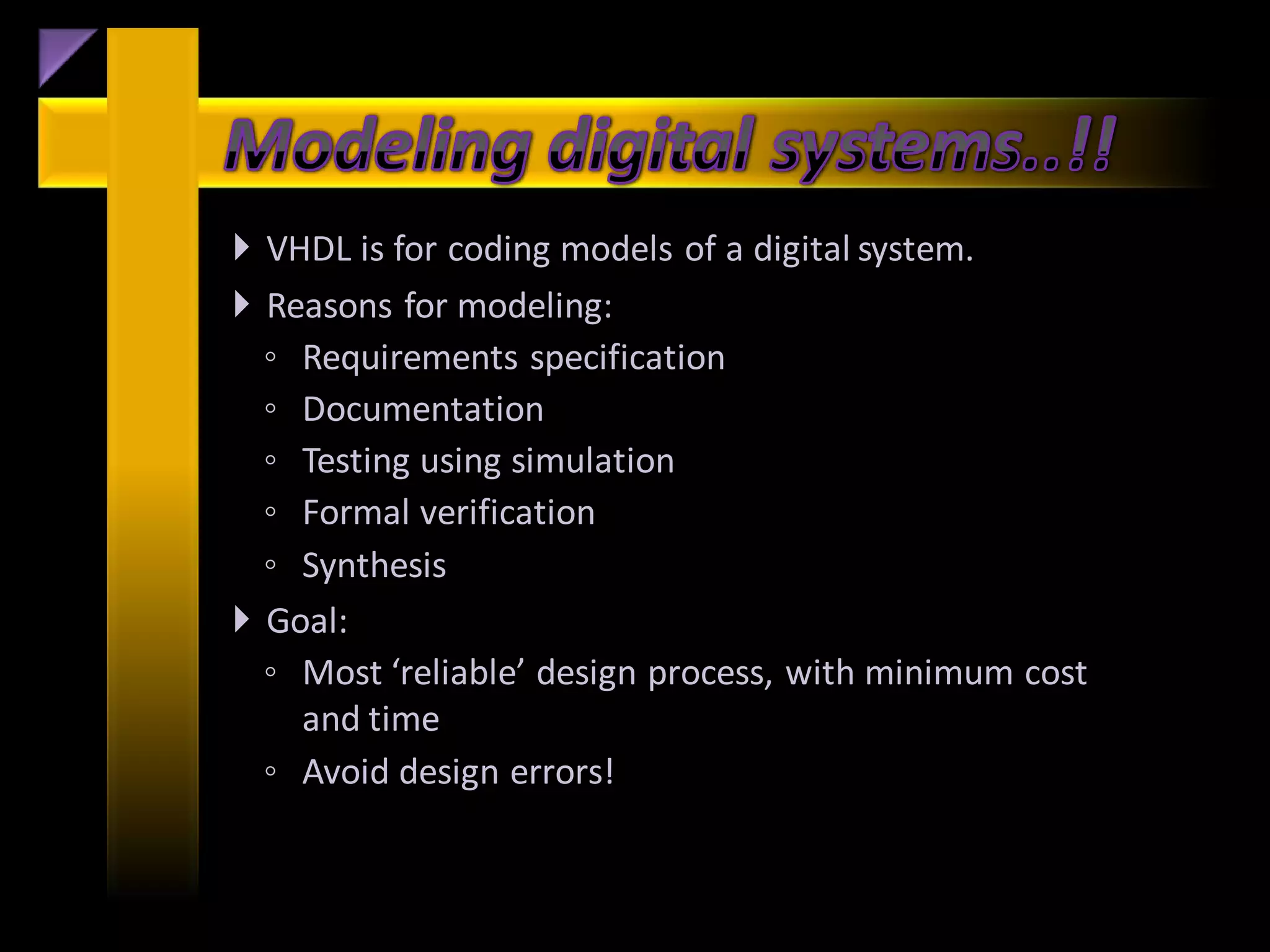
![• Implement the VHDL portion of coding for synthesis.
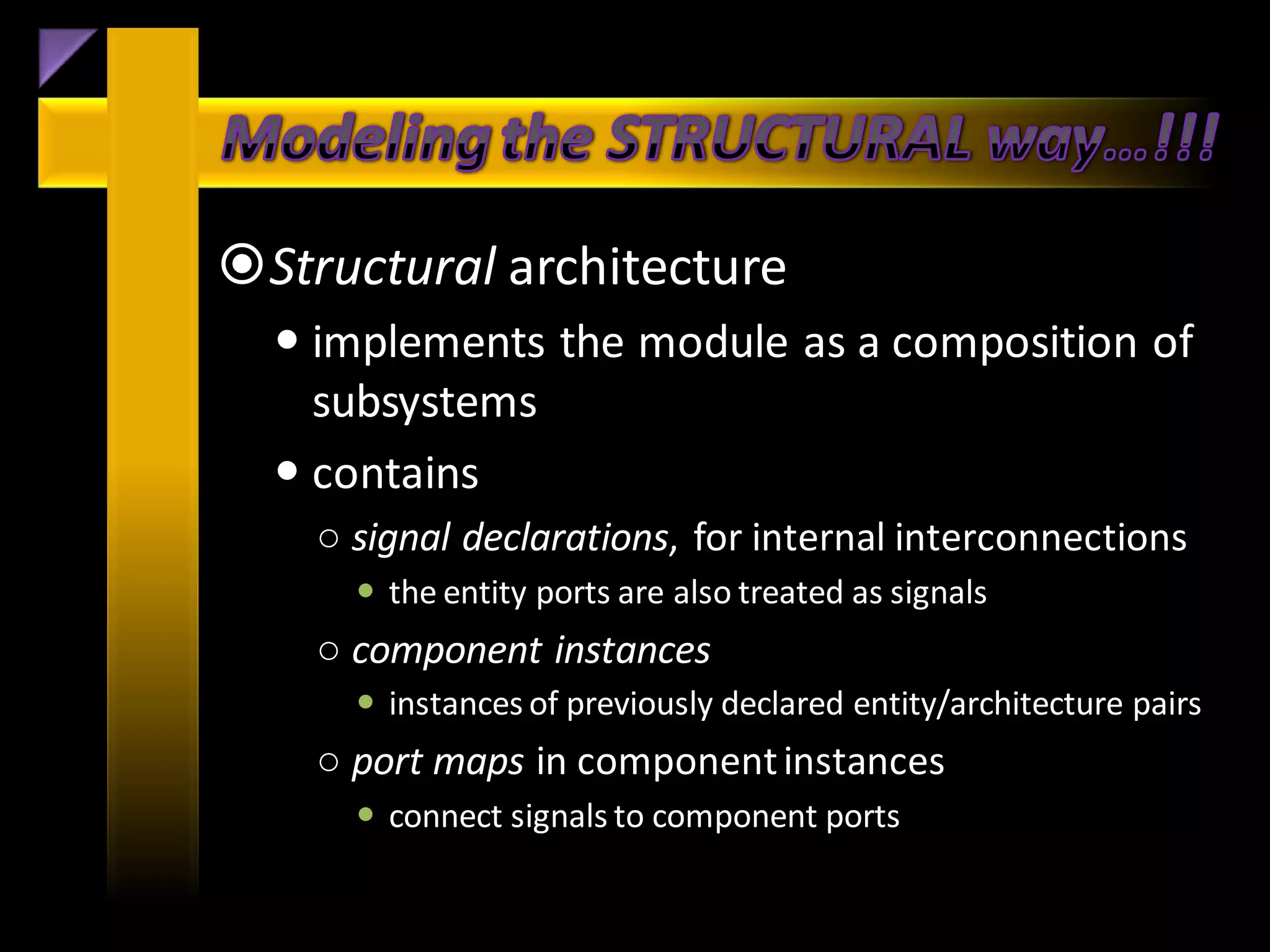
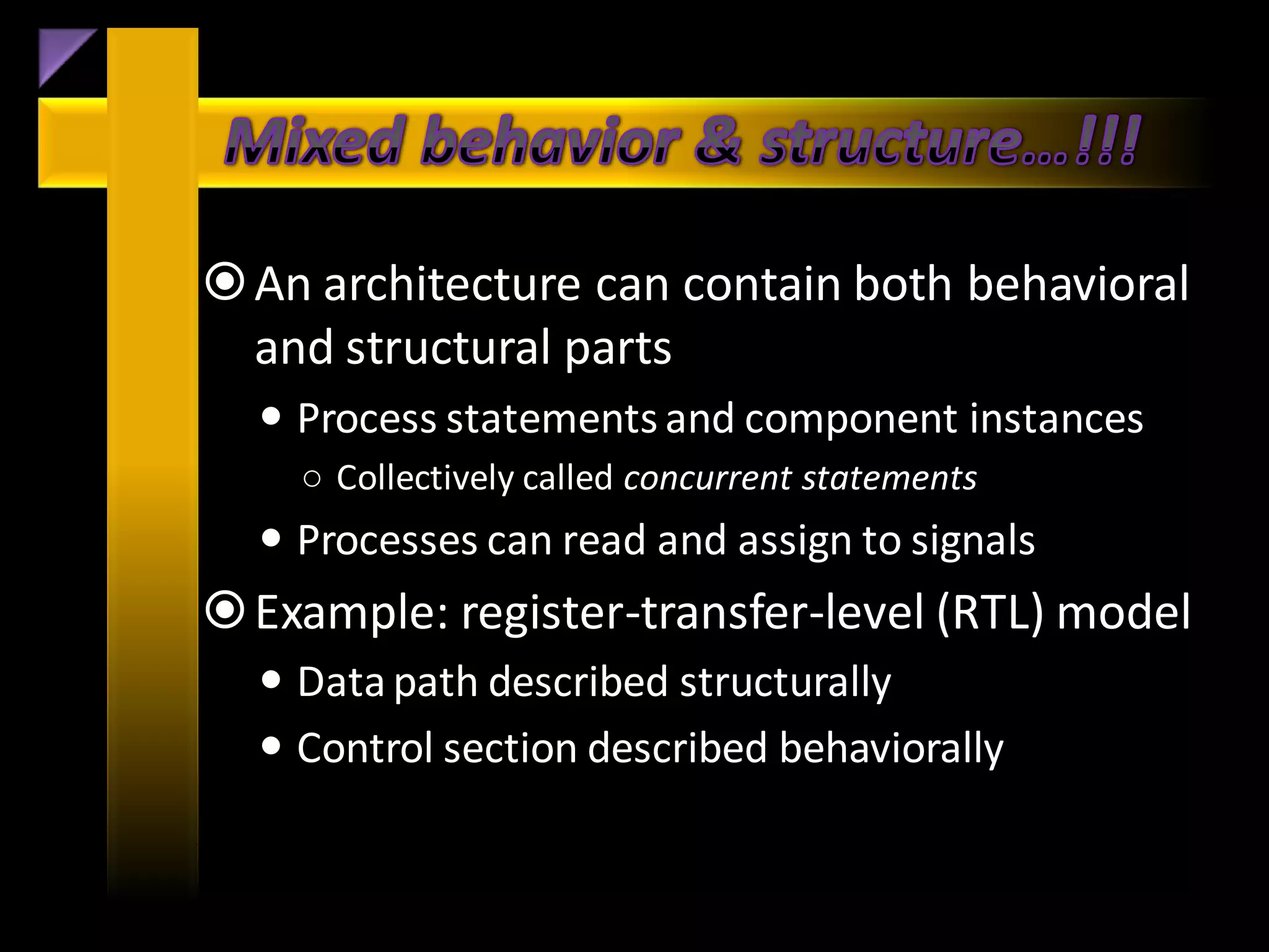
• Identify the differences between behavioral and
structural coding styles.
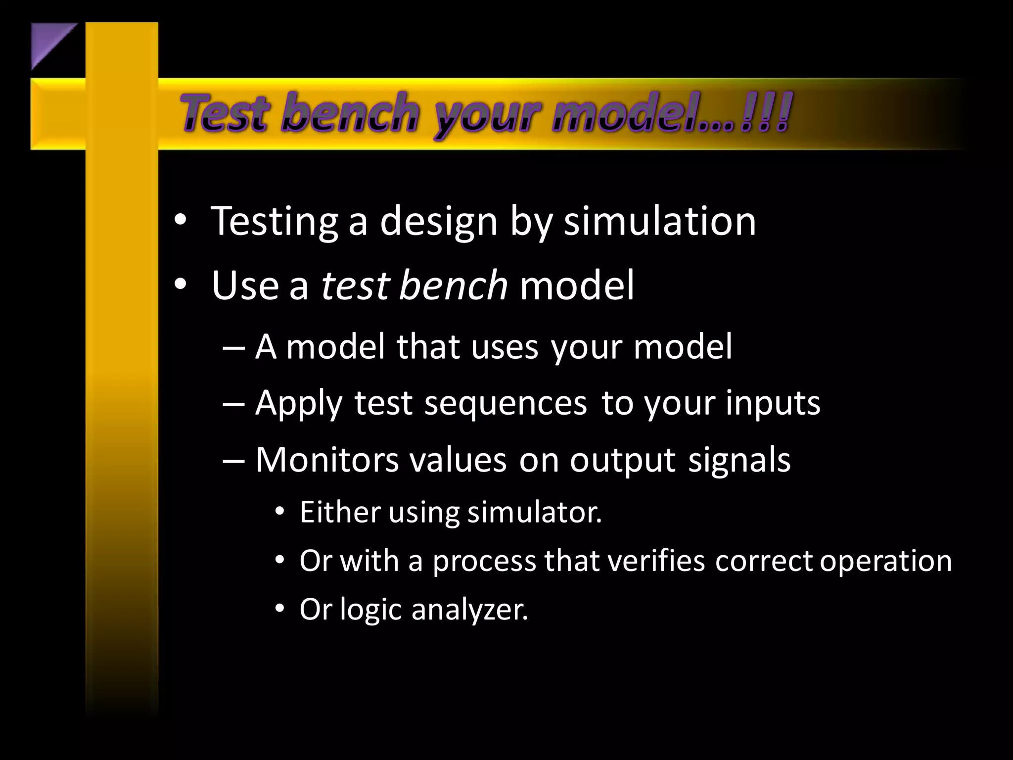
• Distinguish coding for synthesis versus coding for
simulation.
• Use scalar and composite data types to represent
information.
• Use concurrent and sequential control structure to
regulate information flow.
• Implement common VHDL constructs (Finite State
Machines [FSMs], RAM/ROM data structures).](https://image.slidesharecdn.com/summertrainingvhdl-130226011008-phpapp02/75/Summer-training-vhdl-21-2048.jpg)

A seminar on VLSI design (VHDL) is being organized to enhance the skills of aspiring engineers, with an emphasis on modeling digital systems using VHDL. The document outlines the goals of VHDL, its advantages over other programming languages, and various architectural concepts involved in modeling. It also highlights best practices for testing designs and emphasizes the importance of efficient design processes in electronics engineering.