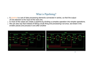
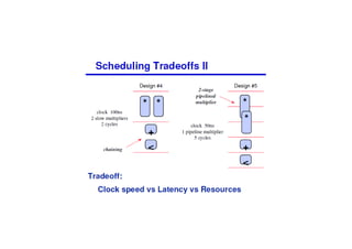
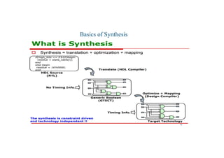
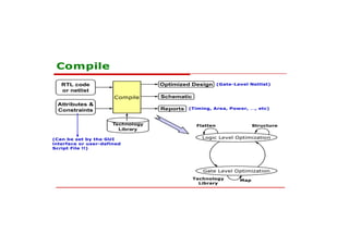
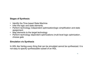
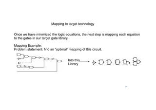
This document discusses the basics of RTL design and synthesis. It covers stages of synthesis including identifying state machines, inferring logic and state elements, optimization, and mapping to target technology. It notes that not everything that can be simulated can be synthesized. Good coding style reduces hazards and improves optimization. Examples are given of how logic, sequential logic, and datapaths can be synthesized. Pipelining is discussed as dividing complex operations into simpler operations processed sequentially.

![17
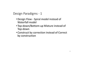
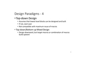
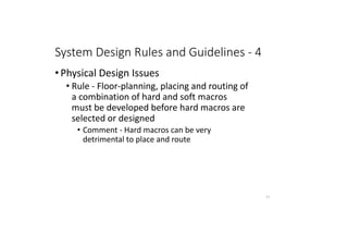
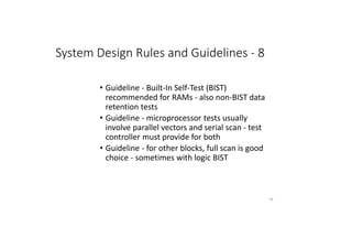
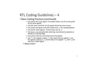
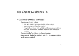
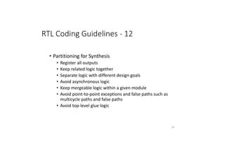
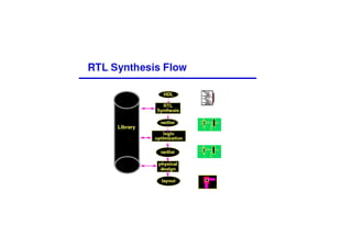
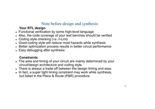
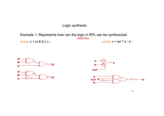
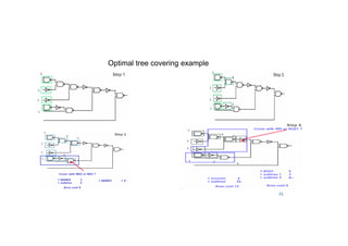
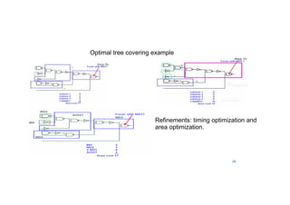
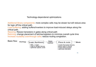
Logic synthesis
Example 2: Represents how can the logic in RTL can be synthesized.
wire [3:0] x,y,sum;
wire cout;
assign {cout,sum} = x + y;](https://image.slidesharecdn.com/24-02-18rejenderpratap-220829154408-3c27d9bf/85/24-02-18-Rejender-pratap-pdf-17-320.jpg)
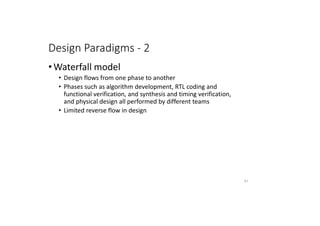
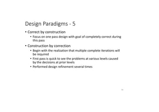
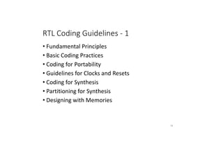
![18
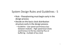
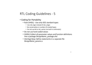
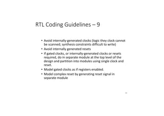
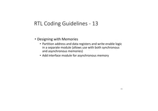
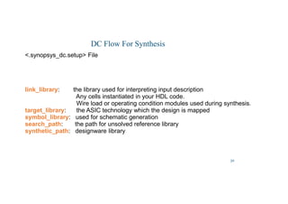
Example 3: Represents how can the logic in RTL can be synthesized.
module parity (in,p);
parameter WIDTH = 2; // default width is 2
input [WIDTH-1 : 0] in;
output p;
//simple approach : assign p = ^in;
//here is another , more general approach
reg p;
always @(in) begin: loop
integer i;
reg parity = 0;
for (i = 0; I WIDTH; i = i + 1)
parity = parity ^ in[ i ] ;
p = parity;
end
endmodule
wire [3:0] word;
wire parity;
parity #(4) ecc (word,parity) //specify WIDTH = 4
Logic synthesis](https://image.slidesharecdn.com/24-02-18rejenderpratap-220829154408-3c27d9bf/85/24-02-18-Rejender-pratap-pdf-18-320.jpg)
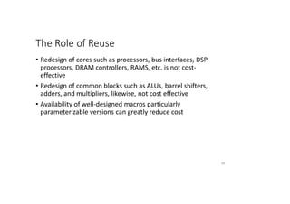
![38
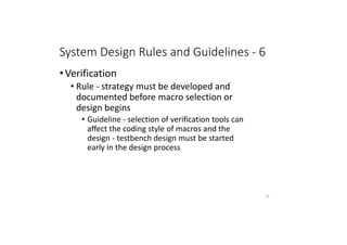
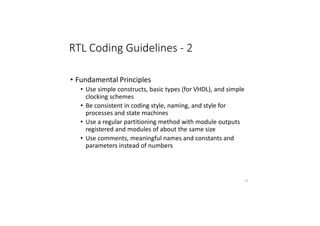
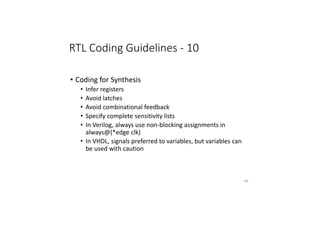
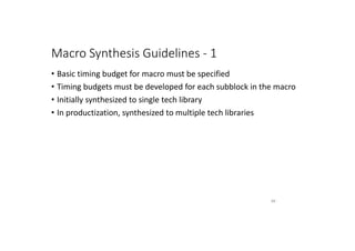
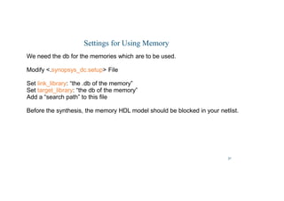
Magnet Placement
• The tool will only perform magnet placement if the standard cells are placed. If you use the
magnet_placement command before the standard cells are placed, the tool will not pull any
objects to the specified magnet. The tool will issue a warning for this condition.
• To perform magnet placement, use the magnet_placement command with a specification of
the magnets and options for any special functions you need to perform:
dc_shell-topo magnet_placement [options] magnet_objects
• To specify the fanout limit, use the magnet_placement_fanout_limit variable. If the
fanout of a net exceeds the specified limit, the command does not pull
cells of the net toward the magnet objects. The default magnet_placement lt setting is 1000.
• Magnet placement allows cells to overlap by default. To prevent overlapping of cells, set the
magnet_placement_disable_overlap variable to true.
• To return a collection of cells that can be moved with magnet placement, use the
get_magnet_cells command with the options you need:
dc_shell-topo get_magnet_cells [options] magnet_list](https://image.slidesharecdn.com/24-02-18rejenderpratap-220829154408-3c27d9bf/85/24-02-18-Rejender-pratap-pdf-38-320.jpg)

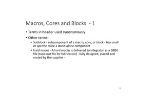
![46
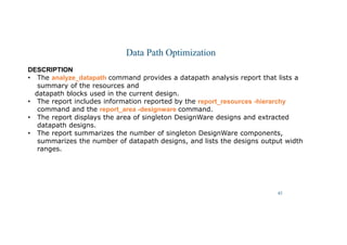
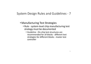
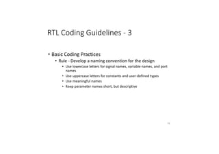
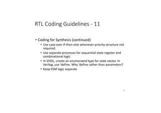
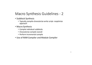
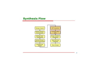
Data Path Optimization
analyze_datapath
Provides a datapath analysis report that lists the resources and datapath blocks used in the
current design.
SYNTAX
analyze_datapath
[-file file_name]
ARGUMENTS
-file file_name
Specifies the file name of a log file that contains the report _resources -hierarchy and report
_area -designware reports from a previously compiled design. This option enables you start the
tool and use the analyze_datapath command to generate a datapath analysis report for a
design without having to read in and compile the design a second time.](https://image.slidesharecdn.com/24-02-18rejenderpratap-220829154408-3c27d9bf/85/24-02-18-Rejender-pratap-pdf-46-320.jpg)