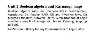
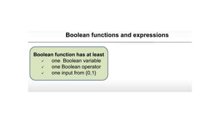
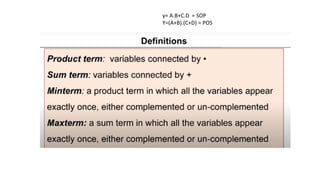
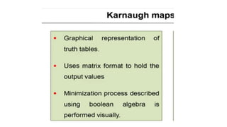
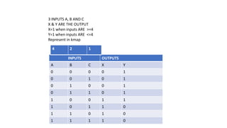
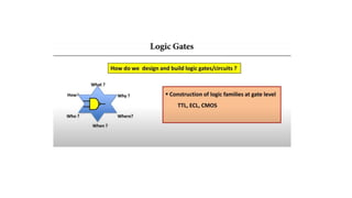
The document provides information about Unit 2 of a course which includes:
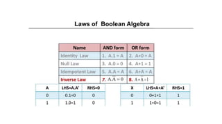
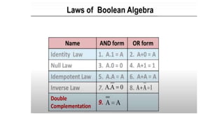
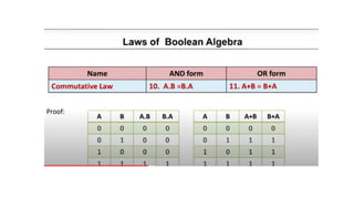
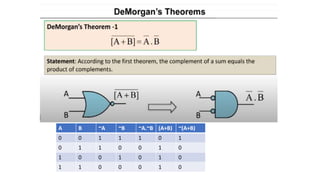
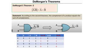
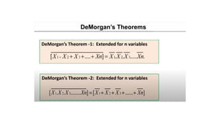
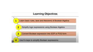
- Boolean algebra rules and laws such as commutative, associative, distributive for AND, OR and inversion. De Morgan's theorem.
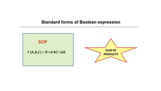
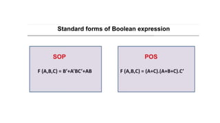
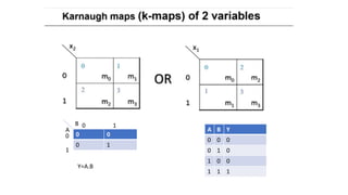
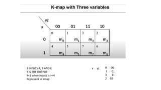
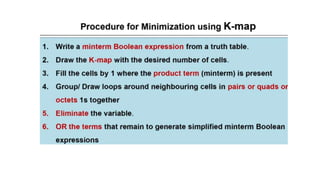
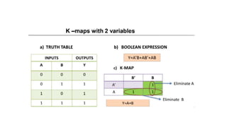
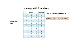
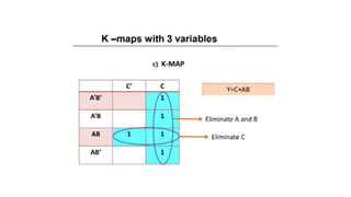
- Simplifying logic equations using Boolean algebra rules and Karnaugh maps up to 4 bits.
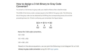
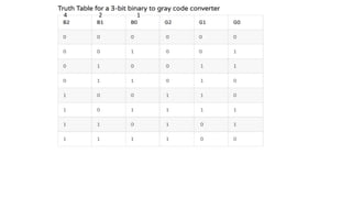
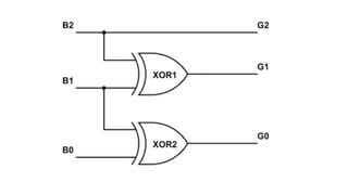
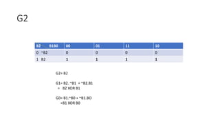
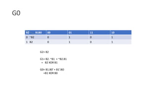
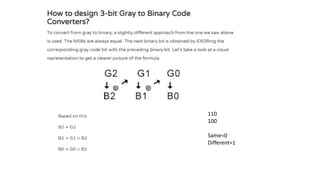
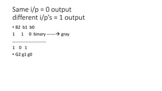
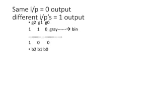
- Converting between binary and gray codes.
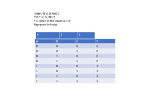
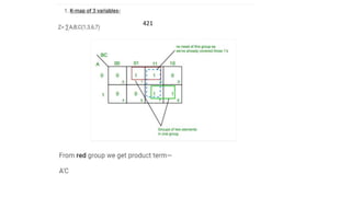
- Minimizing logic expressions using Karnaugh maps.


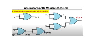


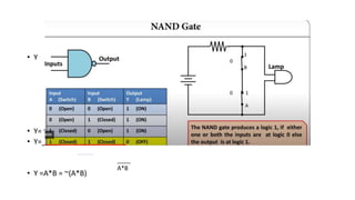

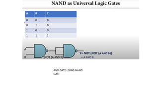
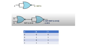
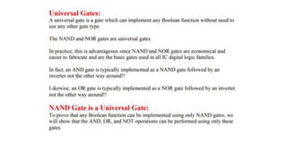
![• Y= NOT[(NOT A).(NOT B)]
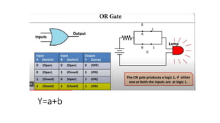
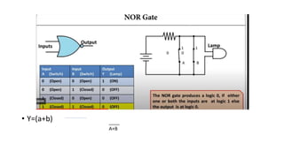
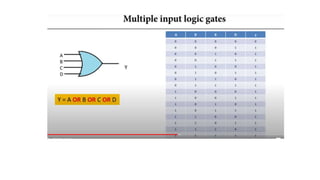
• Y=A+B
OR GATE
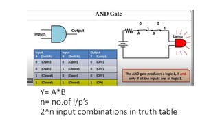
A B Y
0 0 .0
0 1 1
1 0 1
1 1 1
OR GATE USING NAND GATE](https://image.slidesharecdn.com/hz5t12k9sneawkbn18id-unit-2-boolean-algebra-and-karnaugh-maps-240208132606-3b959371/85/Unit_2_Boolean_algebra_and_Karnaugh_maps-pptx-73-320.jpg)


![[DSC Europe 25] Bojan Djuricic - Predictive Design Process.pdf](https://cdn.slidesharecdn.com/ss_thumbnails/5awdrbedqdek3gqu2ezy-4-the-predictive-design-bojan-djuricic-260120105856-6c399e9b-thumbnail.jpg?width=640&height=640&fit=bounds)

![[DSC Europe 25] Elena Menshikova - AI-Powered Operational Excellence: Revolut...](https://cdn.slidesharecdn.com/ss_thumbnails/es6nholbqy3zaao2c2yd-2-elena-menshikova-data-ai-in-decision-making-260115093812-4fba8b38-thumbnail.jpg?width=640&height=640&fit=bounds)


![[DSC Europe 25] Andrzej Kowalczyk - AI - how to start small and grow in the f...](https://cdn.slidesharecdn.com/ss_thumbnails/oy1zmo94qv6vpcqjvno2-andrzej-kowalczyk-ai-how-to-start-small-and-grow-in-the-future-1-260119121559-cf093b23-thumbnail.jpg?width=640&height=640&fit=bounds)


