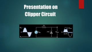
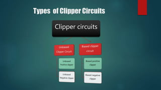
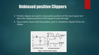
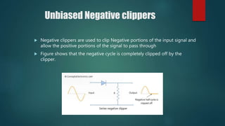
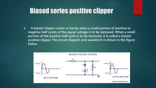
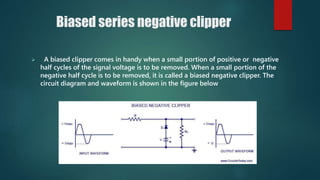
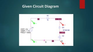
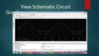
Bangladesh Army University
of Engineering & Technology
PRESENTED BY
MD. MAHBUB HASAN
ID: 151012
Department: EEE
Presentation on
Clipper Circuit
Outline
 Clipper Circuit.
 Types Of Clippers Circuits.
 Unbiased Positive Clipper Circuit.
 Unbiased Negative Clipper Circuit.
 Biased Positive Clipper Circuit.
 Biased Negative Clipper Circuit.
 Observing Input & Output signal Using Pspice.
 Given Circuit Diagram
 View Schematic Circuit Graph.
 Simulation Process from Video Capture.
Clipper
Circuit
 In electronics, a clipper is a device designed to
prevent the output of a circuit from exceeding a
predetermined voltage level without distorting the
remaining part of the applied waveform.
 Clipping circuits are also called slicers, amplitude
selectors or limiters.
Types of Clipper Circuits
Clipper circuits
Unbiased positive Clippers
 Positive clippers are used to clip positive portions of the input signal and
allow the negative portions of the signal to pass through.
 Figure below shows that the positive cycle is completely clipped off by the
clipper.
Unbiased Negative clippers
 Negative clippers are used to clip Negative portions of the input signal and
allow the positive portions of the signal to pass through
 Figure shows that the negative cycle is completely clipped off by the
clipper.
Biased series positive clipper
 A biased clipper comes in handy when a small portion of positive or
negative half cycles of the signal voltage is to be removed. When a small
portion of the positive half cycle is to be removed, it is called a biased
positive clipper. The circuit diagram and waveform is shown in the figure
below
Biased series negative clipper
 A biased clipper comes in handy when a small portion of positive or negative
half cycles of the signal voltage is to be removed. When a small portion of the
negative half cycle is to be removed, it is called a biased negative clipper. The
circuit diagram and waveform is shown in the figure below
Observing Input & Output signal
Using Pspice
Given Circuit Diagram
View Schematic Circuit
Graph
References
 www.en.Wikipedia.org/wiki/Clipper_(electronics)
 www.allaboutcircuits.com
 www.daenotes.com
 www.circuitstoday.com/diode-clippers
 www.circuitsgallery.com
Book Reference
Electronic Devices and Circuit Theory
- Robert L Boylestad.
Louis Nashelsky
Any Query!?
THANK YOU

Clipper circuit

  • 1.
    Bangladesh Army University ofEngineering & Technology PRESENTED BY MD. MAHBUB HASAN ID: 151012 Department: EEE
  • 2.
  • 3.
    Outline  Clipper Circuit. Types Of Clippers Circuits.  Unbiased Positive Clipper Circuit.  Unbiased Negative Clipper Circuit.  Biased Positive Clipper Circuit.  Biased Negative Clipper Circuit.  Observing Input & Output signal Using Pspice.  Given Circuit Diagram  View Schematic Circuit Graph.  Simulation Process from Video Capture.
  • 4.
    Clipper Circuit  In electronics,a clipper is a device designed to prevent the output of a circuit from exceeding a predetermined voltage level without distorting the remaining part of the applied waveform.  Clipping circuits are also called slicers, amplitude selectors or limiters.
  • 5.
    Types of ClipperCircuits Clipper circuits
  • 6.
    Unbiased positive Clippers Positive clippers are used to clip positive portions of the input signal and allow the negative portions of the signal to pass through.  Figure below shows that the positive cycle is completely clipped off by the clipper.
  • 7.
    Unbiased Negative clippers Negative clippers are used to clip Negative portions of the input signal and allow the positive portions of the signal to pass through  Figure shows that the negative cycle is completely clipped off by the clipper.
  • 8.
    Biased series positiveclipper  A biased clipper comes in handy when a small portion of positive or negative half cycles of the signal voltage is to be removed. When a small portion of the positive half cycle is to be removed, it is called a biased positive clipper. The circuit diagram and waveform is shown in the figure below
  • 9.
    Biased series negativeclipper  A biased clipper comes in handy when a small portion of positive or negative half cycles of the signal voltage is to be removed. When a small portion of the negative half cycle is to be removed, it is called a biased negative clipper. The circuit diagram and waveform is shown in the figure below
  • 10.
    Observing Input &Output signal Using Pspice
  • 11.
  • 12.
  • 13.
    References  www.en.Wikipedia.org/wiki/Clipper_(electronics)  www.allaboutcircuits.com www.daenotes.com  www.circuitstoday.com/diode-clippers  www.circuitsgallery.com Book Reference Electronic Devices and Circuit Theory - Robert L Boylestad. Louis Nashelsky
  • 14.
  • 15.