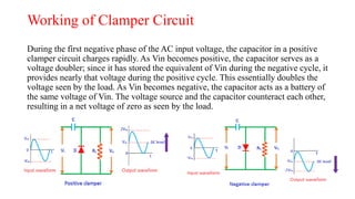
Digital Electronics and Pulse Techniques (EEE-3205)
Clamper Circuits
Outline
What are clamper circuits?
Working of clamper circuits
Types of clamper circuits
Applications of clamper circuits
Discussion
Why capacitor is used in clamping circuit(Group work)
Conclusion
What are clamper circuits?
• A clamper is an electronic circuit that fixes either the positive or the negative peak
excursions of a signal to a defined value by shifting its DC value.
• The clamping network is one that will "clamp" a signal to a different dc level.
• A typical clamper is made up of a capacitor, diode, and resistor. Some clampers contain
an extra element called DC battery. The resistors and capacitors are used in the clamper
circuit to maintain an altered DC level at the clamper output. The clamper is also referred
to as a DC restorer, clamped capacitors, or AC signal level shifter.
• Clamping circuits were common in analog television receivers. These sets have a DC
restorer circuit, which returns the voltage of the video signal during the 'back porch' of the
line blanking (retrace) period to 0 V. Low frequency interference, especially power line
hum, induced onto the signal spoils the rendering of the image, and in extreme cases
causes the set to lose synchronization. This interference can be effectively removed via
this method
Working of Clamper Circuit
During the first negative phase of the AC input voltage, the capacitor in a positive
clamper circuit charges rapidly. As Vin becomes positive, the capacitor serves as a
voltage doubler; since it has stored the equivalent of Vin during the negative cycle, it
provides nearly that voltage during the positive cycle. This essentially doubles the
voltage seen by the load. As Vin becomes negative, the capacitor acts as a battery of
the same voltage of Vin. The voltage source and the capacitor counteract each other,
resulting in a net voltage of zero as seen by the load.
Types of clamper circuits
The clamper circuits are of the following types:
 Positive clampers.
 Negative clampers.
 Biased clampers.
Applications of Clampers Circuits
o The complex transmitter and receiver circuitry of television clamper is used as a
base line stabilizer to define sections of the luminance signals to preset levels.
o Clampers are also called as direct current restorers as they clamp the wave forms
to a fixed DC potential.
o These are frequently used in test equipment, sonar and radar systems.
o For the protection of the amplifiers from large errant signals clampers are used.
o Clampers can be used for removing the distortions
o For improving the overdrive recovery time clampers are used.
o Clampers can be used as voltage doublers or voltage multipliers.
Discussion
Q/A
Group Work
Why Capacitor is used in clamper circuit?
Conclusion
Q/A
Following Lecture
Positive clampers & Negative clampers

Clamper Circuits

  • 1.
    Digital Electronics andPulse Techniques (EEE-3205) Clamper Circuits Outline What are clamper circuits? Working of clamper circuits Types of clamper circuits Applications of clamper circuits Discussion Why capacitor is used in clamping circuit(Group work) Conclusion
  • 2.
    What are clampercircuits? • A clamper is an electronic circuit that fixes either the positive or the negative peak excursions of a signal to a defined value by shifting its DC value. • The clamping network is one that will "clamp" a signal to a different dc level. • A typical clamper is made up of a capacitor, diode, and resistor. Some clampers contain an extra element called DC battery. The resistors and capacitors are used in the clamper circuit to maintain an altered DC level at the clamper output. The clamper is also referred to as a DC restorer, clamped capacitors, or AC signal level shifter. • Clamping circuits were common in analog television receivers. These sets have a DC restorer circuit, which returns the voltage of the video signal during the 'back porch' of the line blanking (retrace) period to 0 V. Low frequency interference, especially power line hum, induced onto the signal spoils the rendering of the image, and in extreme cases causes the set to lose synchronization. This interference can be effectively removed via this method
  • 3.
    Working of ClamperCircuit During the first negative phase of the AC input voltage, the capacitor in a positive clamper circuit charges rapidly. As Vin becomes positive, the capacitor serves as a voltage doubler; since it has stored the equivalent of Vin during the negative cycle, it provides nearly that voltage during the positive cycle. This essentially doubles the voltage seen by the load. As Vin becomes negative, the capacitor acts as a battery of the same voltage of Vin. The voltage source and the capacitor counteract each other, resulting in a net voltage of zero as seen by the load.
  • 4.
    Types of clampercircuits The clamper circuits are of the following types:  Positive clampers.  Negative clampers.  Biased clampers.
  • 5.
    Applications of ClampersCircuits o The complex transmitter and receiver circuitry of television clamper is used as a base line stabilizer to define sections of the luminance signals to preset levels. o Clampers are also called as direct current restorers as they clamp the wave forms to a fixed DC potential. o These are frequently used in test equipment, sonar and radar systems. o For the protection of the amplifiers from large errant signals clampers are used. o Clampers can be used for removing the distortions o For improving the overdrive recovery time clampers are used. o Clampers can be used as voltage doublers or voltage multipliers.
  • 6.
  • 7.
    Group Work Why Capacitoris used in clamper circuit?
  • 8.
  • 9.