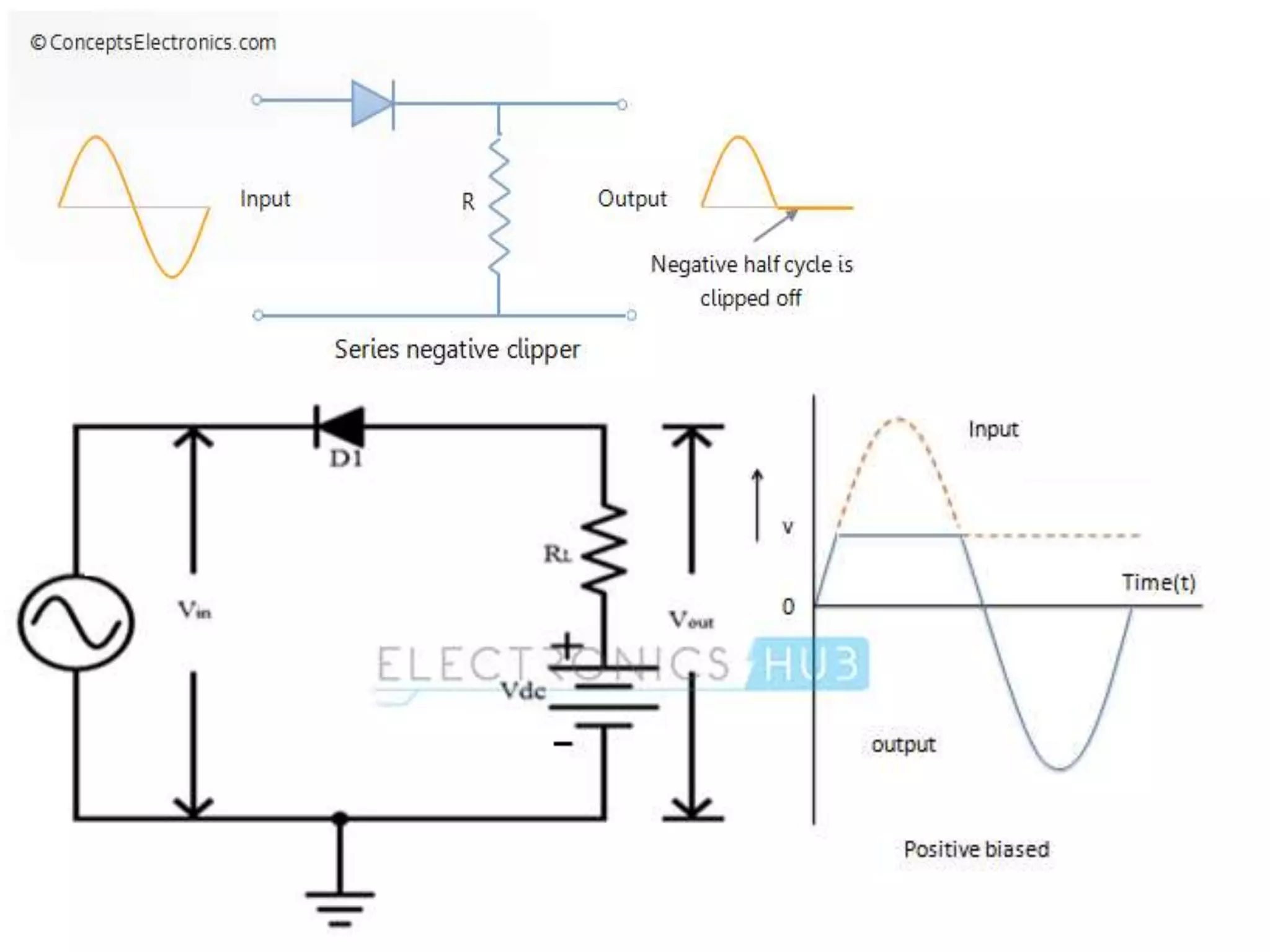
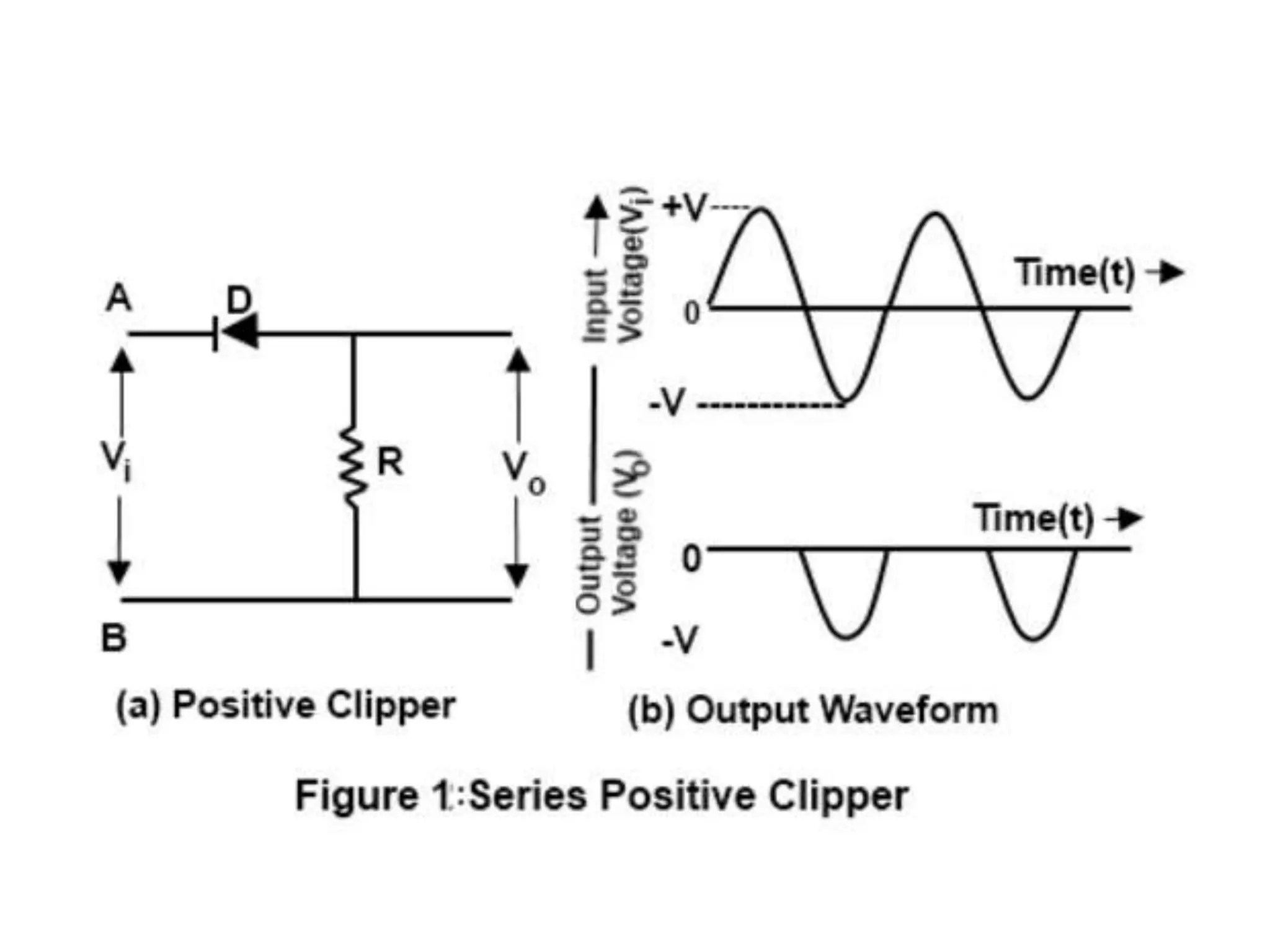
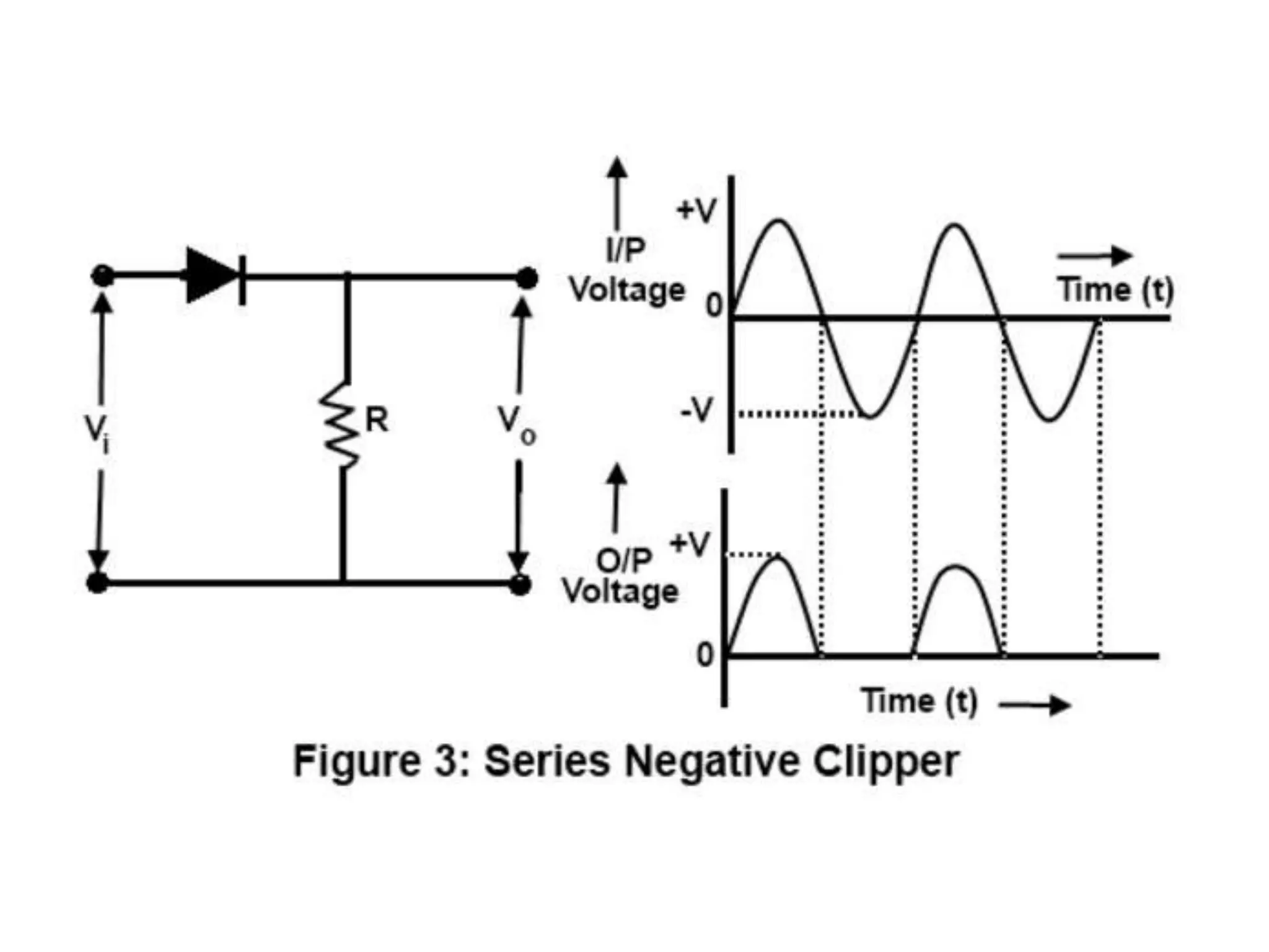
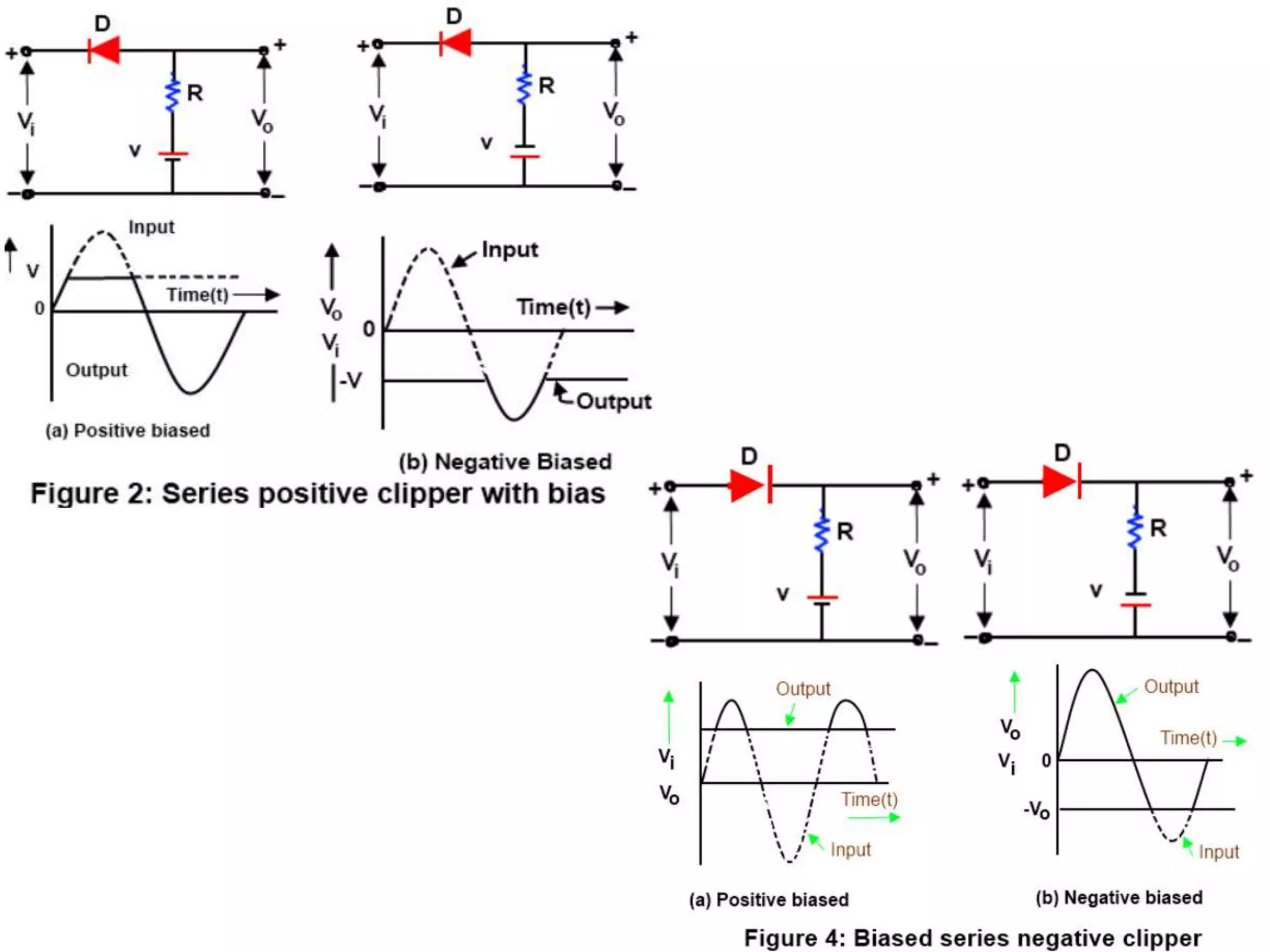
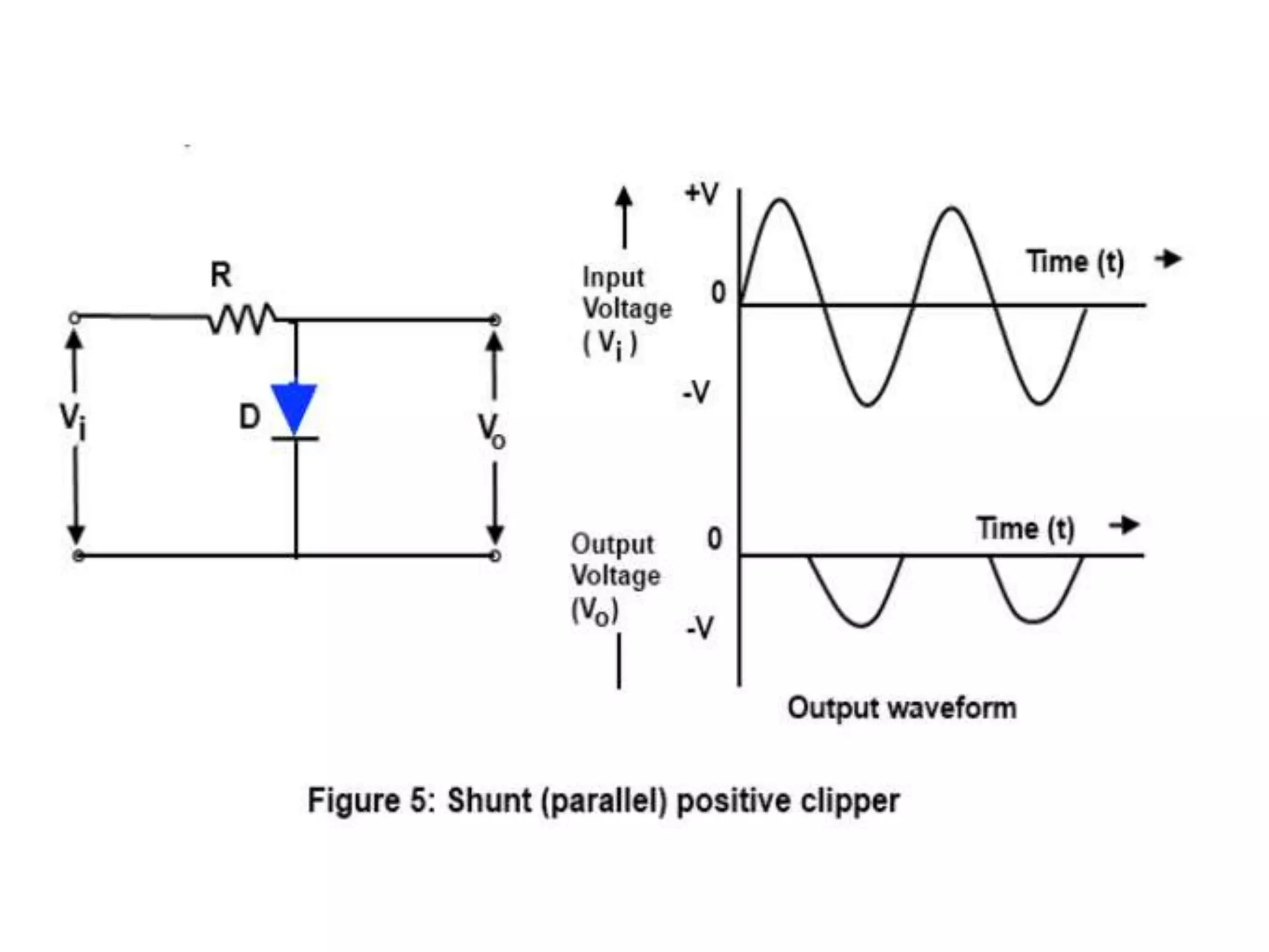
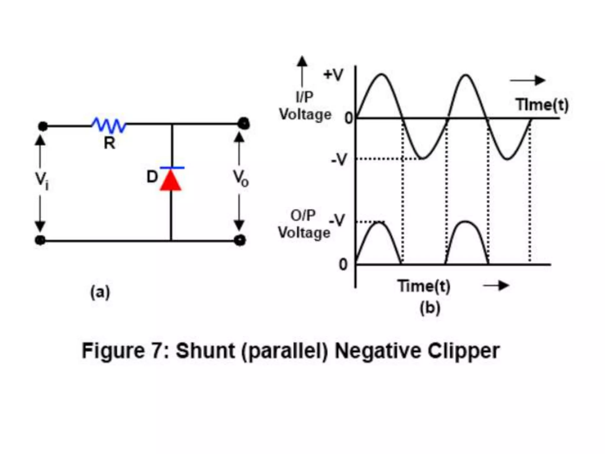
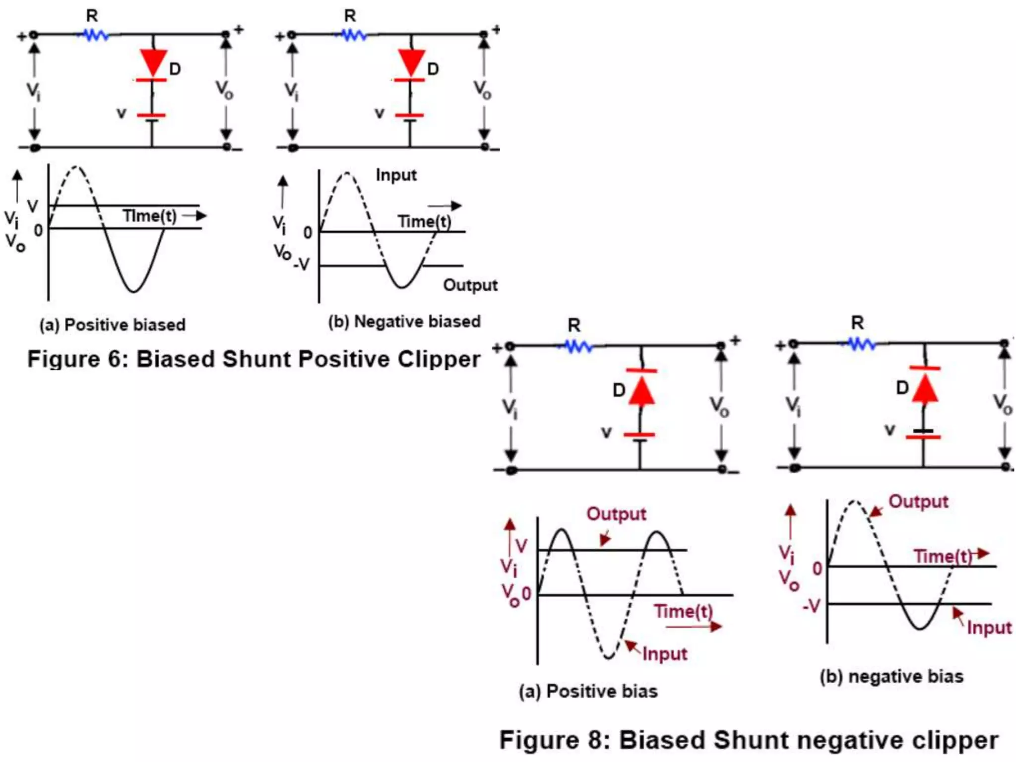
A clipper circuit uses diodes to remove parts of the waveform above or below a certain threshold. There are positive and negative clipper circuits that remove the positive or negative half of the input waveform. Biased clippers add a battery to change where the signal is clipped. A combination clipper removes parts of both halves of the input waveform. A clamper circuit adds a DC offset to an AC signal without changing its shape using a diode, capacitor, and resistor. Clampers are used to increase the wavelength of an input wave, such as in audio amplifiers.
Clippers and clampers are diode-based circuits used to modify signal waveforms. Clippers eliminate portions of an input signal to "clip" the waveform, and are used to remove noise or create new waveforms. They come in series and parallel types. Series clippers place the diode in series with the load, and clip voltages that don't forward bias the diode. Parallel clippers take the output across the diode, producing the voltage when it is not conducting. Clampers "clamp" a signal to a different DC level using a capacitor, diode, and resistor. The capacitor stores a reference voltage to set the output level when the diode is non-conducting.
Clipper and clamper circuits are used to modify signal waveforms. Clipper circuits remove portions of a signal that exceed a reference level, cutting off either positive or negative portions. Clamper circuits shift the entire signal up or down without changing its shape, setting either the positive or negative peak at a desired level. Common circuit types include positive and negative clippers and clampers, which use diodes and capacitors to clip or shift the signal in a particular direction relative to the reference level.
Thyristor commutation techniques can be natural or forced. Natural commutation occurs in AC circuits when the thyristor turns off as the AC voltage passes through zero. Forced commutation is used in DC circuits using methods like self, resonant pulse, complementary, and impulse commutation. Self commutation uses an underdamped LC circuit to create oscillating current that turns off the thyristor when current reaches zero. Resonant pulse commutation uses an auxiliary thyristor to discharge the capacitor and create reverse voltage across the main thyristor. Complementary commutation uses one thyristor to turn off the other in alternating fashion. Impulse commutation uses an inductor to create oscillating current for
This document discusses DC-DC converters, which convert a fixed DC source into a variable DC source like an AC transformer. It describes step-down converters, which use a switch like a BJT, MOSFET, or IGBT to alternately connect and disconnect the voltage source to produce a lower average output voltage. Key concepts covered include duty cycle, pulse-width modulation, modes of operation, generation of the switching signal, and analysis of a step-down converter with an RL load in continuous conduction mode.
This document discusses protection methods for SCRs, including overvoltage, overcurrent, dv/dt, and di/dt protection. It explains that dv/dt protection is needed to prevent false triggering of the SCR from high rates of change of the anode-cathode voltage. This is achieved using an RC snubber network across the SCR. It also notes that SCRs generate heat from current conduction, so a heatsink is required to dissipate this heat and prevent failure.
Do Diodes and electronic stuff freaks you out?And what about those clippers and clampers?The details are as follows.
You can learn every concept related to it here.Enjoy clipping :)
The document discusses thyristors, which are semiconductor devices that can be used as electrically controlled switches. It provides details on:
- The history and development of thyristors from the 1950s onward.
- The basic construction of a thyristor, which consists of four layers of alternating P-type and N-type semiconductor material.
- The three main modes of operation for thyristors - reverse blocking, forward blocking, and forward conducting.
- Applications of thyristors onboard ships, including use in motor starters, variable frequency drives, converter circuits, and inverter circuits.
Introduction
Band Pass Amplifiers
Series & Parallel Resonant Circuits & their Bandwidth
Analysis of Single Tuned Amplifiers
Analysis of Double Tuned Amplifiers
Primary & Secondary Tuned Amplifiers with BJT & FET
Merits and de-merits of Tuned Amplifiers
To turn on a Thyristor, there are various triggering methods in which a trigger pulse is applied at its Gate terminal. Similarly, there are various techniques to turn off a Thyristor, these techniques are called Thyristor Commutation Techniques.
Current sources, current mirrors, and current steering circuits are important components in integrated circuit design for providing stable bias currents. A constant current is first generated and then replicated across the circuit using current mirrors. Current mirrors use identical MOS transistors such that if the gate-source potentials are equal, the drain currents will be equal, allowing the reference current to be copied. There are various types of current mirror circuits that have different advantages and applications. Current can also be steered between paths using multiple current mirrors, with some mirrors acting as current sources and others as current sinks.
The document discusses active and passive components in electronics. It defines passive components as circuit elements that receive and store energy in electric or magnetic fields, but cannot continuously deliver power. Passive components mentioned include capacitors, inductors, and transformers. Active components are defined as having gain or ability to control voltage/current, and include transistors and integrated circuits. The document provides examples of capacitors, inductors, and transformers as passive elements, and contrasts them with transistors as active elements.
The document discusses MOSFETs (metal-oxide-semiconductor field-effect transistors). It provides information on:
1) The structure of MOSFETs including typical dimensions of the gate length and width. It operates by using a voltage applied to the gate to control the conductivity between the drain and source.
2) The operation of n-channel and p-channel MOSFETs. In an n-channel MOSFET, applying a positive voltage to the gate creates an n-type inversion channel between the source and drain allowing current to flow.
3) Biasing techniques for MOSFET amplifiers including fixing the gate voltage, connecting a resistor in the source,
1. An inverter refers to a power electronic device that converts DC input voltages to AC output voltages at the required magnitude and frequency.
2. There are three basic types of dc-ac converters depending on their AC output waveform: square wave, modified sine wave, and pure sine wave.
3. Inverters have applications in adjustable speed AC drives, electric vehicles, induction heating, aircraft power supplies, photovoltaic systems, UPS, and air conditioning units.
This document discusses different biasing techniques for MOSFETs, including biasing with a feedback resistor and voltage divider bias. It provides the equations to calculate the drain current, drain-source voltage, and gate voltage for each biasing method. It also discusses an example problem calculating the current, voltage, and power dissipation for a common-source MOSFET circuit. Thermal stability of transistors is briefly covered as well.
This document provides an overview of power electronics topics including semiconductor devices, controlled rectifiers, DC choppers, inverters, and AC choppers. It discusses various semiconductor devices used in power electronics like power diodes, transistors, BJTs, MOSFETs, IGBTs, SITs, thyristors, SCRs, TRIACs, and GTOs. It covers the structures, characteristics, and applications of these devices. It also compares different semiconductor devices and discusses switching and safe operating areas.
This document describes receiving end circle diagrams used to visualize load flow over a transmission line. It provides the following key points:
1) Receiving end circle diagrams are derived from voltage phasor diagrams and have different centers for the voltage circles, with a common active and reactive power axis.
2) They can be used to understand how an inductive or capacitive load will affect the reactive power supplied by the source.
3) The center of the receiving end circle is located based on the receiving end voltage magnitude and angle. The radius depends on the sending and receiving end voltage magnitudes.
4) The receiving end circle allows determining the total power received based on the operating point located from the known real power received
This document discusses TRIACs and DIACs. TRIACs are bidirectional semiconductor switches that can control AC in a load. They consist of two SCRs connected in inverse parallel with a common gate. DIACs are also bidirectional semiconductor devices that can be switched from off to on with either polarity of applied voltage. They have no control terminal. Both devices exhibit avalanche breakdown and negative resistance characteristics. TRIACs are used for phase control and lamp switching. DIACs are primarily used to trigger TRIACs in applications like light dimmers and heat controls.
This document presents on different types of clipper circuits. It discusses unbiased positive and negative clipper circuits, as well as biased positive and negative clipper circuits. It provides circuit diagrams to illustrate each type and describes how they work to clip portions of input signals. The document also outlines using Pspice to observe input and output signals of clipper circuits and references sources for more information.
Clipper circuits are used to remove parts of a signal that are above or below a defined reference level. There are several types of clipper circuits: unbiased positive and negative clippers which clip either the positive or negative portions of a signal, and biased positive and negative clippers which use an external bias voltage to adjust the clipping level. Unbiased clippers cut off either the positive or negative half of the input waveform based on the diode configuration. Biased clippers allow changing the clipping level by adjusting the bias voltage applied in series with the input signal and diode.
This document describes different types of waveforms that can be generated by a function generator. It discusses how triangular, square, and sine waves are produced. For triangular waves, the function generator charges and discharges a capacitor to produce a linear ramp waveform. A square wave is created using an integrator circuit that causes the output to switch between saturation voltages. Sine waves can be approximated from triangular waves using a resistor-diode network to nonlinearly scale the output.
This document provides an overview of basic electronics components and circuits. It begins with an introduction to passive components like resistors, capacitors, inductors, and transformers. It then covers analog circuits using transistors and operational amplifiers. The document provides details on circuit analysis and different types of filters. It explains concepts like resistors, capacitors, inductors, diodes, transistors, and operational amplifiers. Examples of common circuits are also presented like voltage dividers, rectifiers, and amplifiers.
The study of the basics of electronics can be studied through the link http://bit.ly/2PPv0mv
The transistor is a semiconductor device with three connections, capable of amplification in addition to rectification
This document discusses diodes and their applications. It begins with an introduction to diodes, including what a diode is, the P-N junction, and diode characteristics when forward and reverse biased. It then covers types of diodes like LEDs, Zener diodes, and more. Applications discussed include logic gates, temperature measurement, and power conversion. The document focuses on rectifiers, explaining half-wave and full-wave rectification and how diodes are used to convert AC to DC in power supplies. Circuit diagrams are provided to illustrate the principles and components of half-wave and full-wave rectifiers, including the addition of a capacitor filter.
dso is use for measurement ac as well as dc voltage and current.
and also use for faulty components in various circuit .it stored wave form in digital memory.it easy to operate. cursor measurement is possible.
The document presents information on MOSFET operation and characteristics. It discusses that MOSFETs are widely used in electronics as switches and for auto intensity control of street lights. It describes the basic construction of MOSFETs, noting they have an insulating layer of SiO2 and a polysilicon gate. The two main types of MOSFETs are introduced as enhancement type and depletion type. Key characteristics of enhancement type MOSFETs are described, including that drain current increases with increasing gate-source voltage above a threshold.
This document provides an introduction and overview of chopper circuits, which are power electronics devices that can convert a fixed DC voltage into a variable DC voltage.
It defines a chopper as a high-speed switch that connects and disconnects a load from a power source rapidly to produce a variable output voltage. Choppers can either step up or step down the output voltage relative to the input.
Different types of choppers are described including step-down, step-up, buck-boost, and various configurations classified by their operating quadrants on a voltage-current plane (types A, B, and C). Key components like switches, diodes, and inductors are also outlined.
This document discusses clipper and clamper circuits which use diodes, capacitors and resistors. Clipper circuits clip off a portion of the waveform from an input signal and come in series and parallel configurations for positive or negative clipping. Clamper circuits shift an entire signal to a different DC level. Specific examples are given of series positive and negative clipper circuits and parallel positive and negative clipper circuits. Clamper circuits are also explained showing how a capacitor can clamp the input signal to a DC level set by the voltage source or diode.
Wave shaping circuits modify the shape of a waveform by passing it through either linear or non-linear elements. There are two main types: linear circuits which change amplitude and phase but not shape, and non-linear circuits which use elements like diodes to modify shape. Common non-linear wave shaping circuits are clippers and clampers. Clippers cut off portions of the waveform above or below certain thresholds, while clampers shift the entire waveform up or down without changing its shape. Both have applications in signal processing and protection of electronic components.
Design a clipper and clamping circuit & study the output wave shapes.THE CREATORS ACADEMY
This document discusses different types of clipping and clamping circuits. It describes clipper circuits which remove parts of the input waveform, either the positive or negative portions. Positive clippers remove the positive half cycles, while negative clippers remove the negative half cycles. Biased clippers add a battery to make the diode conduct during only one polarity of the input signal. Clamper circuits add a DC offset to the input waveform without changing its shape. Positive clampers double the wavelength on the positive side, while negative clampers double the negative side. The purpose of these circuits is to protect downstream components from voltages that are too high or low.
Clippers are circuits that remove or cut unwanted portions of a waveform. They are used for amplitude limiting and noise elimination. The basic components of a clipping circuit are an ideal diode and resistor. Different types of clippers include series and parallel clippers, which are further classified as unbiased or biased depending on whether an external voltage is applied. Series clippers have the diode in series with the load while parallel clippers place the diode in parallel to the load.
Clipper circuits use diodes to clip portions of input signal waveforms without distorting the remaining parts. There are both unbiased and biased clipper circuits that can either positively or negatively clip signal levels. Common clipper circuit configurations include unbiased series positive and negative, unbiased shunt positive and negative, and biased series and shunt positive and negative clippers.
This document describes different types of clipping circuits, including series, parallel, biased series, and biased parallel clippers. It explains that clippers are used to eliminate amplitude noise or produce new waveforms by removing portions of an input signal above or below a reference level. The document provides details on series and parallel clippers, and includes instructions for simulating a positive shunt clipper circuit using a function generator, diode, resistor, and oscilloscope.
Clippers and clampers use diodes to limit or shift signal voltages. There are four basic clipper configurations that use diodes in either series or parallel to clip either the positive or negative portions of a signal. Clampers use a diode along with a capacitor and resistor to shift a signal voltage to a different DC level without distorting its shape. Common applications of clippers and clampers include transient protection, amplitude modulation detection, and DC restoration in television receivers.
This document outlines a lecture on clamper circuits. It begins by defining a clamper circuit as one that fixes either the positive or negative peaks of a signal to a defined value by shifting its DC value. It then discusses the basic components of a clamper circuit including a capacitor, diode and resistor. The document goes on to explain the working of a positive clamper circuit and lists the different types of clamper circuits. It concludes by covering the applications of clamper circuits such as in television receivers and test equipment and signaling that the following lecture will focus on positive and negative clamper circuits specifically.
Clipping and clamping circuits use diodes to modify input waveforms. Clipping circuits cut off portions of the waveform that exceed a threshold voltage, while clamping circuits shift the DC level of a waveform up or down. Basic clipping circuits use diodes, resistors, and batteries, with the diode orientation and battery voltage determining if it is a positive or negative clipper. Positive clippers cut off positive portions of the input, while negative clippers cut off negative portions. Clipping can be done in either a series or parallel configuration.
Varactor, step recovery diodes and frequency multiplierVirendra thakur
A varactor diode is a P-N junction diode that changes its capacitance and the series resistance as the bias applied to the diode is varied The property of capacitance change is utilized to achieve a change in the frequency or the phase of an electrical circuit Let’s we have a overview of a varactor diode, that includes working, construction, application and characteristics
Varactor Diode is a one kind of semiconductor microwave solid-state device
Varactor diodes are also named as Varicap diodes
The outcomes of the variable capacitance can be showed by the normal P-N junction diodes
This document discusses several types of special diodes:
- Tunnel diodes exploit the tunneling effect to conduct at very low voltages and exhibit negative resistance. They are used in oscillators.
- Schottky diodes have a metal-semiconductor junction and fast switching times, used in high-frequency applications.
- PIN diodes act as variable resistors when forward biased and capacitors when reverse biased, used in RF switching and modulation.
- Varactor diodes have variable capacitance when reverse biased, used in electronic tuning circuits.
Diode applications include rectifiers, clippers, clampers, voltage multipliers, and Zener voltage regulators. Rectifiers convert AC to pulsating DC and are classified as half-wave or full-wave. Clippers control waveform shape by removing portions. Clampers combine a diode and capacitor to clamp an AC signal to a DC level. Voltage multipliers produce an output DC voltage that is an integer multiple of the peak AC input. Zener diodes act as voltage regulators, providing a constant output voltage at their breakdown voltage.
Diode applications can be configured in series or parallel circuits. In series configurations, the diode resistance is small compared to other elements when forward biased, and has high resistance when reverse biased. Parallel and series-parallel configurations determine network resistances. Half-wave rectification only passes one half of the AC cycle. Peak inverse voltage must exceed the peak AC voltage to prevent reverse breakdown. Clippers and clampers use diodes to modify input signals without distortion.
There are two types of differentiator amplifiers: passive ones using only RC networks and active ones using transistors and op-amps. Active differentiators have higher output voltages and lower output resistance than passive ones. A differentiator amplifier outputs a voltage proportional to the rate of change of its input voltage. It acts as a high-pass filter, attenuating low frequencies and passing high frequencies. Differentiators are used in signal processing and instrumentation to monitor rate of change.
This document provides an overview of basic electronics components including resistors, capacitors, diodes, and transistors. Resistors are used to limit current or divide voltage. Capacitors store energy in the form of charge and are used in timing circuits. Diodes only allow current to flow in one direction and are used to rectify signals. Transistors have three terminals - emitter, base, and collector - and can be used to amplify or switch electronic signals. The document describes the purpose, types, and practical uses of each component.
This document summarizes key concepts about transmission lines. It discusses different types of transmission lines including coaxial cables and parallel lines. It covers electrical models of transmission lines and how factors like resistance, inductance and capacitance are distributed along transmission lines. It also discusses characteristic impedance, reflections, standing waves, impedance matching, and measurement techniques for transmission lines.
This document provides an overview of electronic devices and circuits. It discusses semiconductors like silicon and germanium and how they are doped to create p-type and n-type materials. The junction diode is described as the simplest electronic device, formed by joining p-type and n-type silicon. Diode applications in rectifiers and clipping/clamping circuits are explained. The document also covers LEDs and provides the junction diode current equation.
PEEK is a colorless, semi-crystalline thermoplastic with excellent mechanical properties that is formed through step-growth polymerization. It has a density of 1.32 g/cm3, glass transition temperature of 143°C, and melting temperature of 343°C. PEEK has high strength, creep resistance, and chemical resistance, making it suitable for applications in industries like aerospace, automotive, and medical implants where it can replace metals like steel. PEEK is synthesized through a step-growth reaction between 4,4-difluorobenzophenone and disodium salt of hydroquinone at 300°C in diphenyl sulfone.
This document provides an overview of the composition and application of paint. It discusses that paint is composed of a binder, pigment, extenders, and solvents. The binder is the film-forming component that forms an adherent film on the surface. Pigments provide characteristics like color and protection. Extenders modify properties and solvents make the paint flowable. Common binders include oils, resins, and polymers while common pigments are titanium dioxide, iron oxide, and phthalocyanine. Paint is applied to surfaces like houses, cars, and machines through various methods.
Acrylic paint was first developed in the 1930s and became commercially available in the 1950s. It uses acrylic polymer emulsion to suspend pigments. Acrylic paint dries quickly and is water-soluble when wet but water-resistant when dry. It can mimic watercolor or oil painting techniques. Popularized in the 1960s by artists like Andy Warhol, it is commonly used for crafts and school art classes due to being non-toxic. Acrylic paint comes in various viscosities and grades for professional or student use. It offers advantages like quick drying, layering, and durability but also dries faster than oils, limiting blending techniques.
Understanding Inductive Bias in Machine LearningSUTEJAS
This presentation explores the concept of inductive bias in machine learning. It explains how algorithms come with built-in assumptions and preferences that guide the learning process. You'll learn about the different types of inductive bias and how they can impact the performance and generalizability of machine learning models.
The presentation also covers the positive and negative aspects of inductive bias, along with strategies for mitigating potential drawbacks. We'll explore examples of how bias manifests in algorithms like neural networks and decision trees.
By understanding inductive bias, you can gain valuable insights into how machine learning models work and make informed decisions when building and deploying them.
Advanced control scheme of doubly fed induction generator for wind turbine us...IJECEIAES
This paper describes a speed control device for generating electrical energy on an electricity network based on the doubly fed induction generator (DFIG) used for wind power conversion systems. At first, a double-fed induction generator model was constructed. A control law is formulated to govern the flow of energy between the stator of a DFIG and the energy network using three types of controllers: proportional integral (PI), sliding mode controller (SMC) and second order sliding mode controller (SOSMC). Their different results in terms of power reference tracking, reaction to unexpected speed fluctuations, sensitivity to perturbations, and resilience against machine parameter alterations are compared. MATLAB/Simulink was used to conduct the simulations for the preceding study. Multiple simulations have shown very satisfying results, and the investigations demonstrate the efficacy and power-enhancing capabilities of the suggested control system.
6th International Conference on Machine Learning & Applications (CMLA 2024)ClaraZara1
6th International Conference on Machine Learning & Applications (CMLA 2024) will provide an excellent international forum for sharing knowledge and results in theory, methodology and applications of on Machine Learning & Applications.
A review on techniques and modelling methodologies used for checking electrom...nooriasukmaningtyas
The proper function of the integrated circuit (IC) in an inhibiting electromagnetic environment has always been a serious concern throughout the decades of revolution in the world of electronics, from disjunct devices to today’s integrated circuit technology, where billions of transistors are combined on a single chip. The automotive industry and smart vehicles in particular, are confronting design issues such as being prone to electromagnetic interference (EMI). Electronic control devices calculate incorrect outputs because of EMI and sensors give misleading values which can prove fatal in case of automotives. In this paper, the authors have non exhaustively tried to review research work concerned with the investigation of EMI in ICs and prediction of this EMI using various modelling methodologies and measurement setups.
CHINA’S GEO-ECONOMIC OUTREACH IN CENTRAL ASIAN COUNTRIES AND FUTURE PROSPECTjpsjournal1
The rivalry between prominent international actors for dominance over Central Asia's hydrocarbon
reserves and the ancient silk trade route, along with China's diplomatic endeavours in the area, has been
referred to as the "New Great Game." This research centres on the power struggle, considering
geopolitical, geostrategic, and geoeconomic variables. Topics including trade, political hegemony, oil
politics, and conventional and nontraditional security are all explored and explained by the researcher.
Using Mackinder's Heartland, Spykman Rimland, and Hegemonic Stability theories, examines China's role
in Central Asia. This study adheres to the empirical epistemological method and has taken care of
objectivity. This study analyze primary and secondary research documents critically to elaborate role of
china’s geo economic outreach in central Asian countries and its future prospect. China is thriving in trade,
pipeline politics, and winning states, according to this study, thanks to important instruments like the
Shanghai Cooperation Organisation and the Belt and Road Economic Initiative. According to this study,
China is seeing significant success in commerce, pipeline politics, and gaining influence on other
governments. This success may be attributed to the effective utilisation of key tools such as the Shanghai
Cooperation Organisation and the Belt and Road Economic Initiative.
Harnessing WebAssembly for Real-time Stateless Streaming PipelinesChristina Lin
Traditionally, dealing with real-time data pipelines has involved significant overhead, even for straightforward tasks like data transformation or masking. However, in this talk, we’ll venture into the dynamic realm of WebAssembly (WASM) and discover how it can revolutionize the creation of stateless streaming pipelines within a Kafka (Redpanda) broker. These pipelines are adept at managing low-latency, high-data-volume scenarios.
We have compiled the most important slides from each speaker's presentation. This year’s compilation, available for free, captures the key insights and contributions shared during the DfMAy 2024 conference.
Using recycled concrete aggregates (RCA) for pavements is crucial to achieving sustainability. Implementing RCA for new pavement can minimize carbon footprint, conserve natural resources, reduce harmful emissions, and lower life cycle costs. Compared to natural aggregate (NA), RCA pavement has fewer comprehensive studies and sustainability assessments.
1. Introduction
• These circuits are applications of P-N Junction diodes
• Clipper Circuits are used to clip off a portion of wave
from an input signal
• It is used in two ways – series and parallel.
• Clamper Circuits clamp a signal to different dc level.
• Along with diodes, capacitors and resistors are also
used.
2.
3. Series Clipper Circuit
• First introduced as a half-wave rectifier for sinusoidal
waveforms.
• However, there are no boundaries on the type of
signals that can be applied to a clipper.
• In Series Positive Clipper, the diode is connected in
series with the output in Forward Biasing.
• In Series Negative Clipper, the diode is connected in
series with the output in Reverse Biasing.
• In Series Bias Clipper, a battery is connected with
resistance
4.
5.
6.
7. Parallel Clipper Circuit
• Also known as Shunt Clipper
• Output is in parallel with the diode & resistance (
which are, in turn, in series)
• Like series, there is also positive and negative shunt
clipper.
• Like series, we have biased parallel clipper circuit
wherein, battery is connected with diode