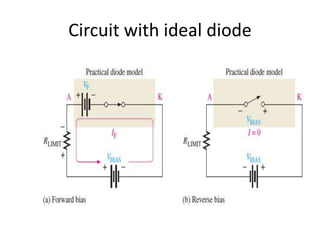
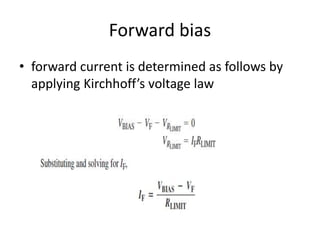
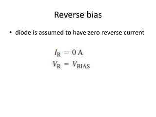
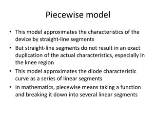
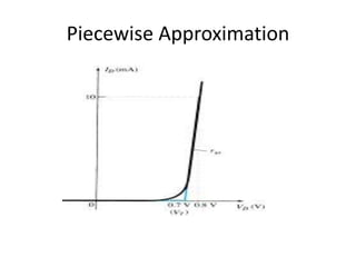
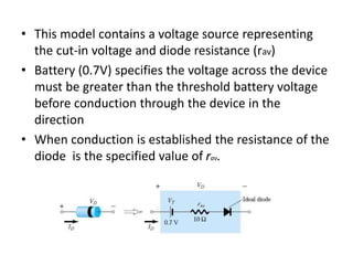
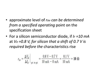
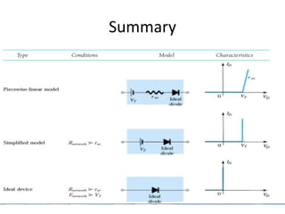
Diode Equivalent Circuits/
Diode Models
Dr.G.Puvaneswari
Assistant Professor(SG)
ECE, Coimbatore Institute of
Technology, Coimbatore
Diode Equivalent Circuits/Diode
Models
• It is a combination of elements that
represents the actual terminal characteristics
of a device in its operating region
• Diode models are the mathematical models
used to approximate the actual behavior of
real diodes for analysis purpose.
• The diode circuits are solved by using diode
models in the place of diodes without
affecting the system behavior
Why diode models
• Diode’s V-I characteristics is nonlinear
• nonlinearity complicates the calculations in
circuits involving diodes
• Use of diode models or equivalent circuits
enables the use of conventional circuit
analysis techniques
Diode Models
• Three models are used
–Ideal Diode Model
–Simplified
–Piecewise linear model
Ideal diode model
• It is the least accurate approximation
• It is represented by a simple switch
• An ideal forward-biased diode acts like a closed (on)
switch
• An ideal reversed-biased diode acts like an open (off)
switch
• The barrier potential, the forward dynamic resistance,
and the reverse current are neglected
• Diode is replaced by simple switch
• These models are used in troubleshooting, to
determine whether the diode is working properly and
where the exact values of voltage or current are not
needed
Simplified diode model/Practical
diode model
• The practical model includes the barrier
potential
• It states that a forward-biased silicon diode
under dc condition has a voltage drop (cut-in
voltage) of 0.7 V (for Si diodes) across it at any
level of diode current within the rated values
• It consists of a voltage source representing the
cut-in voltage of the diode and an ideal diode
acting as a switch
Simplified equivalent circuit
Circuit with ideal diode
Forward bias
• forward current is determined as follows by
applying Kirchhoff’s voltage law
Reverse bias
• diode is assumed to have zero reverse current
Piecewise model
• This model approximates the characteristics of the
device by straight-line segments
• But straight-line segments do not result in an exact
duplication of the actual characteristics, especially in
the knee region
• This model approximates the diode characteristic
curve as a series of linear segments
• In mathematics, piecewise means taking a function
and breaking it down into several linear segments
Piecewise Approximation
• This model contains a voltage source representing
the cut-in voltage and diode resistance (rav)
• Battery (0.7V) specifies the voltage across the device
must be greater than the threshold battery voltage
before conduction through the device in the
direction
• When conduction is established the resistance of the
diode is the specified value of rav.
• approximate level of rav can be determined
from a specified operating point on the
specification sheet
• For a silicon semiconductor diode, if IF =10 mA
at VD =0.8 V, for silicon that a shift of 0.7 V is
required before the characteristics rise
Summary
References
• Robert L. Boylestead and Louis Nasheresky
"Electron Devices and Circuits: Theory and
Practice", Prentice Hall of India, 11th Edition,
2013.
• “Fundamentals of Analog Circuits” by Thomas
Floyd

Diode Equivalent Circuits.ppt

  • 1.
    Diode Equivalent Circuits/ DiodeModels Dr.G.Puvaneswari Assistant Professor(SG) ECE, Coimbatore Institute of Technology, Coimbatore
  • 2.
    Diode Equivalent Circuits/Diode Models •It is a combination of elements that represents the actual terminal characteristics of a device in its operating region • Diode models are the mathematical models used to approximate the actual behavior of real diodes for analysis purpose. • The diode circuits are solved by using diode models in the place of diodes without affecting the system behavior
  • 3.
    Why diode models •Diode’s V-I characteristics is nonlinear • nonlinearity complicates the calculations in circuits involving diodes • Use of diode models or equivalent circuits enables the use of conventional circuit analysis techniques
  • 4.
    Diode Models • Threemodels are used –Ideal Diode Model –Simplified –Piecewise linear model
  • 5.
    Ideal diode model •It is the least accurate approximation • It is represented by a simple switch • An ideal forward-biased diode acts like a closed (on) switch • An ideal reversed-biased diode acts like an open (off) switch • The barrier potential, the forward dynamic resistance, and the reverse current are neglected • Diode is replaced by simple switch • These models are used in troubleshooting, to determine whether the diode is working properly and where the exact values of voltage or current are not needed
  • 7.
    Simplified diode model/Practical diodemodel • The practical model includes the barrier potential • It states that a forward-biased silicon diode under dc condition has a voltage drop (cut-in voltage) of 0.7 V (for Si diodes) across it at any level of diode current within the rated values • It consists of a voltage source representing the cut-in voltage of the diode and an ideal diode acting as a switch
  • 8.
  • 9.
  • 10.
    Forward bias • forwardcurrent is determined as follows by applying Kirchhoff’s voltage law
  • 11.
    Reverse bias • diodeis assumed to have zero reverse current
  • 12.
    Piecewise model • Thismodel approximates the characteristics of the device by straight-line segments • But straight-line segments do not result in an exact duplication of the actual characteristics, especially in the knee region • This model approximates the diode characteristic curve as a series of linear segments • In mathematics, piecewise means taking a function and breaking it down into several linear segments
  • 13.
  • 14.
    • This modelcontains a voltage source representing the cut-in voltage and diode resistance (rav) • Battery (0.7V) specifies the voltage across the device must be greater than the threshold battery voltage before conduction through the device in the direction • When conduction is established the resistance of the diode is the specified value of rav.
  • 15.
    • approximate levelof rav can be determined from a specified operating point on the specification sheet • For a silicon semiconductor diode, if IF =10 mA at VD =0.8 V, for silicon that a shift of 0.7 V is required before the characteristics rise
  • 16.
  • 17.
    References • Robert L.Boylestead and Louis Nasheresky "Electron Devices and Circuits: Theory and Practice", Prentice Hall of India, 11th Edition, 2013. • “Fundamentals of Analog Circuits” by Thomas Floyd