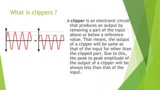
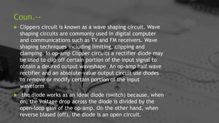
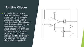
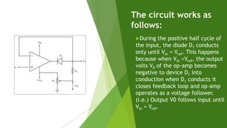
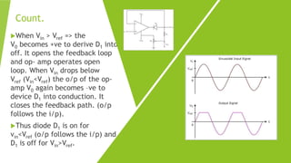
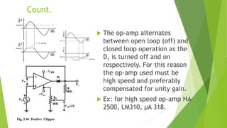
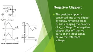
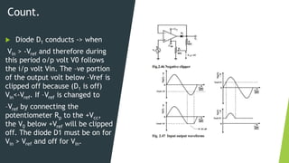
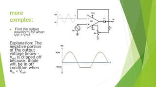
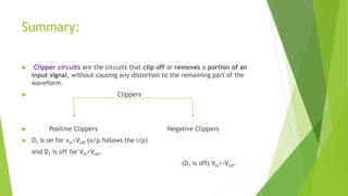
Contents
 Introduction
 What is clippers ?
 Types of clippers
 Positive clippers
 Negative clippers
 Application of clippers
 Summary
Introduction
 Wave shaping circuits are the electronic circuits, which
produce the desired shape at the output from the applied
input wave form. These circuits perform two functions −
 Attenuate the applied wave
 Alter the dc level of the applied wave.
 There are two types of wave shaping circuits:
Clippers and Clampers.
In this topic, we will learn in detail about clippers.
What is clippers ?
A clipper is an electronic circuit
that produces an output by
removing a part of the input
above or below a reference
value. That means, the output
of a clipper will be same as
that of the input for other than
the clipped part. Due to this,
the peak to peak amplitude of
the output of a clipper will be
always less than that of the
input.
Coun.--
 Clippers circuit is known as a wave shaping circuit. Wave
shaping circuits are commonly used in digital computer
and communications such as TV and FM receivers. Wave
shaping techniques including limiting, clipping and
clamping. In op-amp Clipper circuits a rectifier diode may
be used to clip off certain portion of the input signal to
obtain a desired output waveshape. An op-amp half wave
rectifier and an absolute-value output circuit use diodes
to remove or modify certain portion of the input
waveform
 the diode works as an ideal diode (switch) because, when
on, the voltage drop across the diode is divided by the
open-loop gain of the op-amp. On the other hand, when
reverse biased (off), the diode is an open circuit.
Types of Clippers
 Clippers can be classified into
the following two types based
on the clipping portion of the
input.
 Positive Clipper
 Negative Clipper
Positive Clipper
 A circuit that removes
positive parts of the input
signal can be formed by
using an op-amp with a
rectifier diode. The clipping
level is determined by the
reference voltage Vref,
which should less than the
i/p range of the op-amp
(Vref < Vin). The Output
voltage has the portions of
the positive half cycles
above Vref clipped off.
The circuit works as
follows:
During the positive half cycle of
the input, the diode D1 conducts
only until Vin = Vref. This happens
because when Vin <Vref, the output
volts V0 of the op-amp becomes
negative to device D1 into
conduction when D1 conducts it
closes feedback loop and op-amp
operates as a voltage follower.
(i.e.) Output V0 follows input until
Vin = Vref.
Count.
When Vin > Vref => the
V0 becomes +ve to derive D1 into
off. It opens the feedback loop
and op- amp operates open
loop. When Vin drops below
Vref (Vin<Vref) the o/p of the op-
amp V0 again becomes –ve to
device D1 into conduction. It
closes the feedback path. (o/p
follows the i/p).
Thus diode D1 is on for
vin<Vref (o/p follows the i/p) and
D1 is off for Vin>Vref.
Count.
 The op-amp alternates
between open loop (off) and
closed loop operation as the
D1 is turned off and on
respectively. For this reason
the op-amp used must be
high speed and preferably
compensated for unity gain.
 Ex: for high speed op-amp HA
2500, LM310, μA 318.
Negative Clipper:
 The positive clipper is
converted into a –ve clipper
by simply reversing diode
D1 and changing the polarity
of Vref voltage. The negative
clipper clips off the –ve
parts of the input signal
below the reference
voltage.
Count.
 Diode D1 conducts -> when
Vin > -Vref and therefore during
this period o/p volt V0 follows
the i/p volt Vin. The –ve portion
of the output volt below –Vref is
clipped off because (D1 is off)
Vin<-Vref. If –Vref is changed to
–Vref by connecting the
potentiometer Rp to the +Vcc,
the V0 below +Vref will be clipped
off. The diode D1 must be on for
Vin > Vref and off for Vin.
more
exmples:
 Find the output
waveform for when
Vin < Vref
Explanation: The
negative portion
of the output
voltage below -
Vref is clipped off
because, diode
will be in off
condition when
Vin < Vref.
Application of
clippers:
 They are frequently used for
the separation of synchronizing
signal from the composite
picture signals.
 The excessive noise spikes
above a certain level can be
limited or clipped in FM
transmitters by using the series
clippers.
 For the generation of
new waveforms or shaping the
existing waveform, clippers are
used.
Application of
Clippers:
 The typical application of diode
clipper is for the protection of
transistor from transients, as a
freewheeling diode connected in
parallel across the inductive load
 Frequently used half wave rectifier
in power supply kits is a typical
example of a clippers .It
clips either positive or negative half
wave of the input.
 Clippers can be used as voltage
limiters and amplitude selectors.
Summary:
 Clipper circuits are the circuits that clip off or removes a portion of an
input signal, without causing any distortion to the remaining part of the
waveform.
 Clippers
 Positive Clippers Negative Clippers
 D1 is on for vin<Vref (o/p follows the i/p)
and D1 is off for Vin>Vref.
(D1 is off) Vin<-Vref.
References:
 Op-Amps and
linear integrated
circuits by
Ramakant A.
Gayakwad
 Goggle searches.

StudentPresentation (1)_Lovlesh(044)Tushar(059).pptx

  • 1.
    Contents  Introduction  Whatis clippers ?  Types of clippers  Positive clippers  Negative clippers  Application of clippers  Summary
  • 2.
    Introduction  Wave shapingcircuits are the electronic circuits, which produce the desired shape at the output from the applied input wave form. These circuits perform two functions −  Attenuate the applied wave  Alter the dc level of the applied wave.  There are two types of wave shaping circuits: Clippers and Clampers. In this topic, we will learn in detail about clippers.
  • 3.
    What is clippers? A clipper is an electronic circuit that produces an output by removing a part of the input above or below a reference value. That means, the output of a clipper will be same as that of the input for other than the clipped part. Due to this, the peak to peak amplitude of the output of a clipper will be always less than that of the input.
  • 4.
    Coun.--  Clippers circuitis known as a wave shaping circuit. Wave shaping circuits are commonly used in digital computer and communications such as TV and FM receivers. Wave shaping techniques including limiting, clipping and clamping. In op-amp Clipper circuits a rectifier diode may be used to clip off certain portion of the input signal to obtain a desired output waveshape. An op-amp half wave rectifier and an absolute-value output circuit use diodes to remove or modify certain portion of the input waveform  the diode works as an ideal diode (switch) because, when on, the voltage drop across the diode is divided by the open-loop gain of the op-amp. On the other hand, when reverse biased (off), the diode is an open circuit.
  • 5.
    Types of Clippers Clippers can be classified into the following two types based on the clipping portion of the input.  Positive Clipper  Negative Clipper
  • 6.
    Positive Clipper  Acircuit that removes positive parts of the input signal can be formed by using an op-amp with a rectifier diode. The clipping level is determined by the reference voltage Vref, which should less than the i/p range of the op-amp (Vref < Vin). The Output voltage has the portions of the positive half cycles above Vref clipped off.
  • 7.
    The circuit worksas follows: During the positive half cycle of the input, the diode D1 conducts only until Vin = Vref. This happens because when Vin <Vref, the output volts V0 of the op-amp becomes negative to device D1 into conduction when D1 conducts it closes feedback loop and op-amp operates as a voltage follower. (i.e.) Output V0 follows input until Vin = Vref.
  • 8.
    Count. When Vin >Vref => the V0 becomes +ve to derive D1 into off. It opens the feedback loop and op- amp operates open loop. When Vin drops below Vref (Vin<Vref) the o/p of the op- amp V0 again becomes –ve to device D1 into conduction. It closes the feedback path. (o/p follows the i/p). Thus diode D1 is on for vin<Vref (o/p follows the i/p) and D1 is off for Vin>Vref.
  • 9.
    Count.  The op-ampalternates between open loop (off) and closed loop operation as the D1 is turned off and on respectively. For this reason the op-amp used must be high speed and preferably compensated for unity gain.  Ex: for high speed op-amp HA 2500, LM310, μA 318.
  • 10.
    Negative Clipper:  Thepositive clipper is converted into a –ve clipper by simply reversing diode D1 and changing the polarity of Vref voltage. The negative clipper clips off the –ve parts of the input signal below the reference voltage.
  • 11.
    Count.  Diode D1conducts -> when Vin > -Vref and therefore during this period o/p volt V0 follows the i/p volt Vin. The –ve portion of the output volt below –Vref is clipped off because (D1 is off) Vin<-Vref. If –Vref is changed to –Vref by connecting the potentiometer Rp to the +Vcc, the V0 below +Vref will be clipped off. The diode D1 must be on for Vin > Vref and off for Vin.
  • 12.
    more exmples:  Find theoutput waveform for when Vin < Vref Explanation: The negative portion of the output voltage below - Vref is clipped off because, diode will be in off condition when Vin < Vref.
  • 13.
    Application of clippers:  Theyare frequently used for the separation of synchronizing signal from the composite picture signals.  The excessive noise spikes above a certain level can be limited or clipped in FM transmitters by using the series clippers.  For the generation of new waveforms or shaping the existing waveform, clippers are used.
  • 14.
    Application of Clippers:  Thetypical application of diode clipper is for the protection of transistor from transients, as a freewheeling diode connected in parallel across the inductive load  Frequently used half wave rectifier in power supply kits is a typical example of a clippers .It clips either positive or negative half wave of the input.  Clippers can be used as voltage limiters and amplitude selectors.
  • 15.
    Summary:  Clipper circuitsare the circuits that clip off or removes a portion of an input signal, without causing any distortion to the remaining part of the waveform.  Clippers  Positive Clippers Negative Clippers  D1 is on for vin<Vref (o/p follows the i/p) and D1 is off for Vin>Vref. (D1 is off) Vin<-Vref.
  • 16.
    References:  Op-Amps and linearintegrated circuits by Ramakant A. Gayakwad  Goggle searches.