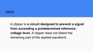
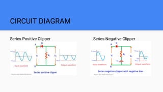
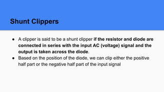
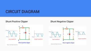
CLIPPERS
Dr.E.GOMATHI
Introduction to Clipping Circuits
Intro
A clipper is a circuit designed to prevent a signal
from exceeding a predetermined reference
voltage level. A clipper does not distort the
remaining part of the applied waveform.
Types of Clippers
● Series Clippers
● Shunt Clippers
Series Clippers
● A clipper is said to be a series clipper if the diode and resistor
are connected in series with the input AC (voltage) signal and
the output is taken across the resistor.
● Based on the position of the diode, we can clip either the positive
half part or the negative half part of the input signal.
CIRCUIT DIAGRAM
Series Positive Clipper Series Negative Clipper
Shunt Clippers
● A clipper is said to be a shunt clipper if the resistor and diode are
connected in series with the input AC (voltage) signal and the
output is taken across the diode.
● Based on the position of the diode, we can clip either the positive
half part or the negative half part of the input signal
CIRCUIT DIAGRAM
Shunt Positive Clipper Shunt Negative Clipper
Biasing in Clippers
● If the bias voltage is placed in series with a diode then the
circuit is called a biased clipper or limiter circuit.
● This bias determines the point where the diode begins to conduct
and the duration of conduction.
● With bias, clipping can be done to any percent of the input signal
ranging from 1% to 99%.
Applications of Clippers
● To generate and shape the waveforms, clippers are used.
● Power supply units consist of clipping circuits.
● FM transmitters to remove the excess amount of ripples clipping circuits
are used.
Advantages and Disadvantages
Advantages:
Clipping circuits serve as overvoltage protection for sensitive devices.
Disadvantages:
The data transmitted at values outside the range of the circuit will be
clipped as the signal transmission is considered.

Clipper.pptx

  • 1.
  • 2.
  • 3.
    Intro A clipper isa circuit designed to prevent a signal from exceeding a predetermined reference voltage level. A clipper does not distort the remaining part of the applied waveform.
  • 4.
    Types of Clippers ●Series Clippers ● Shunt Clippers
  • 5.
    Series Clippers ● Aclipper is said to be a series clipper if the diode and resistor are connected in series with the input AC (voltage) signal and the output is taken across the resistor. ● Based on the position of the diode, we can clip either the positive half part or the negative half part of the input signal.
  • 6.
    CIRCUIT DIAGRAM Series PositiveClipper Series Negative Clipper
  • 7.
    Shunt Clippers ● Aclipper is said to be a shunt clipper if the resistor and diode are connected in series with the input AC (voltage) signal and the output is taken across the diode. ● Based on the position of the diode, we can clip either the positive half part or the negative half part of the input signal
  • 8.
    CIRCUIT DIAGRAM Shunt PositiveClipper Shunt Negative Clipper
  • 9.
    Biasing in Clippers ●If the bias voltage is placed in series with a diode then the circuit is called a biased clipper or limiter circuit. ● This bias determines the point where the diode begins to conduct and the duration of conduction. ● With bias, clipping can be done to any percent of the input signal ranging from 1% to 99%.
  • 10.
    Applications of Clippers ●To generate and shape the waveforms, clippers are used. ● Power supply units consist of clipping circuits. ● FM transmitters to remove the excess amount of ripples clipping circuits are used.
  • 11.
    Advantages and Disadvantages Advantages: Clippingcircuits serve as overvoltage protection for sensitive devices. Disadvantages: The data transmitted at values outside the range of the circuit will be clipped as the signal transmission is considered.