Downloaded 16 times
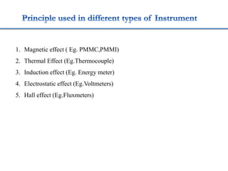


1. The document discusses various types of instruments used for measurement of electrical quantities like current, voltage, power, energy, frequency, phase etc. It describes different working principles like magnetic, thermal, electrostatic etc. 2. Various classifications of instruments are provided based on their construction and working like moving coil, moving iron, electrodynamometer types. 3. Measurement techniques for parameters like flux density, magnetizing force, iron losses are also summarized along with types of instrument transformers. 4. Construction and working of instruments for measurements like wattmeter, energy meter, frequency meter and phase meter are highlighted in brief.


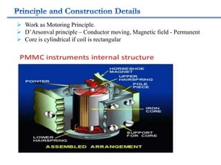
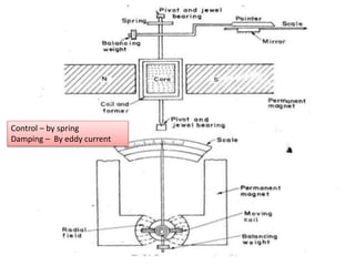
![ELECTRICAL MEASUREMENT & MEASURING INSTRUMENTS [Emmi- (NEE-302) -unit-1]](https://cdn.slidesharecdn.com/ss_thumbnails/emmi-nee-302-unit-1-170607090405-thumbnail.jpg?width=640&height=640&fit=bounds)