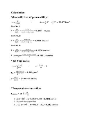
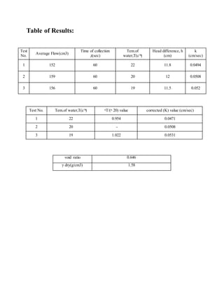
The document describes a laboratory experiment to determine the permeability of a soil sample using the constant head permeability test method. Three trials were conducted on the sample, which had an average dry unit weight of 1.58 g/cm3 and void ratio of 0.646. The average coefficient of permeability from the trials was determined to be 0.050733 cm/sec, classifying the sample as coarse sand according to ASTM standards. Factors that influence permeability and potential sources of error in the experiment are also discussed.
Class notes of Geotechnical Engineering course I used to teach at UET Lahore. Feel free to download the slide show.
Anyone looking to modify these files and use them for their own teaching purposes can contact me directly to get hold of editable version.
Class notes of Geotechnical Engineering course I used to teach at UET Lahore. Feel free to download the slide show.
Anyone looking to modify these files and use them for their own teaching purposes can contact me directly to get hold of editable version.
Class notes of Geotechnical Engineering course I used to teach at UET Lahore. Feel free to download the slide show.
Anyone looking to modify these files and use them for their own teaching purposes can contact me directly to get hold of editable version.
Class notes of Geotechnical Engineering course I used to teach at UET Lahore. Feel free to download the slide show.
Anyone looking to modify these files and use them for their own teaching purposes can contact me directly to get hold of editable version.
DETERMINATION OF UNCONFINED COMPRESSIVE STRENGTH OF SOILJaptyesh Singh
DETERMINATION OF UNCONFINED COMPRESSIVE STRENGTH OF SOIL in Foundation Engineering
INTRODUCTION
TERMINOLOGY
APPARATUS
SOIL SPECIMEN & ITS TYPES
THEORY
RELEVANCE OF THE EXPERIMENT
PROCEDURE
VIDEO
OBSERVATION
DISCUSSION
REMARKS
Class notes of Geotechnical Engineering course I used to teach at UET Lahore. Feel free to download the slide show.
Anyone looking to modify these files and use them for their own teaching purposes can contact me directly to get hold of editable version.
Class notes of Geotechnical Engineering course I used to teach at UET Lahore. Feel free to download the slide show.
Anyone looking to modify these files and use them for their own teaching purposes can contact me directly to get hold of editable version.
Compaction Test
Name:
Rezhwan Hama Karim
University Of Halabja
Civil Engineering Department
Soil lap
Contents:
Introduction
Purpose of this experiment
Standard references
Materials and equipment
Procedure
Data analysis
Discussion
Conclusion
Introduction
The Proctor compaction test is a laboratory method of experimentally determining the optimal moisture content at which a given soil type will become most dense and achieve its maximum dry density. And the graphical relationship of the dry density to moisture content is then plotted to establish the compaction curve.
Purpose of this experiment
This laboratory test is performed to determine the relationship between the moisture content and the dry density of a soil for a specified compactive effort. The compactive effort is the amount of mechanical energy that is applied to the soil mass. Several different methods are used to compact soil in the field, and some examples include tamping, kneading, vibration, and static load compaction. This laboratory will employ the tamping or impact compaction method using the type of equipment and methodology developed by R. R. Proctor in 1933, therefore, the test is also known as the Proctor test.
Standard reference
ASTM D 698 - Standard Test Methods for Laboratory Compaction Characteristics of Soil Using Standard Effort (12,400 ft-lbs/ft3 (600 KN-m/m3)).
ASTM D 1557 - Standard Test Methods for Laboratory Compaction Characteristics of Soil Using Modified Effort (56,000 ft-lbs/ft3 (2,700 KN-m/m3)).
Significance
Mechanical compaction is one of the most common and cost effective means of stabilizing soils. An extremely important task of geotechnical engineers is the performance and analysis of field control tests to assure that compacted fills are meeting the prescribed design specifications. Design specifications usually state the required density (as a percentage of the “maximum” density measured in a standard laboratory test), and the water content. In general, most engineering properties, such as the strength, stiffness, resistance to shrinkage, and
4
imperviousness of the soil, will improve by increasing the soil density. The optimum water content is the water content that results in the greatest density for a specified compactive effort. Compacting at water contents higher than (wet of ) the optimum water content results in a relatively dispersed soil structure (parallel particle orientations) that is weaker, more ductile, less pervious, softer, more susceptible to shrinking, and less susceptible to swelling than soil compacted dry of optimum to the same density. The soil compacted lower than (dry of) the optimum water content typically results in a flocculated soil structure (random particle orientations) that has the opposite characteristics of the soil compacted wet of the optimum water content to the same density.
Procedure:
Depending on the type of mold you are using obtain a sufficient quantity of air-dried soil in large mixing pan.
Welcome to WIPAC Monthly the magazine brought to you by the LinkedIn Group Water Industry Process Automation & Control.
In this month's edition, along with this month's industry news to celebrate the 13 years since the group was created we have articles including
A case study of the used of Advanced Process Control at the Wastewater Treatment works at Lleida in Spain
A look back on an article on smart wastewater networks in order to see how the industry has measured up in the interim around the adoption of Digital Transformation in the Water Industry.
Cosmetic shop management system project report.pdfKamal Acharya
Buying new cosmetic products is difficult. It can even be scary for those who have sensitive skin and are prone to skin trouble. The information needed to alleviate this problem is on the back of each product, but it's thought to interpret those ingredient lists unless you have a background in chemistry.
Instead of buying and hoping for the best, we can use data science to help us predict which products may be good fits for us. It includes various function programs to do the above mentioned tasks.
Data file handling has been effectively used in the program.
The automated cosmetic shop management system should deal with the automation of general workflow and administration process of the shop. The main processes of the system focus on customer's request where the system is able to search the most appropriate products and deliver it to the customers. It should help the employees to quickly identify the list of cosmetic product that have reached the minimum quantity and also keep a track of expired date for each cosmetic product. It should help the employees to find the rack number in which the product is placed.It is also Faster and more efficient way.
Hybrid optimization of pumped hydro system and solar- Engr. Abdul-Azeez.pdffxintegritypublishin
Advancements in technology unveil a myriad of electrical and electronic breakthroughs geared towards efficiently harnessing limited resources to meet human energy demands. The optimization of hybrid solar PV panels and pumped hydro energy supply systems plays a pivotal role in utilizing natural resources effectively. This initiative not only benefits humanity but also fosters environmental sustainability. The study investigated the design optimization of these hybrid systems, focusing on understanding solar radiation patterns, identifying geographical influences on solar radiation, formulating a mathematical model for system optimization, and determining the optimal configuration of PV panels and pumped hydro storage. Through a comparative analysis approach and eight weeks of data collection, the study addressed key research questions related to solar radiation patterns and optimal system design. The findings highlighted regions with heightened solar radiation levels, showcasing substantial potential for power generation and emphasizing the system's efficiency. Optimizing system design significantly boosted power generation, promoted renewable energy utilization, and enhanced energy storage capacity. The study underscored the benefits of optimizing hybrid solar PV panels and pumped hydro energy supply systems for sustainable energy usage. Optimizing the design of solar PV panels and pumped hydro energy supply systems as examined across diverse climatic conditions in a developing country, not only enhances power generation but also improves the integration of renewable energy sources and boosts energy storage capacities, particularly beneficial for less economically prosperous regions. Additionally, the study provides valuable insights for advancing energy research in economically viable areas. Recommendations included conducting site-specific assessments, utilizing advanced modeling tools, implementing regular maintenance protocols, and enhancing communication among system components.
Sachpazis:Terzaghi Bearing Capacity Estimation in simple terms with Calculati...Dr.Costas Sachpazis
Terzaghi's soil bearing capacity theory, developed by Karl Terzaghi, is a fundamental principle in geotechnical engineering used to determine the bearing capacity of shallow foundations. This theory provides a method to calculate the ultimate bearing capacity of soil, which is the maximum load per unit area that the soil can support without undergoing shear failure. The Calculation HTML Code included.
CFD Simulation of By-pass Flow in a HRSG module by R&R Consult.pptxR&R Consult
CFD analysis is incredibly effective at solving mysteries and improving the performance of complex systems!
Here's a great example: At a large natural gas-fired power plant, where they use waste heat to generate steam and energy, they were puzzled that their boiler wasn't producing as much steam as expected.
R&R and Tetra Engineering Group Inc. were asked to solve the issue with reduced steam production.
An inspection had shown that a significant amount of hot flue gas was bypassing the boiler tubes, where the heat was supposed to be transferred.
R&R Consult conducted a CFD analysis, which revealed that 6.3% of the flue gas was bypassing the boiler tubes without transferring heat. The analysis also showed that the flue gas was instead being directed along the sides of the boiler and between the modules that were supposed to capture the heat. This was the cause of the reduced performance.
Based on our results, Tetra Engineering installed covering plates to reduce the bypass flow. This improved the boiler's performance and increased electricity production.
It is always satisfying when we can help solve complex challenges like this. Do your systems also need a check-up or optimization? Give us a call!
Work done in cooperation with James Malloy and David Moelling from Tetra Engineering.
More examples of our work https://www.r-r-consult.dk/en/cases-en/
Water scarcity is the lack of fresh water resources to meet the standard water demand. There are two type of water scarcity. One is physical. The other is economic water scarcity.
About
Indigenized remote control interface card suitable for MAFI system CCR equipment. Compatible for IDM8000 CCR. Backplane mounted serial and TCP/Ethernet communication module for CCR remote access. IDM 8000 CCR remote control on serial and TCP protocol.
• Remote control: Parallel or serial interface.
• Compatible with MAFI CCR system.
• Compatible with IDM8000 CCR.
• Compatible with Backplane mount serial communication.
• Compatible with commercial and Defence aviation CCR system.
• Remote control system for accessing CCR and allied system over serial or TCP.
• Indigenized local Support/presence in India.
• Easy in configuration using DIP switches.
Technical Specifications
Indigenized remote control interface card suitable for MAFI system CCR equipment. Compatible for IDM8000 CCR. Backplane mounted serial and TCP/Ethernet communication module for CCR remote access. IDM 8000 CCR remote control on serial and TCP protocol.
Key Features
Indigenized remote control interface card suitable for MAFI system CCR equipment. Compatible for IDM8000 CCR. Backplane mounted serial and TCP/Ethernet communication module for CCR remote access. IDM 8000 CCR remote control on serial and TCP protocol.
• Remote control: Parallel or serial interface
• Compatible with MAFI CCR system
• Copatiable with IDM8000 CCR
• Compatible with Backplane mount serial communication.
• Compatible with commercial and Defence aviation CCR system.
• Remote control system for accessing CCR and allied system over serial or TCP.
• Indigenized local Support/presence in India.
Application
• Remote control: Parallel or serial interface.
• Compatible with MAFI CCR system.
• Compatible with IDM8000 CCR.
• Compatible with Backplane mount serial communication.
• Compatible with commercial and Defence aviation CCR system.
• Remote control system for accessing CCR and allied system over serial or TCP.
• Indigenized local Support/presence in India.
• Easy in configuration using DIP switches.
Saudi Arabia stands as a titan in the global energy landscape, renowned for its abundant oil and gas resources. It's the largest exporter of petroleum and holds some of the world's most significant reserves. Let's delve into the top 10 oil and gas projects shaping Saudi Arabia's energy future in 2024.
1. University of Sulaimani
College of Engineering
Civil Engineering Department
(Soil Mechanics Lab)
Name of the Test: Constant Head Permeability Test
Test No. :
Students Name:
1- Raz Azad Abdullah
2- Rawezh saady
3- Zhyar Abubakir
Group & Sub-Group: A1-A6
Date of the Test:
2. Introduction:
The constant head permeability test is a laboratory experiment conducted to
determine the permeability of soil. The soils that are suitable for these tests are
sand and gravels. Soils with silt content cannot be tested with this method. The test
can be employed to test granular soils either reconstituted or disturbed.
The passage of water through porous material is called seepage. A material with
continuous voids is called a permeable material. Hence permeability is a property
of a porous material which permits passage of fluids through inter connecting
conditions.
There are two general types of permeability test methods that are routinely
performed in the laboratory:
1) Constant head test method.
2) Falling head test method.
The constant head test method is used for permeable soils (k>10-4 cm/s) and the
falling head test is mainly used for less permeable soils (k<10-4 cm/s).
3. Purpose of the Test:
The purposeof constant head permeability test is to determine the coefficient of
permeability of a soil.
Coefficient of permeability helps in solving issues related to:
1. Yield of water bearing strata.
2. Stability of earthen dams.
3. Embankments of canal bank.
4. Seepage in earthen dams.
5. Settlement Issues.
Apparatus:
1. Constant head permeameter.
2. Graduated cylinder (250 cc or 500 cc).
3. Balance, sensitive up to 0.lg.
4. Thermometer, sensitive up to 0.1 °C.
5. Rubber tubing.
6. Stop watch.
4. Procedure:
(1) Measure the initial mass of the pan along with the dry soil (M1).
(2) Remove the cap and upper chamber of the permeameter by unscrewing the
knurled cap nuts and lifting them off the tie rods. Measure the inside diameter of
upper and lower chambers. Calculate the average inside diameter of the
permeameter (D).
(3) Place one porous stoneon the inner supportring in the base of the chamber
then place a filter paper on top of the porous stone.
(4) Mix the soil with a sufficient quantity of distilled water to prevent the
segregation of particle sizes during placement into the permeameter. Enough water
should be added so that the mixture may flow freely.
(5) Using a scoop, pourthe prepared soil into the lower chamber using a circular
motion to fill it to a depth of 1.5 cm. A uniform layer should be formed.
(6) Use the tamping device to compactthe layer of soil. Use approximately ten
rams of the tamper per layer and provide uniform coverage of the soil surface.
Repeat the compaction procedureuntil the soil is within 2 cm. of the top of the
lower chamber section.
(7) Replace the upper chamber section, and don’tforget the rubber gasket that goes
between the chamber sections. Be careful not to disturb the soil that has already
5. been compacted. Continue the placement operation until the level of the soil is
about 2 cm. below the rim of the upper chamber. Level the top surface of the soil
and place a filter paper and then the upper porous stoneon it.
(8) Place the compressionspring on the porous stone and replace the chamber cap
and its sealing gasket. Secure the cap firmly with the cap nuts.
(9) Measure the sample length at four locations around the circumference of the
permeameter and compute the average length. Record it as the sample length.
(10) Keep the pan with remaining soil in the drying oven.
(11) Adjust the level of the funnel to allow the constant water level in it to remain a
few inches above the top of the soil.
(12) Connect the flexible tube from the tail of the funnel to the bottom outlet of the
permeameter and keep the valves on the top of the permeameter open.
(13) Place tubing from the top outlet to the sink to collect any water that may come
out.
(14) Open the bottom valve and allow the water to flow into the permeameter.
(15) As soonas the water begins to flow out of the top control (deairing) valve,
close the controlvalve, letting water flow out of the outlet for some time.
6. (16) Close the bottom outlet valve and disconnect the tubing at the bottom.
Connect the funnel tubing to the top side port.
(17) Open the bottom outlet valve and raise the funnel to a convenient height to get
a reasonable steady flow of water.
(18) Allow adequate time for the flow pattern to stabilize.
(19) Measure the time it takes to fill a volume of 750 - 1000 mL using the
graduated cylinder, and then measure the temperature of the water. Repeat this
process three times and compute the average time, average volume, and average
temperature. Record the values as t, Q, and T, respectively.
(20) Measure the vertical distance between the funnel head level and the chamber
outflow level, and record the distance as h.
(21) Repeat step 17 and 18 with different vertical distances.
(22) Remove the pan from the drying oven and measure the final mass of the pan
along with the dry soil (M2).
8. Table of Results:
Test No. Tem.of water,T(c^ͦ) ᶯT/(ᶯ 20) value corrected (K) value (cm/sec)
1 22 0.954 0.0471
2 20 - 0.0508
3 19 1.022 0.0531
Test
No.
Average Flow(cm3)
Time of collection
,t(sec)
Tem.of
water,T(c^ͦ)
Head difference, h
(cm)
k
(cm/sec)
1 152 60 22 11.8 0.0494
2 159 60 20 12 0.0508
3 156 60 19 11.5 0.052
void ratio 0.646
γ dry(g/cm3) 1.58
9. Discussion and Conclusion:
Permeability can be defined as the ability of a porous medium to allow the flow of
a fluid through it, typically expressed as the coefficient of permeability. This
property is necessary for the calculations such as seepage through earth dams or
under sheet pile walls, the seepage rate from waste storage facilities, landfills,
ponds, etc. and the rate of settlement of clayey soil deposits.
In this experiment after calculation and observing the results we got that, our soil
sample that has being used in the test, had dry unite weight of (1.58g/cm3) with
void ratio of ( ) and its coefficient of permeability was(0.0471cm/sec )for first
trail,(0.0508cm/sec for second and 0.0531 cm/sec) for third trial. However, the
mean value of coefficient of permeability for our soil sample was (0.50733
cm/sec); according to ASTM classification our sand, is coarse sand becausethe k
is in range of (0.01-1).
The factors that affect permeability:
The porosity of the soil.
The particle-size distribution
The shape and orientation of soil particles.
The degree of saturation/presence of air.
The type of cation and thickness of adsorbed layers associated with clay
mineral.
The viscosity of the soil water, which varies with temperature.
The greater pore size of soil is more permeability than the soil with smaller pore
size .From value of k, we can classify the type of soil that we use is silty sands
or silty clays and this types of soil is not suitable for drainage system.
The knowledge of permeability is important for the following engineering
problems:
To find out the rate of consolidation and settlement of a saturated soil
under load.
10. To compare the permeability of two soils or in comparing the
permeability of a soil in horizontal and vertical directions in designing of
projects where vertical sand drains are used.
Investigating problems involving pumping seepage of water for
underground constructions.
To estimate ground water flow.
To calculate the uplift pressure and piping.
Errors that may occurdue to:
Parallax error is occurred where the observer’s eyes are not perpendicular to
the scale while reading the height to overcome this error, the observers eye
must be 90 degree perpendicular to the water level in order to get the
accurate measurement.
If the soil was saturated before the test or the equipment was wet.
The flow should be laminar and in a steady state condition.
To conclude this experiment has determined the permeability of the sample by
constant head method, and according to Darcy’s law the sample was determined
to be coarse sand.
References:
https://wenku.baidu.com/view/aad571313968011ca30091e2
Soil Mechanics Laboratory Manual.
https://www.scribd.com/document/320529799/