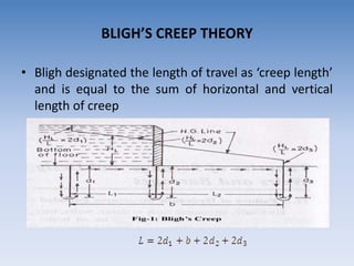
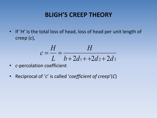
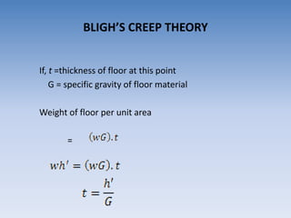
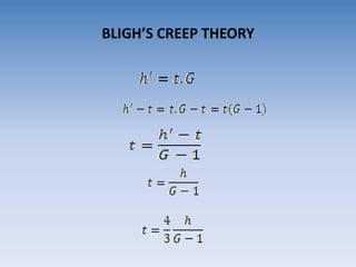
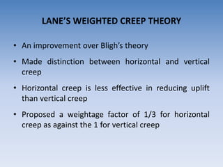
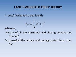
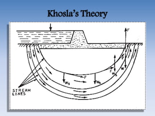
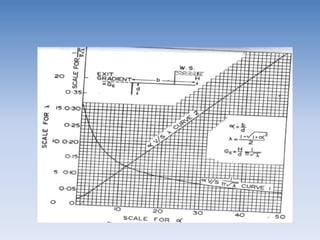
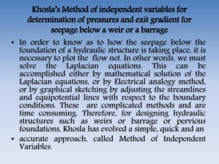
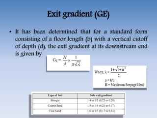
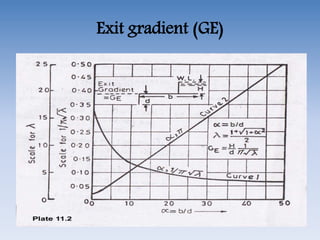
SlideShare a Scribd company logo
Design of Impervious Floor
DIVYA VISHNOI
Assistant Professor
DESIGN OF IMPERVIOUS FLOOR FOR
SUBSURFACE FLOW
• Bligh’s creep theory
• Khosla’s theory
BLIGH’S CREEP THEORY
• In 1910 W.G. Bligh presented a theory for the subsurface
flow in his book “Practical Design of Irrigation Work. This
theory is known as Bligh’s theory.
• Design of impervious floor or apron
– Directly depend on the possibilities of percolation in
the porous soil on which the apron is built
BLIGH’S CREEP THEORY
• Bligh assumed that
– Hydraulic gradient is constant throughout the
impervious length of the apron
– The percolating water creeps along the contact of base
profile of the apron with the sub-soil, losing head
enroute, proportional to the length of its travel
– Stoppage of percolation by cut off (pile) possible only if
it extends up to impermeable soil strata
• Bligh designated the length of travel as ‘creep length’
and is equal to the sum of horizontal and vertical
length of creep
BLIGH’S CREEP THEORY
• If ‘H’ is the total loss of head, loss of head per unit length of
creep (c),
• c-percolation coefficient
• Reciprocal of ‘c’ is called ‘coefficient of creep’(C)
BLIGH’S CREEP THEORY
321 222 dddb
H
L
H
c


• Design criteria
(i) Safety against piping
Length of creep should be sufficient to provide a safe
hydraulic gradient according to the type of soil
Thus, safe creep length,
Where, C= creep coefficient=1/c
BLIGH’S CREEP THEORY
• Design criteria
(ii) Safety against uplift pressure
Let ‘h’’ be the uplift pressure head at any point of
the apron
The uplift pressure = wh’
This uplift pressure is balanced by the weight of the
floor at this point
BLIGH’S CREEP THEORY
If, t =thickness of floor at this point
G = specific gravity of floor material
Weight of floor per unit area
=
BLIGH’S CREEP THEORY
LIMITATIONS OF BLIGH’S THEORY
• Bligh made no distinction between horizontal and vertical
creep
• Did not explain the idea of exit gradient - safety against
undermining cannot simply be obtained by considering a
flat average gradient but by keeping this gradient will be
low critical
• No distinction between outer and inner faces of sheet
piles or the intermediate sheet piles, whereas from
investigation it is clear, that the outer faces of the end
sheet piles are much more effective than inner ones
• Losses of head does not take place in the same
proportions as the creep length. Also the uplift
pressure distribution is not linear but follow a sine
curve
• Bligh did not specify the absolute necessity of
providing a cutoff at the d/s end of the floor,
whereas it is absolutely essential to provide a deep
vertical cutoff at the d/s end of the floor to prevent
undermining.
LIMITATIONS OF BLIGH’S THEORY
LANE’S WEIGHTED CREEP THEORY
• An improvement over Bligh’s theory
• Made distinction between horizontal and vertical
creep
• Horizontal creep is less effective in reducing uplift
than vertical creep
• Proposed a weightage factor of 1/3 for horizontal
creep as against the 1 for vertical creep
LANE’S WEIGHTED CREEP THEORY
• Lane’s Weighted creep length
Whereas,
N=sum of all the horizontal and sloping contact less
than 45°
V=sum of all the vertical and sloping contact less than
45°
VNLw 
3
1
LANE’S WEIGHTED CREEP THEORY
Drawbacks of the Lane’s weighted theory
Most of limitations same as Bligh’s theory.
It is empirical and lacks any rational basis.
Only theoretically important.
LANE’S WEIGHTED CREEP THEORY
Khosla’s Theory
• Khosla’s Theory and Concept of Flow Nets
• Many of the important hydraulic structures,
such as weirs and barrage, were designed on the
basis of Bligh’s theory between the periods 1910
to 1925. In 1926 – 27, the upper Chenab canal
siphons, designed on Bligh’s theory, started
posing undermining troubles. Investigations
started. During investigations, the actual pressure
measurement were made with the help of pipe
inserted in the floors of these siphons, which
indicated the actual pressures are quite different
from those computed on the basis of Bligh’s
theory.
• Khosla’s theory. The main principles of this theory are
summarized below:
• (a) The seepage water does not creep along the
bottom contour of pucca flood as started by Bligh,
but on the other hand, this water moves along a set
of stream-lines. This steady seepage in a vertical
plane for a homogeneous soil can be expressed by
Laplacian equation:
0
Khosla’s Theory
• The equation represents two sets of curves
intersecting each other orthogonally. The resultant
flow diagram showing both of the curves is called a
Flow Net.
• Stream Lines: The streamlines represent the paths
along which the water flows through the sub-soil.
• Every particle entering the soil at a given point
upstream of the work, will trace out its own path and
will represent a streamline. The first streamline
follows the bottom contour of the works and is the
same as Bligh’s path of creep. The remaining
streamlines follows smooth curves transiting slowly
from the outline of the foundation to a semi-ellipse, as
Khosla’s Theory
• Equipotential Lines: Treating the downstream bed as
datum and assuming no water on the downstream
side, it can be easily started that every streamline
possesses a head equal to h1 while entering the soil;
and when it emerges at the down-stream end into the
atmosphere, its head is zero. Thus, the head h1 is
entirely lost during the passage of water along the
streamlines.
Khosla’s Theory
• Further, at every intermediate point in its path,
there is certain residual head (h) still to be dissipated
in the remaining length to be traversed to the
downstream end. This fact is applicable to every
streamline, and hence, there will be points on
different streamlines having the same value of
residual head h. If such points are joined together,
the curve obtained is called an equipotential line.
Khosla’s Theory
Khosla’s Theory
Every water particle on line AB is having a
residual head h = h1, and on CD is having a
residual head h = 0, and hence, AB and CD
are equipotential lines.
Since an equipotential line represent the
joining of points of equal residual head, hence
if piezometers were installed on an
equipotential line, the water will rise in all of
them up to the same level as shown in figure
below
Khosla’s Theory
Khosla’s Theory
• The seepage water exerts a force at each point in the
direction of flow and tangential to the streamlines as
shown in figure above. This force (F) has an upward
component from the point where the streamlines turns
upward. For soil grains to remain stable, the upward
component of this force should be counterbalanced by
the submerged weight of the soil grain. This force has
the maximum disturbing tendency at the exit end,
because the direction of this force at the exit point is
vertically upward, and hence full force acts as its
upward component.
Khosla’s Theory
• For the soil grain to remain stable, the
submerged weight of soil grain should be more
than this upward disturbing force. The
disturbing force at any point is proportional to
the gradient of pressure of water at that point
(i.e. dp/dt). This gradient of pressure of water at
the exit end is called the exit gradient. In order
that the soil particles at exit remain stable, the
upward pressure at exit should be safe. In other
words, the exit gradient should be safe.
Critical Exit Gradient
• This exit gradient is said to be critical, when
the upward disturbing force on the grain is
just equal to the submerged weight of the
grain at the exit. When a factor of safety equal
to 4 to 5 is used, the exit gradient can then be
taken as safe. In other words, an exit gradient
equal to ¼ to 1/5 of the critical exit gradient
ensured, so as to keep the structure safe
against piping.
• The submerged weight (Ws) of a unit volume
of soil is given as:
Critical Exit Gradient
KHOSLA’S THEORY
• Dr. A. N. Khosla and his associates done
investigations on structures designed based on
Bligh’s theory and following conclusions were made
– The outer faces of sheet piles are much more
effective than inner ones and the horizontal length
of floor
– The intermediate sheet piles, if smaller in length
than the outer ones were ineffective
– Undermining of floors started from the tail end. If
hydraulic gradient at exit is more than the critical
gradient, soil particles will move with water and
leads to failure
– It is absolutely essential to have reasonably deep
vertical cutoff at the d/s end to prevent
undermining
KHOSLA’S THEORY
• Khosla and his associates carried out further research
to find out a solution to the problem of subsurface
flow and provided a solution
– Khosla’s theory
– Considered the flow pattern below the impervious
base of hydraulic structures on pervious
foundations to find the distribution of uplift
pressure on the base of the structure and the exit
gradient
KHOSLA’S THEORY
KHOSLA’S METHOD OF INDEPENDENT
VARIABLES
• A composite weir section is split up into a number of
simple standard forms
• The standard forms
(a) A straight horizontal floor of negligible thickness with a
sheet pile either at the u/s end or at the d/s end of the
floor
(b) A straight horizontal floor of negligible thickness with
a sheet pile at some intermediate point
(c) A straight horizontal floor depressed below the bed
but with no vertical cutoff
KHOSLA’S METHOD OF INDEPENDENT
VARIABLES
• These standard cases were analyzed by Khosla and
his associates and expressions were derived for
determining
– The residual seepage head (uplift pressure) at key points
(key points are the junction points of pile and floor, bottom
point of pile and bottom corners of depressed floor)
– Exit gradient
– These results are presented in the form of curves
KHOSLA’S METHOD OF INDEPENDENT
VARIABLES
KHOSLA’S METHOD OF INDEPENDENT
VARIABLES
• The curves gives the values of Φ (the ratio of residual
seepage head and total seepage head) at key points
• The directions for reading the curves are given on
the curves itself
Khosla’s Method of independent variables for
determination of pressures and exit gradient for
seepage below a weir or a barrage
• In this method, a complex profile like that of a weir is
broken into a number of simple profiles; each of
which can be solved mathematically. profiles which
are most useful are:
• (i) A straight horizontal floor of negligible thickness
with a sheet pile line on the u/s end and d/s end.
• (ii) A straight horizontal floor depressed below the bed
but without any vertical cut-offs.
• (iii) A straight horizontal floor of negligible thickness
with a sheet pile line at some intermediate point.
Khosla’s Method of independent variables for
determination of pressures and exit gradient for
seepage below a weir or a barrage
• The key points are the junctions of the floor and the
pole lines on either side, and the bottom point of
• the pile line, and the bottom corners in the case of a
depressed floor. The percentage pressures at these key
• points for the simple forms into which the complex
profile has been broken is valid for the complex
profile
• itself, if corrected for
• (a) Correction for the thickness of floor
• (b) Correction for the Mutual interference of Piles
• (c) Correction for the slope of the floor
• (i) Straight floor of negligible thickness with pile at u/s end
• (ii) Straight floor of negligible thickness with pile at some
intermediate point
• (iii) Straight floor of negligible thickness with pile at d/s end
• The pressure obtained at the key points from curves are then
corrected for
• (i) Thickness of floor
• (ii) Interference of piles
• (iii) Sloping floor
CORRECTION FOR THICKNESS OF FLOOR
• Pressure at actual points C1 and E1 can be computed by
considering linear variation of pressure between point D
and points E and C
• When pile is at u/s end,
• Correction for
• Pressure at
• For the intermediate pile,
• Correction for
• Pressure at
• Correction for
• Pressure at
CORRECTION FOR THICKNESS OF FLOOR
• When pile at d/s end,
• Correction for
• Pressure at
CORRECTION FOR THICKNESS OF FLOOR
(b) Correction for the Mutual interference of
Piles
The correction C to be applied as percentage of head due to this effect, is given
by
Where,
b′ = The distance between two pile lines.
D = The depth of the pile line, the influence of which has to be determined on
the neighboring pile of depth d. D is to be measured below the level at
which interference is desired.
d = The depth of the pile on which the effect is considered
b = Total floor length
The correction is positive for the points in the rear of back water, and
subtractive for the points forward in the direction of flow. This equation
does not apply to the effect of an outer pile on an intermediate pile, if the
intermediate pile is equal to or smaller than the outer pile and is at a
distance less than twice the length of the outer pile.
(b) Correction for the Mutual interference of
Piles
(b) Correction for the Mutual interference of Piles
(b) Correction for the Mutual interference of
Piles
• Suppose in the above figure, we are considering the influence of
the pile no (2) on pile no (1) for correcting the pressure at C1.
Since the point C1 is in the rear, this correction shall be positive.
While the correction to be applied to E2 due to pile no (1)
shall be negative, since the point E2 is in the forward direction
of flow. Similarly, the correction at C2 due to pile no (3) is
positive and the correction at E2 due to pile no (2) is negative.
CORRECTION FOR SLOPE
• The % pressure under a floor sloping down is greater than
that under a horizontal floor
• The % pressure under a floor sloping up is less than that
under a horizontal floor
• Correction is plus for down slopes and minus for up slopes
Slope (vertical/horizontal) Correction (%)
1 in 1 11.2
1 in 2 6.5
1 in 3 4.5
1 in 4 3.3
1 in 5 2.8
1 in 6 2.5
1 in 7 2.3
1 in 8 2.0
• The corrections given table are to be further multiplied by the
proportion of horizontal length of slope to the distance
between the two pile lines in between which the sloping floor
is located
• The slope correction is applicable only to that key points of
pile line which is fixed at the beginning or end of the slope
CORRECTION FOR SLOPE
Khosla’s Method of independent variables for
determination of pressures and exit gradient for
seepage below a weir or a barrage
• In order to know as to how the seepage below the
foundation of a hydraulic structure is taking place, it is
necessary to plot the flow net. In other words, we must
solve the Laplacian equations. This can be
accomplished either by mathematical solution of the
Laplacian equations, or by Electrical analogy method,
or by graphical sketching by adjusting the streamlines
and equipotential lines with respect to the boundary
conditions. These are complicated methods and are
time consuming. Therefore, for designing hydraulic
structures such as weirs or barrage or pervious
foundations, Khosla has evolved a simple, quick and an
• accurate approach, called Method of Independent
Variables.
Exit gradient (GE)
• It has been determined that for a standard form
consisting of a floor length (b) with a vertical cutoff
of depth (d), the exit gradient at its downstream end
is given by
Exit gradient (GE)
RTU Questions
• Explain Khosla’s method of independent variables?
• Discuss Bligh’s theory with its limitations?
• Explain Bligh’s Creep Theory in details?
• Compare Khosla and Bligh’s theory?
• Write down the expression for uplift pressure at the
salient point E, D and C of pile at upstream,
downstream and intermediate pile. What is the
effect of mutual interference of piles?
• Describe the exit gradient and critical gradients and
their importance?
References
• Irrigation Engineering & Water Power Engineering
– By Prof. P.N.MODI and Dr. S.M. SETH
--- Standard Book House Delhi
• Irrigation Engineering & Hydraulic Structures
– By Prof. Santosh Kumar Garg
– Khanna Publishers
• Irrigation, Water Power Engineering & Hydraulic Structures
– By Prof K.R. Arora
– Standard Publishers Distributions
• Internet Websites
• http://www.aboutcivil.org/
• http://nptel.ac.in/courses/105105110/
Thanks
GHT

More Related Content

What's hot

Cross Drainage Works
Cross Drainage WorksCross Drainage Works
Cross Drainage Works
GAURAV. H .TANDON
 
Weirs on Permeable Foundations
Weirs on Permeable FoundationsWeirs on Permeable Foundations
Weirs on Permeable Foundations
Malla Reddy University
 
Khosla theory
Khosla theoryKhosla theory
Khosla theory
AparnaRath
 
Canal regulation works. m4pptx
Canal regulation works. m4pptxCanal regulation works. m4pptx
Canal regulation works. m4pptx
Bibhabasu Mohanty
 
Storage head works
Storage head worksStorage head works
Storage head works
Anirudhan K M
 
weir & barrage
weir & barrageweir & barrage
weir & barrage
Raj Daxini
 
Spillway and its types
Spillway and its typesSpillway and its types
Spillway and its types
Bilal Mirani
 
Spillway
Spillway Spillway
Spillway
Naval Bandawar
 
Spillways
SpillwaysSpillways
Gravity Dam
Gravity DamGravity Dam
Weir and barrage lecture
Weir and barrage lectureWeir and barrage lecture
Weir and barrage lecture
sarhad university peshawer
 
Canal falls and its classification
Canal falls and its classificationCanal falls and its classification
Canal falls and its classification
GNANA PRAKASH
 
Canal alignment
Canal alignmentCanal alignment
Canal alignment
Naveenaa
 
river training work
river training workriver training work
river training work
Vishal Chaudhari
 
Cross drainage work
Cross drainage workCross drainage work
Cross drainage work
Divya Vishnoi
 
Spillways components and types
Spillways components and typesSpillways components and types
Spillways components and types
Rajkumar G
 
theory of seepage
theory of seepagetheory of seepage
theory of seepage
SANJEEV Wazir
 
presentation : cross drainage work
presentation : cross drainage workpresentation : cross drainage work
presentation : cross drainage work
Eddy Ankit Gangani
 
Types of earth dams
Types of earth damsTypes of earth dams
Types of earth dams
saibabu48
 
Hydraulic jump
Hydraulic jumpHydraulic jump
Hydraulic jump
Venkata Sai Kari
 

What's hot (20)

Cross Drainage Works
Cross Drainage WorksCross Drainage Works
Cross Drainage Works
 
Weirs on Permeable Foundations
Weirs on Permeable FoundationsWeirs on Permeable Foundations
Weirs on Permeable Foundations
 
Khosla theory
Khosla theoryKhosla theory
Khosla theory
 
Canal regulation works. m4pptx
Canal regulation works. m4pptxCanal regulation works. m4pptx
Canal regulation works. m4pptx
 
Storage head works
Storage head worksStorage head works
Storage head works
 
weir & barrage
weir & barrageweir & barrage
weir & barrage
 
Spillway and its types
Spillway and its typesSpillway and its types
Spillway and its types
 
Spillway
Spillway Spillway
Spillway
 
Spillways
SpillwaysSpillways
Spillways
 
Gravity Dam
Gravity DamGravity Dam
Gravity Dam
 
Weir and barrage lecture
Weir and barrage lectureWeir and barrage lecture
Weir and barrage lecture
 
Canal falls and its classification
Canal falls and its classificationCanal falls and its classification
Canal falls and its classification
 
Canal alignment
Canal alignmentCanal alignment
Canal alignment
 
river training work
river training workriver training work
river training work
 
Cross drainage work
Cross drainage workCross drainage work
Cross drainage work
 
Spillways components and types
Spillways components and typesSpillways components and types
Spillways components and types
 
theory of seepage
theory of seepagetheory of seepage
theory of seepage
 
presentation : cross drainage work
presentation : cross drainage workpresentation : cross drainage work
presentation : cross drainage work
 
Types of earth dams
Types of earth damsTypes of earth dams
Types of earth dams
 
Hydraulic jump
Hydraulic jumpHydraulic jump
Hydraulic jump
 

Similar to Theory for impervious floor

Diversionheadworks
DiversionheadworksDiversionheadworks
Diversionheadworks
saibabu48
 
Diversion head works ajitha miss
Diversion head works ajitha missDiversion head works ajitha miss
Diversion head works ajitha miss
SHAMJITH KM
 
diversionheadworksajithamiss-140806045330-phpapp02.ppt
diversionheadworksajithamiss-140806045330-phpapp02.pptdiversionheadworksajithamiss-140806045330-phpapp02.ppt
diversionheadworksajithamiss-140806045330-phpapp02.ppt
Ayushsharma131736
 
SEEPAGE ANALYSIS & FLOWNETS.pdf
SEEPAGE ANALYSIS & FLOWNETS.pdfSEEPAGE ANALYSIS & FLOWNETS.pdf
SEEPAGE ANALYSIS & FLOWNETS.pdf
GourhariBiswas1
 
Chapter 4 seepage theories
Chapter 4 seepage theoriesChapter 4 seepage theories
Chapter 4 seepage theories
Mohsin Siddique
 
Design of Hydraulic Structures and Cross Drainage Works
Design of Hydraulic Structures and Cross Drainage WorksDesign of Hydraulic Structures and Cross Drainage Works
Design of Hydraulic Structures and Cross Drainage Works
ArunSekhar18
 
Irrigation Engineering Terms In Civil Engineering
Irrigation Engineering Terms In Civil EngineeringIrrigation Engineering Terms In Civil Engineering
Irrigation Engineering Terms In Civil Engineering
Latif Hyder Wadho
 
ME-438 Aerodynamics (week 9)
ME-438 Aerodynamics (week 9)ME-438 Aerodynamics (week 9)
ME-438 Aerodynamics (week 9)
Dr. Bilal Siddiqui, C.Eng., MIMechE, FRAeS
 
Permeability of Soils & Seepage Analysis
Permeability of Soils & Seepage AnalysisPermeability of Soils & Seepage Analysis
Permeability of Soils & Seepage Analysis
wasim shaikh
 
FIXED BED FLUIDIZATION.pptx
FIXED BED FLUIDIZATION.pptxFIXED BED FLUIDIZATION.pptx
FIXED BED FLUIDIZATION.pptx
ParaDise11
 
design of weirs
design of weirsdesign of weirs
design of weirs
SANJEEV Wazir
 
Vivek kumar
Vivek kumarVivek kumar
Vivek kumar
vk805186
 
Vivek kumar
Vivek kumarVivek kumar
Vivek kumar
vk805186
 
Hydraulics chapter 1
Hydraulics chapter 1Hydraulics chapter 1
Hydraulics chapter 1
Kashif Hashmi
 
Chapter 4 Hydraulic Characteristics of Soil.pdf
Chapter 4  Hydraulic Characteristics of Soil.pdfChapter 4  Hydraulic Characteristics of Soil.pdf
Chapter 4 Hydraulic Characteristics of Soil.pdf
matiozil2436
 
shaft.pptx
shaft.pptxshaft.pptx
shaft.pptx
tameneaDemissie
 
Spillways and Diversion Headwork's
Spillways and Diversion Headwork'sSpillways and Diversion Headwork's
Spillways and Diversion Headwork's
kartikchourasia
 
Groundwater hydrology
Groundwater hydrologyGroundwater hydrology
Groundwater hydrology
VijithaVikneshwaran
 
Flow through nozzel_AMIT
Flow through nozzel_AMITFlow through nozzel_AMIT
Flow through nozzel_AMITAmit Sharma
 

Similar to Theory for impervious floor (20)

Diversionheadworks
DiversionheadworksDiversionheadworks
Diversionheadworks
 
Diversion head works ajitha miss
Diversion head works ajitha missDiversion head works ajitha miss
Diversion head works ajitha miss
 
diversionheadworksajithamiss-140806045330-phpapp02.ppt
diversionheadworksajithamiss-140806045330-phpapp02.pptdiversionheadworksajithamiss-140806045330-phpapp02.ppt
diversionheadworksajithamiss-140806045330-phpapp02.ppt
 
SEEPAGE ANALYSIS & FLOWNETS.pdf
SEEPAGE ANALYSIS & FLOWNETS.pdfSEEPAGE ANALYSIS & FLOWNETS.pdf
SEEPAGE ANALYSIS & FLOWNETS.pdf
 
Chapter 4 seepage theories
Chapter 4 seepage theoriesChapter 4 seepage theories
Chapter 4 seepage theories
 
Design of Hydraulic Structures and Cross Drainage Works
Design of Hydraulic Structures and Cross Drainage WorksDesign of Hydraulic Structures and Cross Drainage Works
Design of Hydraulic Structures and Cross Drainage Works
 
Irrigation Engineering Terms In Civil Engineering
Irrigation Engineering Terms In Civil EngineeringIrrigation Engineering Terms In Civil Engineering
Irrigation Engineering Terms In Civil Engineering
 
ME-438 Aerodynamics (week 9)
ME-438 Aerodynamics (week 9)ME-438 Aerodynamics (week 9)
ME-438 Aerodynamics (week 9)
 
Permeability of Soils & Seepage Analysis
Permeability of Soils & Seepage AnalysisPermeability of Soils & Seepage Analysis
Permeability of Soils & Seepage Analysis
 
FIXED BED FLUIDIZATION.pptx
FIXED BED FLUIDIZATION.pptxFIXED BED FLUIDIZATION.pptx
FIXED BED FLUIDIZATION.pptx
 
design of weirs
design of weirsdesign of weirs
design of weirs
 
Vivek kumar
Vivek kumarVivek kumar
Vivek kumar
 
Vivek kumar
Vivek kumarVivek kumar
Vivek kumar
 
Notches
NotchesNotches
Notches
 
Hydraulics chapter 1
Hydraulics chapter 1Hydraulics chapter 1
Hydraulics chapter 1
 
Chapter 4 Hydraulic Characteristics of Soil.pdf
Chapter 4  Hydraulic Characteristics of Soil.pdfChapter 4  Hydraulic Characteristics of Soil.pdf
Chapter 4 Hydraulic Characteristics of Soil.pdf
 
shaft.pptx
shaft.pptxshaft.pptx
shaft.pptx
 
Spillways and Diversion Headwork's
Spillways and Diversion Headwork'sSpillways and Diversion Headwork's
Spillways and Diversion Headwork's
 
Groundwater hydrology
Groundwater hydrologyGroundwater hydrology
Groundwater hydrology
 
Flow through nozzel_AMIT
Flow through nozzel_AMITFlow through nozzel_AMIT
Flow through nozzel_AMIT
 

More from Divya Vishnoi

Understanding of Disasters
Understanding of DisastersUnderstanding of Disasters
Understanding of Disasters
Divya Vishnoi
 
Expansion joints in bridge
Expansion joints in bridgeExpansion joints in bridge
Expansion joints in bridge
Divya Vishnoi
 
Hydropower
HydropowerHydropower
Hydropower
Divya Vishnoi
 
Spillways
SpillwaysSpillways
Spillways
Divya Vishnoi
 
Failures of an earthen dam
Failures of an earthen damFailures of an earthen dam
Failures of an earthen dam
Divya Vishnoi
 
Force acting on gravity dam
Force acting on gravity damForce acting on gravity dam
Force acting on gravity dam
Divya Vishnoi
 
Gravity dam stability analysis
Gravity dam stability analysisGravity dam stability analysis
Gravity dam stability analysis
Divya Vishnoi
 
Failure of weir and barrage
Failure of weir and barrageFailure of weir and barrage
Failure of weir and barrage
Divya Vishnoi
 
Diversion head work
Diversion head workDiversion head work
Diversion head work
Divya Vishnoi
 
Building foundation
Building foundationBuilding foundation
Building foundation
Divya Vishnoi
 
Temporary structures
Temporary structuresTemporary structures
Temporary structures
Divya Vishnoi
 
Damp proof course
Damp proof courseDamp proof course
Damp proof course
Divya Vishnoi
 
Roof and roof covering
Roof and roof coveringRoof and roof covering
Roof and roof covering
Divya Vishnoi
 
Ground and upper floor
Ground and upper floorGround and upper floor
Ground and upper floor
Divya Vishnoi
 
Mortar plaster pointing
Mortar plaster pointingMortar plaster pointing
Mortar plaster pointing
Divya Vishnoi
 
Precast construction
Precast constructionPrecast construction
Precast construction
Divya Vishnoi
 
Brick masonry and stone masonry
Brick masonry and stone masonryBrick masonry and stone masonry
Brick masonry and stone masonry
Divya Vishnoi
 
Prefabrication construction
Prefabrication constructionPrefabrication construction
Prefabrication construction
Divya Vishnoi
 
Tension coefficient method
Tension coefficient methodTension coefficient method
Tension coefficient method
Divya Vishnoi
 
IS 13827
IS 13827IS 13827
IS 13827
Divya Vishnoi
 

More from Divya Vishnoi (20)

Understanding of Disasters
Understanding of DisastersUnderstanding of Disasters
Understanding of Disasters
 
Expansion joints in bridge
Expansion joints in bridgeExpansion joints in bridge
Expansion joints in bridge
 
Hydropower
HydropowerHydropower
Hydropower
 
Spillways
SpillwaysSpillways
Spillways
 
Failures of an earthen dam
Failures of an earthen damFailures of an earthen dam
Failures of an earthen dam
 
Force acting on gravity dam
Force acting on gravity damForce acting on gravity dam
Force acting on gravity dam
 
Gravity dam stability analysis
Gravity dam stability analysisGravity dam stability analysis
Gravity dam stability analysis
 
Failure of weir and barrage
Failure of weir and barrageFailure of weir and barrage
Failure of weir and barrage
 
Diversion head work
Diversion head workDiversion head work
Diversion head work
 
Building foundation
Building foundationBuilding foundation
Building foundation
 
Temporary structures
Temporary structuresTemporary structures
Temporary structures
 
Damp proof course
Damp proof courseDamp proof course
Damp proof course
 
Roof and roof covering
Roof and roof coveringRoof and roof covering
Roof and roof covering
 
Ground and upper floor
Ground and upper floorGround and upper floor
Ground and upper floor
 
Mortar plaster pointing
Mortar plaster pointingMortar plaster pointing
Mortar plaster pointing
 
Precast construction
Precast constructionPrecast construction
Precast construction
 
Brick masonry and stone masonry
Brick masonry and stone masonryBrick masonry and stone masonry
Brick masonry and stone masonry
 
Prefabrication construction
Prefabrication constructionPrefabrication construction
Prefabrication construction
 
Tension coefficient method
Tension coefficient methodTension coefficient method
Tension coefficient method
 
IS 13827
IS 13827IS 13827
IS 13827
 

Recently uploaded

在线办理(ANU毕业证书)澳洲国立大学毕业证录取通知书一模一样
在线办理(ANU毕业证书)澳洲国立大学毕业证录取通知书一模一样在线办理(ANU毕业证书)澳洲国立大学毕业证录取通知书一模一样
在线办理(ANU毕业证书)澳洲国立大学毕业证录取通知书一模一样
obonagu
 
The role of big data in decision making.
The role of big data in decision making.The role of big data in decision making.
The role of big data in decision making.
ankuprajapati0525
 
Governing Equations for Fundamental Aerodynamics_Anderson2010.pdf
Governing Equations for Fundamental Aerodynamics_Anderson2010.pdfGoverning Equations for Fundamental Aerodynamics_Anderson2010.pdf
Governing Equations for Fundamental Aerodynamics_Anderson2010.pdf
WENKENLI1
 
Industrial Training at Shahjalal Fertilizer Company Limited (SFCL)
Industrial Training at Shahjalal Fertilizer Company Limited (SFCL)Industrial Training at Shahjalal Fertilizer Company Limited (SFCL)
Industrial Training at Shahjalal Fertilizer Company Limited (SFCL)
MdTanvirMahtab2
 
block diagram and signal flow graph representation
block diagram and signal flow graph representationblock diagram and signal flow graph representation
block diagram and signal flow graph representation
Divya Somashekar
 
一比一原版(IIT毕业证)伊利诺伊理工大学毕业证成绩单专业办理
一比一原版(IIT毕业证)伊利诺伊理工大学毕业证成绩单专业办理一比一原版(IIT毕业证)伊利诺伊理工大学毕业证成绩单专业办理
一比一原版(IIT毕业证)伊利诺伊理工大学毕业证成绩单专业办理
zwunae
 
MCQ Soil mechanics questions (Soil shear strength).pdf
MCQ Soil mechanics questions (Soil shear strength).pdfMCQ Soil mechanics questions (Soil shear strength).pdf
MCQ Soil mechanics questions (Soil shear strength).pdf
Osamah Alsalih
 
DESIGN A COTTON SEED SEPARATION MACHINE.docx
DESIGN A COTTON SEED SEPARATION MACHINE.docxDESIGN A COTTON SEED SEPARATION MACHINE.docx
DESIGN A COTTON SEED SEPARATION MACHINE.docx
FluxPrime1
 
Cosmetic shop management system project report.pdf
Cosmetic shop management system project report.pdfCosmetic shop management system project report.pdf
Cosmetic shop management system project report.pdf
Kamal Acharya
 
Railway Signalling Principles Edition 3.pdf
Railway Signalling Principles Edition 3.pdfRailway Signalling Principles Edition 3.pdf
Railway Signalling Principles Edition 3.pdf
TeeVichai
 
AP LAB PPT.pdf ap lab ppt no title specific
AP LAB PPT.pdf ap lab ppt no title specificAP LAB PPT.pdf ap lab ppt no title specific
AP LAB PPT.pdf ap lab ppt no title specific
BrazilAccount1
 
Architectural Portfolio Sean Lockwood
Architectural Portfolio Sean LockwoodArchitectural Portfolio Sean Lockwood
Architectural Portfolio Sean Lockwood
seandesed
 
ethical hacking-mobile hacking methods.ppt
ethical hacking-mobile hacking methods.pptethical hacking-mobile hacking methods.ppt
ethical hacking-mobile hacking methods.ppt
Jayaprasanna4
 
road safety engineering r s e unit 3.pdf
road safety engineering  r s e unit 3.pdfroad safety engineering  r s e unit 3.pdf
road safety engineering r s e unit 3.pdf
VENKATESHvenky89705
 
weather web application report.pdf
weather web application report.pdfweather web application report.pdf
weather web application report.pdf
Pratik Pawar
 
English lab ppt no titlespecENG PPTt.pdf
English lab ppt no titlespecENG PPTt.pdfEnglish lab ppt no titlespecENG PPTt.pdf
English lab ppt no titlespecENG PPTt.pdf
BrazilAccount1
 
Student information management system project report ii.pdf
Student information management system project report ii.pdfStudent information management system project report ii.pdf
Student information management system project report ii.pdf
Kamal Acharya
 
Gen AI Study Jams _ For the GDSC Leads in India.pdf
Gen AI Study Jams _ For the GDSC Leads in India.pdfGen AI Study Jams _ For the GDSC Leads in India.pdf
Gen AI Study Jams _ For the GDSC Leads in India.pdf
gdsczhcet
 
ML for identifying fraud using open blockchain data.pptx
ML for identifying fraud using open blockchain data.pptxML for identifying fraud using open blockchain data.pptx
ML for identifying fraud using open blockchain data.pptx
Vijay Dialani, PhD
 
H.Seo, ICLR 2024, MLILAB, KAIST AI.pdf
H.Seo,  ICLR 2024, MLILAB,  KAIST AI.pdfH.Seo,  ICLR 2024, MLILAB,  KAIST AI.pdf
H.Seo, ICLR 2024, MLILAB, KAIST AI.pdf
MLILAB
 

Recently uploaded (20)

在线办理(ANU毕业证书)澳洲国立大学毕业证录取通知书一模一样
在线办理(ANU毕业证书)澳洲国立大学毕业证录取通知书一模一样在线办理(ANU毕业证书)澳洲国立大学毕业证录取通知书一模一样
在线办理(ANU毕业证书)澳洲国立大学毕业证录取通知书一模一样
 
The role of big data in decision making.
The role of big data in decision making.The role of big data in decision making.
The role of big data in decision making.
 
Governing Equations for Fundamental Aerodynamics_Anderson2010.pdf
Governing Equations for Fundamental Aerodynamics_Anderson2010.pdfGoverning Equations for Fundamental Aerodynamics_Anderson2010.pdf
Governing Equations for Fundamental Aerodynamics_Anderson2010.pdf
 
Industrial Training at Shahjalal Fertilizer Company Limited (SFCL)
Industrial Training at Shahjalal Fertilizer Company Limited (SFCL)Industrial Training at Shahjalal Fertilizer Company Limited (SFCL)
Industrial Training at Shahjalal Fertilizer Company Limited (SFCL)
 
block diagram and signal flow graph representation
block diagram and signal flow graph representationblock diagram and signal flow graph representation
block diagram and signal flow graph representation
 
一比一原版(IIT毕业证)伊利诺伊理工大学毕业证成绩单专业办理
一比一原版(IIT毕业证)伊利诺伊理工大学毕业证成绩单专业办理一比一原版(IIT毕业证)伊利诺伊理工大学毕业证成绩单专业办理
一比一原版(IIT毕业证)伊利诺伊理工大学毕业证成绩单专业办理
 
MCQ Soil mechanics questions (Soil shear strength).pdf
MCQ Soil mechanics questions (Soil shear strength).pdfMCQ Soil mechanics questions (Soil shear strength).pdf
MCQ Soil mechanics questions (Soil shear strength).pdf
 
DESIGN A COTTON SEED SEPARATION MACHINE.docx
DESIGN A COTTON SEED SEPARATION MACHINE.docxDESIGN A COTTON SEED SEPARATION MACHINE.docx
DESIGN A COTTON SEED SEPARATION MACHINE.docx
 
Cosmetic shop management system project report.pdf
Cosmetic shop management system project report.pdfCosmetic shop management system project report.pdf
Cosmetic shop management system project report.pdf
 
Railway Signalling Principles Edition 3.pdf
Railway Signalling Principles Edition 3.pdfRailway Signalling Principles Edition 3.pdf
Railway Signalling Principles Edition 3.pdf
 
AP LAB PPT.pdf ap lab ppt no title specific
AP LAB PPT.pdf ap lab ppt no title specificAP LAB PPT.pdf ap lab ppt no title specific
AP LAB PPT.pdf ap lab ppt no title specific
 
Architectural Portfolio Sean Lockwood
Architectural Portfolio Sean LockwoodArchitectural Portfolio Sean Lockwood
Architectural Portfolio Sean Lockwood
 
ethical hacking-mobile hacking methods.ppt
ethical hacking-mobile hacking methods.pptethical hacking-mobile hacking methods.ppt
ethical hacking-mobile hacking methods.ppt
 
road safety engineering r s e unit 3.pdf
road safety engineering  r s e unit 3.pdfroad safety engineering  r s e unit 3.pdf
road safety engineering r s e unit 3.pdf
 
weather web application report.pdf
weather web application report.pdfweather web application report.pdf
weather web application report.pdf
 
English lab ppt no titlespecENG PPTt.pdf
English lab ppt no titlespecENG PPTt.pdfEnglish lab ppt no titlespecENG PPTt.pdf
English lab ppt no titlespecENG PPTt.pdf
 
Student information management system project report ii.pdf
Student information management system project report ii.pdfStudent information management system project report ii.pdf
Student information management system project report ii.pdf
 
Gen AI Study Jams _ For the GDSC Leads in India.pdf
Gen AI Study Jams _ For the GDSC Leads in India.pdfGen AI Study Jams _ For the GDSC Leads in India.pdf
Gen AI Study Jams _ For the GDSC Leads in India.pdf
 
ML for identifying fraud using open blockchain data.pptx
ML for identifying fraud using open blockchain data.pptxML for identifying fraud using open blockchain data.pptx
ML for identifying fraud using open blockchain data.pptx
 
H.Seo, ICLR 2024, MLILAB, KAIST AI.pdf
H.Seo,  ICLR 2024, MLILAB,  KAIST AI.pdfH.Seo,  ICLR 2024, MLILAB,  KAIST AI.pdf
H.Seo, ICLR 2024, MLILAB, KAIST AI.pdf
 

Theory for impervious floor

  • 1. Design of Impervious Floor DIVYA VISHNOI Assistant Professor
  • 2. DESIGN OF IMPERVIOUS FLOOR FOR SUBSURFACE FLOW • Bligh’s creep theory • Khosla’s theory
  • 3. BLIGH’S CREEP THEORY • In 1910 W.G. Bligh presented a theory for the subsurface flow in his book “Practical Design of Irrigation Work. This theory is known as Bligh’s theory. • Design of impervious floor or apron – Directly depend on the possibilities of percolation in the porous soil on which the apron is built
  • 4. BLIGH’S CREEP THEORY • Bligh assumed that – Hydraulic gradient is constant throughout the impervious length of the apron – The percolating water creeps along the contact of base profile of the apron with the sub-soil, losing head enroute, proportional to the length of its travel – Stoppage of percolation by cut off (pile) possible only if it extends up to impermeable soil strata
  • 5. • Bligh designated the length of travel as ‘creep length’ and is equal to the sum of horizontal and vertical length of creep BLIGH’S CREEP THEORY
  • 6. • If ‘H’ is the total loss of head, loss of head per unit length of creep (c), • c-percolation coefficient • Reciprocal of ‘c’ is called ‘coefficient of creep’(C) BLIGH’S CREEP THEORY 321 222 dddb H L H c  
  • 7. • Design criteria (i) Safety against piping Length of creep should be sufficient to provide a safe hydraulic gradient according to the type of soil Thus, safe creep length, Where, C= creep coefficient=1/c BLIGH’S CREEP THEORY
  • 8. • Design criteria (ii) Safety against uplift pressure Let ‘h’’ be the uplift pressure head at any point of the apron The uplift pressure = wh’ This uplift pressure is balanced by the weight of the floor at this point BLIGH’S CREEP THEORY
  • 9. If, t =thickness of floor at this point G = specific gravity of floor material Weight of floor per unit area = BLIGH’S CREEP THEORY
  • 11. LIMITATIONS OF BLIGH’S THEORY • Bligh made no distinction between horizontal and vertical creep • Did not explain the idea of exit gradient - safety against undermining cannot simply be obtained by considering a flat average gradient but by keeping this gradient will be low critical • No distinction between outer and inner faces of sheet piles or the intermediate sheet piles, whereas from investigation it is clear, that the outer faces of the end sheet piles are much more effective than inner ones
  • 12. • Losses of head does not take place in the same proportions as the creep length. Also the uplift pressure distribution is not linear but follow a sine curve • Bligh did not specify the absolute necessity of providing a cutoff at the d/s end of the floor, whereas it is absolutely essential to provide a deep vertical cutoff at the d/s end of the floor to prevent undermining. LIMITATIONS OF BLIGH’S THEORY
  • 13. LANE’S WEIGHTED CREEP THEORY • An improvement over Bligh’s theory • Made distinction between horizontal and vertical creep • Horizontal creep is less effective in reducing uplift than vertical creep • Proposed a weightage factor of 1/3 for horizontal creep as against the 1 for vertical creep
  • 14. LANE’S WEIGHTED CREEP THEORY • Lane’s Weighted creep length Whereas, N=sum of all the horizontal and sloping contact less than 45° V=sum of all the vertical and sloping contact less than 45° VNLw  3 1
  • 15. LANE’S WEIGHTED CREEP THEORY Drawbacks of the Lane’s weighted theory Most of limitations same as Bligh’s theory. It is empirical and lacks any rational basis. Only theoretically important.
  • 17. Khosla’s Theory • Khosla’s Theory and Concept of Flow Nets • Many of the important hydraulic structures, such as weirs and barrage, were designed on the basis of Bligh’s theory between the periods 1910 to 1925. In 1926 – 27, the upper Chenab canal siphons, designed on Bligh’s theory, started posing undermining troubles. Investigations started. During investigations, the actual pressure measurement were made with the help of pipe inserted in the floors of these siphons, which indicated the actual pressures are quite different from those computed on the basis of Bligh’s theory.
  • 18. • Khosla’s theory. The main principles of this theory are summarized below: • (a) The seepage water does not creep along the bottom contour of pucca flood as started by Bligh, but on the other hand, this water moves along a set of stream-lines. This steady seepage in a vertical plane for a homogeneous soil can be expressed by Laplacian equation: 0
  • 19. Khosla’s Theory • The equation represents two sets of curves intersecting each other orthogonally. The resultant flow diagram showing both of the curves is called a Flow Net. • Stream Lines: The streamlines represent the paths along which the water flows through the sub-soil. • Every particle entering the soil at a given point upstream of the work, will trace out its own path and will represent a streamline. The first streamline follows the bottom contour of the works and is the same as Bligh’s path of creep. The remaining streamlines follows smooth curves transiting slowly from the outline of the foundation to a semi-ellipse, as
  • 20. Khosla’s Theory • Equipotential Lines: Treating the downstream bed as datum and assuming no water on the downstream side, it can be easily started that every streamline possesses a head equal to h1 while entering the soil; and when it emerges at the down-stream end into the atmosphere, its head is zero. Thus, the head h1 is entirely lost during the passage of water along the streamlines.
  • 21. Khosla’s Theory • Further, at every intermediate point in its path, there is certain residual head (h) still to be dissipated in the remaining length to be traversed to the downstream end. This fact is applicable to every streamline, and hence, there will be points on different streamlines having the same value of residual head h. If such points are joined together, the curve obtained is called an equipotential line.
  • 23. Khosla’s Theory Every water particle on line AB is having a residual head h = h1, and on CD is having a residual head h = 0, and hence, AB and CD are equipotential lines. Since an equipotential line represent the joining of points of equal residual head, hence if piezometers were installed on an equipotential line, the water will rise in all of them up to the same level as shown in figure below
  • 25. Khosla’s Theory • The seepage water exerts a force at each point in the direction of flow and tangential to the streamlines as shown in figure above. This force (F) has an upward component from the point where the streamlines turns upward. For soil grains to remain stable, the upward component of this force should be counterbalanced by the submerged weight of the soil grain. This force has the maximum disturbing tendency at the exit end, because the direction of this force at the exit point is vertically upward, and hence full force acts as its upward component.
  • 26. Khosla’s Theory • For the soil grain to remain stable, the submerged weight of soil grain should be more than this upward disturbing force. The disturbing force at any point is proportional to the gradient of pressure of water at that point (i.e. dp/dt). This gradient of pressure of water at the exit end is called the exit gradient. In order that the soil particles at exit remain stable, the upward pressure at exit should be safe. In other words, the exit gradient should be safe.
  • 27. Critical Exit Gradient • This exit gradient is said to be critical, when the upward disturbing force on the grain is just equal to the submerged weight of the grain at the exit. When a factor of safety equal to 4 to 5 is used, the exit gradient can then be taken as safe. In other words, an exit gradient equal to ¼ to 1/5 of the critical exit gradient ensured, so as to keep the structure safe against piping. • The submerged weight (Ws) of a unit volume of soil is given as:
  • 29. KHOSLA’S THEORY • Dr. A. N. Khosla and his associates done investigations on structures designed based on Bligh’s theory and following conclusions were made – The outer faces of sheet piles are much more effective than inner ones and the horizontal length of floor – The intermediate sheet piles, if smaller in length than the outer ones were ineffective
  • 30. – Undermining of floors started from the tail end. If hydraulic gradient at exit is more than the critical gradient, soil particles will move with water and leads to failure – It is absolutely essential to have reasonably deep vertical cutoff at the d/s end to prevent undermining KHOSLA’S THEORY
  • 31. • Khosla and his associates carried out further research to find out a solution to the problem of subsurface flow and provided a solution – Khosla’s theory – Considered the flow pattern below the impervious base of hydraulic structures on pervious foundations to find the distribution of uplift pressure on the base of the structure and the exit gradient KHOSLA’S THEORY
  • 32. KHOSLA’S METHOD OF INDEPENDENT VARIABLES • A composite weir section is split up into a number of simple standard forms • The standard forms (a) A straight horizontal floor of negligible thickness with a sheet pile either at the u/s end or at the d/s end of the floor
  • 33. (b) A straight horizontal floor of negligible thickness with a sheet pile at some intermediate point (c) A straight horizontal floor depressed below the bed but with no vertical cutoff KHOSLA’S METHOD OF INDEPENDENT VARIABLES
  • 34. • These standard cases were analyzed by Khosla and his associates and expressions were derived for determining – The residual seepage head (uplift pressure) at key points (key points are the junction points of pile and floor, bottom point of pile and bottom corners of depressed floor) – Exit gradient – These results are presented in the form of curves KHOSLA’S METHOD OF INDEPENDENT VARIABLES
  • 35. KHOSLA’S METHOD OF INDEPENDENT VARIABLES • The curves gives the values of Φ (the ratio of residual seepage head and total seepage head) at key points • The directions for reading the curves are given on the curves itself
  • 36. Khosla’s Method of independent variables for determination of pressures and exit gradient for seepage below a weir or a barrage • In this method, a complex profile like that of a weir is broken into a number of simple profiles; each of which can be solved mathematically. profiles which are most useful are: • (i) A straight horizontal floor of negligible thickness with a sheet pile line on the u/s end and d/s end. • (ii) A straight horizontal floor depressed below the bed but without any vertical cut-offs. • (iii) A straight horizontal floor of negligible thickness with a sheet pile line at some intermediate point.
  • 37.
  • 38.
  • 39.
  • 40.
  • 41. Khosla’s Method of independent variables for determination of pressures and exit gradient for seepage below a weir or a barrage • The key points are the junctions of the floor and the pole lines on either side, and the bottom point of • the pile line, and the bottom corners in the case of a depressed floor. The percentage pressures at these key • points for the simple forms into which the complex profile has been broken is valid for the complex profile • itself, if corrected for • (a) Correction for the thickness of floor • (b) Correction for the Mutual interference of Piles • (c) Correction for the slope of the floor
  • 42. • (i) Straight floor of negligible thickness with pile at u/s end • (ii) Straight floor of negligible thickness with pile at some intermediate point • (iii) Straight floor of negligible thickness with pile at d/s end • The pressure obtained at the key points from curves are then corrected for • (i) Thickness of floor • (ii) Interference of piles • (iii) Sloping floor
  • 44. CORRECTION FOR THICKNESS OF FLOOR • Pressure at actual points C1 and E1 can be computed by considering linear variation of pressure between point D and points E and C • When pile is at u/s end, • Correction for • Pressure at
  • 45. • For the intermediate pile, • Correction for • Pressure at • Correction for • Pressure at CORRECTION FOR THICKNESS OF FLOOR
  • 46. • When pile at d/s end, • Correction for • Pressure at CORRECTION FOR THICKNESS OF FLOOR
  • 47. (b) Correction for the Mutual interference of Piles The correction C to be applied as percentage of head due to this effect, is given by Where, b′ = The distance between two pile lines. D = The depth of the pile line, the influence of which has to be determined on the neighboring pile of depth d. D is to be measured below the level at which interference is desired. d = The depth of the pile on which the effect is considered b = Total floor length The correction is positive for the points in the rear of back water, and subtractive for the points forward in the direction of flow. This equation does not apply to the effect of an outer pile on an intermediate pile, if the intermediate pile is equal to or smaller than the outer pile and is at a distance less than twice the length of the outer pile.
  • 48. (b) Correction for the Mutual interference of Piles
  • 49. (b) Correction for the Mutual interference of Piles
  • 50. (b) Correction for the Mutual interference of Piles • Suppose in the above figure, we are considering the influence of the pile no (2) on pile no (1) for correcting the pressure at C1. Since the point C1 is in the rear, this correction shall be positive. While the correction to be applied to E2 due to pile no (1) shall be negative, since the point E2 is in the forward direction of flow. Similarly, the correction at C2 due to pile no (3) is positive and the correction at E2 due to pile no (2) is negative.
  • 51. CORRECTION FOR SLOPE • The % pressure under a floor sloping down is greater than that under a horizontal floor • The % pressure under a floor sloping up is less than that under a horizontal floor • Correction is plus for down slopes and minus for up slopes Slope (vertical/horizontal) Correction (%) 1 in 1 11.2 1 in 2 6.5 1 in 3 4.5 1 in 4 3.3 1 in 5 2.8 1 in 6 2.5 1 in 7 2.3 1 in 8 2.0
  • 52. • The corrections given table are to be further multiplied by the proportion of horizontal length of slope to the distance between the two pile lines in between which the sloping floor is located • The slope correction is applicable only to that key points of pile line which is fixed at the beginning or end of the slope CORRECTION FOR SLOPE
  • 53. Khosla’s Method of independent variables for determination of pressures and exit gradient for seepage below a weir or a barrage • In order to know as to how the seepage below the foundation of a hydraulic structure is taking place, it is necessary to plot the flow net. In other words, we must solve the Laplacian equations. This can be accomplished either by mathematical solution of the Laplacian equations, or by Electrical analogy method, or by graphical sketching by adjusting the streamlines and equipotential lines with respect to the boundary conditions. These are complicated methods and are time consuming. Therefore, for designing hydraulic structures such as weirs or barrage or pervious foundations, Khosla has evolved a simple, quick and an • accurate approach, called Method of Independent Variables.
  • 54. Exit gradient (GE) • It has been determined that for a standard form consisting of a floor length (b) with a vertical cutoff of depth (d), the exit gradient at its downstream end is given by
  • 56. RTU Questions • Explain Khosla’s method of independent variables? • Discuss Bligh’s theory with its limitations? • Explain Bligh’s Creep Theory in details? • Compare Khosla and Bligh’s theory? • Write down the expression for uplift pressure at the salient point E, D and C of pile at upstream, downstream and intermediate pile. What is the effect of mutual interference of piles? • Describe the exit gradient and critical gradients and their importance?
  • 57. References • Irrigation Engineering & Water Power Engineering – By Prof. P.N.MODI and Dr. S.M. SETH --- Standard Book House Delhi • Irrigation Engineering & Hydraulic Structures – By Prof. Santosh Kumar Garg – Khanna Publishers • Irrigation, Water Power Engineering & Hydraulic Structures – By Prof K.R. Arora – Standard Publishers Distributions • Internet Websites • http://www.aboutcivil.org/ • http://nptel.ac.in/courses/105105110/

Editor's Notes

  1. Incomplete graph