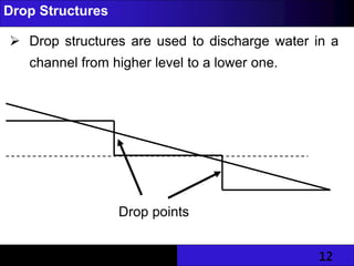
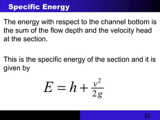
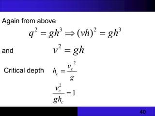
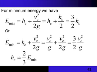
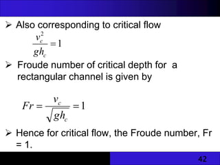
1
Unlined and Lined Channels
 Unlined earth channels are often found in irrigation
projects as conveyance systems on the farms.
 Advantages of earth unlined channels include the
facts that:
• They are understood and accepted by farmers
• They can be built and maintained by unskilled
labour
• They do not require special equipment or materials
• Construction materials are locally available
2
Construction of Earth Channels – Some facts
 They should be built with stable side slopes and with
banks strong enough to carry the required flow safely.
 They should have ample capacity to carry the design flow
at non-erosive velocities.
 Side slopes should be flat enough so that the banks will
neither cave in nor slide when they are saturated with
water.
 For stiff clay, steep slopes up to ½ to 1 are possible.
 Loose sand should have flat slopes of about 2 to 1.
 Channels constructed higher than the surrounding field
level should have banks large enough to withstand
damage by seepage.
3
 Earth channels are lined with impervious
materials to prevent excessive seepage and
growth of weeds.
Water losses in unlined channels may occur by:
 Seepage
 Breaches along the channel through rat holes
 Ponding of water in depressions and
irregularities in the channel section
 Evaporation
 The length of the channel affects the quantity of
water lost by seepage and evaporation
4
 One of the main problems in the use of unlined
channels is the control of weeds.
 Weeds in a channel obstruct the flow of water.
 Unlined channels require continuous
maintenance to:
 Control weed growth
 Repair damage by livestock, rodents
 Control erosion
Problems Associated with Unlined Channels
5
Typical Values of Manning’s n
MATERIALS MANNING’S N
EARTH CHANNELS 0.023~ 0.04
LINED CHANNELS
CONCRETE 0.015
MASONRY 0.017~ 0.03
METAL, SMOOTH 0.011~ 0.015
WOODEN 0.011 ~ 0.014
VEGETATED WATERWAY 0.02 ~ 0.04
PIPES
CAST IRON 0.012 ~ 0.013
CLAY OR CONCRETE DRAIN TILE 0.011
STEEL 0.015 ~ 0.017
VITRIFIED SEWER PIPE 0.013 ~ 0.015
6
Importance of Lining of Earth Channels
 Avoid excessive loss of water by seepage
 Avoid piping through or under banks
 Provide needed stability
 Avoid erosion
 Avoid water logging of adjacent lands
 Promote the continued movements of sediments
 Facilitate cleaning
 Promote economy by a reduction in excavation
 Reduce flow resistance
 Aid in the control of weeds and aquatic growths
7
Some materials for lining:
 Concrete
 Brick or stone masonry
 Asphalt lining
 Compacted earth lining
 Pre-cast concrete
8
Permissible Slope of Earth Channels
 Natural slope of the land is usually the deciding
factor in determining the channel bed slope.
 The steeper the channel, the more will be the
velocity and the more the discharge for the same
cross-section.
 High slopes will result in high velocities which
cause erosion.
 Earth channel should have a gradient of about 0.1
%.
 Silting may occur if the channel has a slope less
than 0.05%.
9
 When bed slopes of channels is to be
determined, the velocity should be checked so
that it does not exceed a certain maximum – thus
avoiding erosion.
 Where earth channels are to be used on steep
slopes, it is necessary to control the gradients
and hence the velocity by constructing drop
structures or lining the channel bed.
Permissible Slope of Earth Channels
10
Permissible Velocities for Various Soil Textures
SOIL TYPE
MAXIMUM
PERMISSIBLE
VELOCITY (m/s)
BARE CHANNELS
SAND AND SILT 0.45
LOAM, SANDY LOAM, SILT LOAM 0.6
CLAY LOAM 0.65
VEGETATED CHANNELS
POOR VEGETATION 0.9
FAIR VEGETATION 1.2
GOOD VEGETATION 1.5
11
Structures for Controlling Erosion in Channels
(Irrigation)
 it is sometimes necessary to build channels on
land slopes so steep that the water will attain
erosive velocities.
 Severe erosion will occur in earth channels if
structures to control the slope are not provided.
 Drop structures and chute drops are used to
prevent erosion in channels.
12
Drop Structures
 Drop structures are used to discharge water in a
channel from higher level to a lower one.
Drop points
13
Drop Structures
 They may be open type drops or pipe drops.
 Open drop structures can be made of
 Timber,
 Concrete,
 Brick
 Stone masonry.
 Timber is usually not preferred due to its short life.
14
15
Chute Spillways
 Chute spillways carry flow down steep slopes
through a lined channel rather than by dropping
the water in free overfall.
 A chute spillway consists of an inlet, channel
section and an outlet.
 The structure may be made of concrete, or
stone, or bricks laid in cement mortar.
16
Chute spillway of Livn
Brianne dam in Wales
17
Check gate
10~20 cm
shaft
1~2 m
18
Water Control and Diversion Structures
 Water control and diversion structures are
necessary to give easy and effective control of
irrigation water on the farm.
 Good control will reduce the labour required to
irrigate and check erosion and water loss.
 The structures include check gates, portable
check dams, diversion boxes, turnout boxes,
siphons and pipe turnouts.
19
Nomographic Design of Open Channels
 The nomograph allows fast determination of the
mean velocity of flow when the values of R, S, and
n are given.
 It can also be used to determine the value of
anyone of the factors R, S, n and v when any
three of the factors are known.
20
Nomographic Design of Open Channels
 To use the nomograph, a line is drawn to join S and
n values on the respective scales, and passing
through the pivot line.
 The point of the intersection of this line with the
pivot line is the pivot point.
 A line originating from the known value on the R
scale and passing through the pivot point when
extended to meet the velocity scale provides the
required value of the velocity.
21
22
Factor Determining the Choice of Channel Geometry
Main purpose: To transport water between
two points in a safe, cost-effective
manner.
Hydraulic Effectiveness: Hydraulically the
most effective section is one which has the
minimum perimeter for a particular cross-
sectional area. The circular section is
thus the most efficient. Excavation and
lining cost decrease as the channel
approaches the hydraulically most efficient
shape.
Stability of side slopes: this is generally
determined by the material through which
the channel runs.
23
Factor Determining the Choice of Channel Geometry
Contours of the Land: Possible gradients
between terminal points are determined by
landmark and economy. The gradient
determines the velocity( Manning and Chezy).
Sediments: If its not possible to prevent
suspended sediment from entering the
channel, it is necessary to make sure that
the velocity is sufficient to carry it away
otherwise it will settle and impair the
efficiency of the channel.
Permeability Problems: The channel material
maybe porous enough to allow seepage of
flowing water. If loss of water is
undesirable, lining may be required.
24
Factor Determining the Choice of Channel Geometry
Uncontrollable natural factors: Water
plants, burrowing animals and human beings.
Accessibility for maintenance
25
NON-UNIFORM FLOW
 In considering uniform flow, the assumption is that
successive cross-sections and corresponding mean
velocities were the same everywhere.
 The loss of head in friction was equal to the fall of
the channel bed.
 Means the following characteristics are all parallel.
 Channel bed,
 Water surface
 Energy gradient.
26
 For non-uniform flow, conditions for uniform
flow does not apply.
 Depth of flow vary from section to section.
 The following characteristics will no longer be
parallel.
 Energy gradient,
 Water surface
 Channel bed.
 Non-uniform flows are produced by changes in the
channel geometry, while changing from one
uniform flow to another
27
There are two types of non-uniform flows
 Rapidly varied flow, in which the change in depth
takes place over a short distance, hence friction,
can be neglected.
 Gradually varied flow, in which the change in
depth extends over a long distance.
28
Datum
Water surface (slope=Sw)
Channel bottom (slope=So)
Energy gradeline (slope=Sf)
Z1
h1
Z2
h2
v2
1/ 2g
v2
2/ 2g
1
2
Energy Principle
29
The total energy possessed by a body (volume)
of water flowing in an open channel is given by
Dividing through by mg, (per unit weight) yields
2
2
mv
mgH
ETotal 

g
v
H
ETotal
2
2

 m
30
Volume of water V (m3) positioned at elevation Z
(m) with flow depth h (m), possesses the
following amount of potential energy:
Total energy in the open channel flowing with
water at depth h is given by:
H
Z
Epotential 

g
v
total h
Z
E 2
2



31
 Writing the energy equation between two sections
(sections 1 and 2) in the channel gives
Where Z=elevation of the channel bottom above an
arbitrary datum;
h = the depth of flow; v=average velocity;
HL= head loss between sections 1 and 2.
But because rapidly varied flow occurs within a short
distance, HL = 0
L
H
g
v
h
Z
g
v
h
Z 





2
2
2
2
2
2
1
1
2
1
32
The energy with respect to the channel bottom is
the sum of the flow depth and the velocity head
at the section.
This is the specific energy of the section and it is
given by
g
v
h
E 2
2


Specific Energy
33
Consider a steady non-uniform flow.
Let: Width of the channel be b,
Steady rate of flow be Q.
Then the discharge per unit width will be
therefore
b
Q
q  = constant (Since Q = const, and b = const)
v - velocity at the section given by
A
Q
bh
Q
v 

2
2
2gA
Q
h
E 

34
 At various sections of the channel the depth of flow
will change with corresponding change in velocity
so that the product “vh” is constant at all sections.
 At any section,
  2
2
2
2
1
2
2
2
2
h
h
h
h
E g
q
gh
q
g
v






35
Where
– static (potential) energy head
– kinetic energy head
h
E 
1
2
2
2
1
2 h
g
q
E 






 For a given value of q, the specific energy head
is a function of the depth of flow
2
1 E
E
E 

36
 When depth of flow is plotted against the specific
energy for a given channel section and discharge,
a specific energy curve is obtained.
 Specific Energy Curve BCD, shows that
 The Specific Energy Head (CD), first
decreases with increase in depth and reaches
a minimum value of C. (Supercritical flow
zone)
 Further increase in depth causes a
corresponding increase in the Specific Energy
(CB). (Sub-critical flow zone)
37
Specific Energy Curve
Depth of flow, h
E2 Curve
E = y B
E = E1 + E2 Curve
Sub-critical Zone
Super critical zone
Specific Energy, E
I
C
H
G
Emin
E
D
h1
hc
h2
45o
O
38
 Consider the line GHI.
 The specific energy for this condition is EI = OG, but
the flow depth may be either GH or GI.
 The depth GH = h1 is less than the critical depth hc,
while the depth GI = h2 is greater than the critical
depth.
 The flow is supercritical when h1 < hc, and it is
subcritical when h2 > hc.
 When the depth of flow is hc, the flow is called
critical flow, and the velocity, vc, is called critical
velocity.
 The depths h1 and h2 are known as alternate
depths.
39
Critical Flow
Rectangular Sections
Given the specific energy head
For minimum E,
2
2
2
2
2 gh
q
g
v
h
h
E 



0

dh
dE
3
2
1 gh
q
dh
dE


3
2
g
q
hc  = critical depth
40
Again from above
and
Critical depth
3
2
3
2
)
( gh
vh
gh
q 


gh
v 
2
g
v
h c
c
2

1
2

c
c
gh
v
41
For minimum energy we have
c
c
c
c
c h
h
h
g
v
h
E
2
3
2
2
2
min 




Or
g
v
g
v
g
v
g
v
h
E c
c
c
c
c
2
2
2
2
min
2
3
2
2





min
3
2
E
hc 
42
 Also corresponding to critical flow
 Froude number of critical depth for a
rectangular channel is given by
 Hence for critical flow, the Froude number, Fr
= 1.
1
2

c
c
gh
v
1


c
c
gh
v
Fr

Hydraulics Notes 3_ One Slide on a page.pdf

  • 1.
    1 Unlined and LinedChannels  Unlined earth channels are often found in irrigation projects as conveyance systems on the farms.  Advantages of earth unlined channels include the facts that: • They are understood and accepted by farmers • They can be built and maintained by unskilled labour • They do not require special equipment or materials • Construction materials are locally available
  • 2.
    2 Construction of EarthChannels – Some facts  They should be built with stable side slopes and with banks strong enough to carry the required flow safely.  They should have ample capacity to carry the design flow at non-erosive velocities.  Side slopes should be flat enough so that the banks will neither cave in nor slide when they are saturated with water.  For stiff clay, steep slopes up to ½ to 1 are possible.  Loose sand should have flat slopes of about 2 to 1.  Channels constructed higher than the surrounding field level should have banks large enough to withstand damage by seepage.
  • 3.
    3  Earth channelsare lined with impervious materials to prevent excessive seepage and growth of weeds. Water losses in unlined channels may occur by:  Seepage  Breaches along the channel through rat holes  Ponding of water in depressions and irregularities in the channel section  Evaporation  The length of the channel affects the quantity of water lost by seepage and evaporation
  • 4.
    4  One ofthe main problems in the use of unlined channels is the control of weeds.  Weeds in a channel obstruct the flow of water.  Unlined channels require continuous maintenance to:  Control weed growth  Repair damage by livestock, rodents  Control erosion Problems Associated with Unlined Channels
  • 5.
    5 Typical Values ofManning’s n MATERIALS MANNING’S N EARTH CHANNELS 0.023~ 0.04 LINED CHANNELS CONCRETE 0.015 MASONRY 0.017~ 0.03 METAL, SMOOTH 0.011~ 0.015 WOODEN 0.011 ~ 0.014 VEGETATED WATERWAY 0.02 ~ 0.04 PIPES CAST IRON 0.012 ~ 0.013 CLAY OR CONCRETE DRAIN TILE 0.011 STEEL 0.015 ~ 0.017 VITRIFIED SEWER PIPE 0.013 ~ 0.015
  • 6.
    6 Importance of Liningof Earth Channels  Avoid excessive loss of water by seepage  Avoid piping through or under banks  Provide needed stability  Avoid erosion  Avoid water logging of adjacent lands  Promote the continued movements of sediments  Facilitate cleaning  Promote economy by a reduction in excavation  Reduce flow resistance  Aid in the control of weeds and aquatic growths
  • 7.
    7 Some materials forlining:  Concrete  Brick or stone masonry  Asphalt lining  Compacted earth lining  Pre-cast concrete
  • 8.
    8 Permissible Slope ofEarth Channels  Natural slope of the land is usually the deciding factor in determining the channel bed slope.  The steeper the channel, the more will be the velocity and the more the discharge for the same cross-section.  High slopes will result in high velocities which cause erosion.  Earth channel should have a gradient of about 0.1 %.  Silting may occur if the channel has a slope less than 0.05%.
  • 9.
    9  When bedslopes of channels is to be determined, the velocity should be checked so that it does not exceed a certain maximum – thus avoiding erosion.  Where earth channels are to be used on steep slopes, it is necessary to control the gradients and hence the velocity by constructing drop structures or lining the channel bed. Permissible Slope of Earth Channels
  • 10.
    10 Permissible Velocities forVarious Soil Textures SOIL TYPE MAXIMUM PERMISSIBLE VELOCITY (m/s) BARE CHANNELS SAND AND SILT 0.45 LOAM, SANDY LOAM, SILT LOAM 0.6 CLAY LOAM 0.65 VEGETATED CHANNELS POOR VEGETATION 0.9 FAIR VEGETATION 1.2 GOOD VEGETATION 1.5
  • 11.
    11 Structures for ControllingErosion in Channels (Irrigation)  it is sometimes necessary to build channels on land slopes so steep that the water will attain erosive velocities.  Severe erosion will occur in earth channels if structures to control the slope are not provided.  Drop structures and chute drops are used to prevent erosion in channels.
  • 12.
    12 Drop Structures  Dropstructures are used to discharge water in a channel from higher level to a lower one. Drop points
  • 13.
    13 Drop Structures  Theymay be open type drops or pipe drops.  Open drop structures can be made of  Timber,  Concrete,  Brick  Stone masonry.  Timber is usually not preferred due to its short life.
  • 14.
  • 15.
    15 Chute Spillways  Chutespillways carry flow down steep slopes through a lined channel rather than by dropping the water in free overfall.  A chute spillway consists of an inlet, channel section and an outlet.  The structure may be made of concrete, or stone, or bricks laid in cement mortar.
  • 16.
    16 Chute spillway ofLivn Brianne dam in Wales
  • 17.
  • 18.
    18 Water Control andDiversion Structures  Water control and diversion structures are necessary to give easy and effective control of irrigation water on the farm.  Good control will reduce the labour required to irrigate and check erosion and water loss.  The structures include check gates, portable check dams, diversion boxes, turnout boxes, siphons and pipe turnouts.
  • 19.
    19 Nomographic Design ofOpen Channels  The nomograph allows fast determination of the mean velocity of flow when the values of R, S, and n are given.  It can also be used to determine the value of anyone of the factors R, S, n and v when any three of the factors are known.
  • 20.
    20 Nomographic Design ofOpen Channels  To use the nomograph, a line is drawn to join S and n values on the respective scales, and passing through the pivot line.  The point of the intersection of this line with the pivot line is the pivot point.  A line originating from the known value on the R scale and passing through the pivot point when extended to meet the velocity scale provides the required value of the velocity.
  • 21.
  • 22.
    22 Factor Determining theChoice of Channel Geometry Main purpose: To transport water between two points in a safe, cost-effective manner. Hydraulic Effectiveness: Hydraulically the most effective section is one which has the minimum perimeter for a particular cross- sectional area. The circular section is thus the most efficient. Excavation and lining cost decrease as the channel approaches the hydraulically most efficient shape. Stability of side slopes: this is generally determined by the material through which the channel runs.
  • 23.
    23 Factor Determining theChoice of Channel Geometry Contours of the Land: Possible gradients between terminal points are determined by landmark and economy. The gradient determines the velocity( Manning and Chezy). Sediments: If its not possible to prevent suspended sediment from entering the channel, it is necessary to make sure that the velocity is sufficient to carry it away otherwise it will settle and impair the efficiency of the channel. Permeability Problems: The channel material maybe porous enough to allow seepage of flowing water. If loss of water is undesirable, lining may be required.
  • 24.
    24 Factor Determining theChoice of Channel Geometry Uncontrollable natural factors: Water plants, burrowing animals and human beings. Accessibility for maintenance
  • 25.
    25 NON-UNIFORM FLOW  Inconsidering uniform flow, the assumption is that successive cross-sections and corresponding mean velocities were the same everywhere.  The loss of head in friction was equal to the fall of the channel bed.  Means the following characteristics are all parallel.  Channel bed,  Water surface  Energy gradient.
  • 26.
    26  For non-uniformflow, conditions for uniform flow does not apply.  Depth of flow vary from section to section.  The following characteristics will no longer be parallel.  Energy gradient,  Water surface  Channel bed.  Non-uniform flows are produced by changes in the channel geometry, while changing from one uniform flow to another
  • 27.
    27 There are twotypes of non-uniform flows  Rapidly varied flow, in which the change in depth takes place over a short distance, hence friction, can be neglected.  Gradually varied flow, in which the change in depth extends over a long distance.
  • 28.
    28 Datum Water surface (slope=Sw) Channelbottom (slope=So) Energy gradeline (slope=Sf) Z1 h1 Z2 h2 v2 1/ 2g v2 2/ 2g 1 2 Energy Principle
  • 29.
    29 The total energypossessed by a body (volume) of water flowing in an open channel is given by Dividing through by mg, (per unit weight) yields 2 2 mv mgH ETotal   g v H ETotal 2 2   m
  • 30.
    30 Volume of waterV (m3) positioned at elevation Z (m) with flow depth h (m), possesses the following amount of potential energy: Total energy in the open channel flowing with water at depth h is given by: H Z Epotential   g v total h Z E 2 2   
  • 31.
    31  Writing theenergy equation between two sections (sections 1 and 2) in the channel gives Where Z=elevation of the channel bottom above an arbitrary datum; h = the depth of flow; v=average velocity; HL= head loss between sections 1 and 2. But because rapidly varied flow occurs within a short distance, HL = 0 L H g v h Z g v h Z       2 2 2 2 2 2 1 1 2 1
  • 32.
    32 The energy withrespect to the channel bottom is the sum of the flow depth and the velocity head at the section. This is the specific energy of the section and it is given by g v h E 2 2   Specific Energy
  • 33.
    33 Consider a steadynon-uniform flow. Let: Width of the channel be b, Steady rate of flow be Q. Then the discharge per unit width will be therefore b Q q  = constant (Since Q = const, and b = const) v - velocity at the section given by A Q bh Q v   2 2 2gA Q h E  
  • 34.
    34  At varioussections of the channel the depth of flow will change with corresponding change in velocity so that the product “vh” is constant at all sections.  At any section,   2 2 2 2 1 2 2 2 2 h h h h E g q gh q g v      
  • 35.
    35 Where – static (potential)energy head – kinetic energy head h E  1 2 2 2 1 2 h g q E         For a given value of q, the specific energy head is a function of the depth of flow 2 1 E E E  
  • 36.
    36  When depthof flow is plotted against the specific energy for a given channel section and discharge, a specific energy curve is obtained.  Specific Energy Curve BCD, shows that  The Specific Energy Head (CD), first decreases with increase in depth and reaches a minimum value of C. (Supercritical flow zone)  Further increase in depth causes a corresponding increase in the Specific Energy (CB). (Sub-critical flow zone)
  • 37.
    37 Specific Energy Curve Depthof flow, h E2 Curve E = y B E = E1 + E2 Curve Sub-critical Zone Super critical zone Specific Energy, E I C H G Emin E D h1 hc h2 45o O
  • 38.
    38  Consider theline GHI.  The specific energy for this condition is EI = OG, but the flow depth may be either GH or GI.  The depth GH = h1 is less than the critical depth hc, while the depth GI = h2 is greater than the critical depth.  The flow is supercritical when h1 < hc, and it is subcritical when h2 > hc.  When the depth of flow is hc, the flow is called critical flow, and the velocity, vc, is called critical velocity.  The depths h1 and h2 are known as alternate depths.
  • 39.
    39 Critical Flow Rectangular Sections Giventhe specific energy head For minimum E, 2 2 2 2 2 gh q g v h h E     0  dh dE 3 2 1 gh q dh dE   3 2 g q hc  = critical depth
  • 40.
    40 Again from above and Criticaldepth 3 2 3 2 ) ( gh vh gh q    gh v  2 g v h c c 2  1 2  c c gh v
  • 41.
    41 For minimum energywe have c c c c c h h h g v h E 2 3 2 2 2 min      Or g v g v g v g v h E c c c c c 2 2 2 2 min 2 3 2 2      min 3 2 E hc 
  • 42.
    42  Also correspondingto critical flow  Froude number of critical depth for a rectangular channel is given by  Hence for critical flow, the Froude number, Fr = 1. 1 2  c c gh v 1   c c gh v Fr