Downloaded 161 times
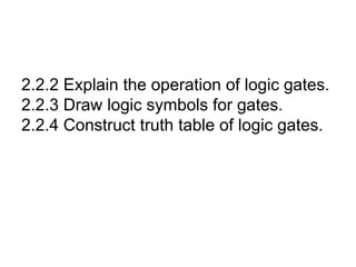
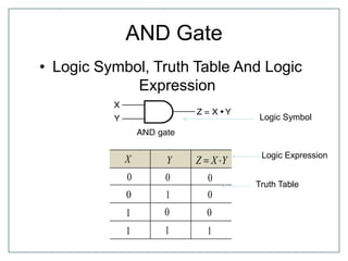
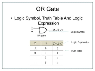
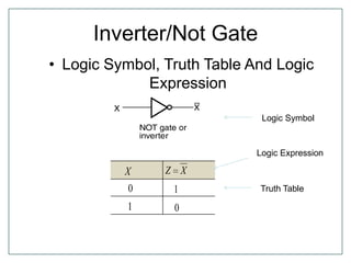
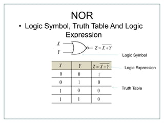
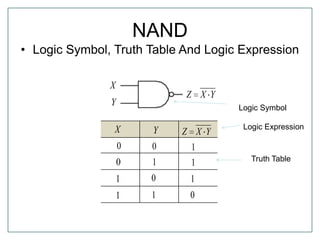
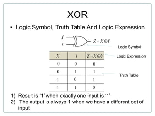
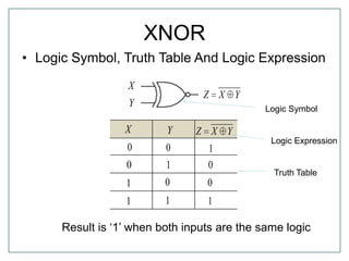
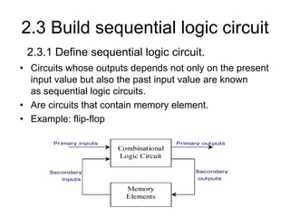
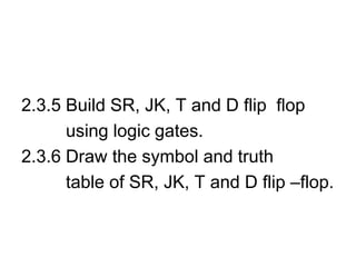
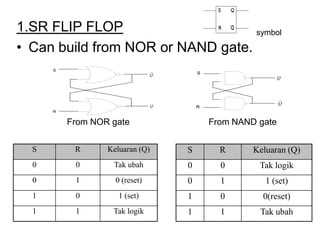
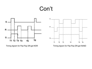
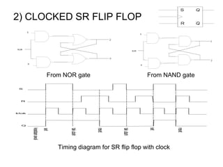
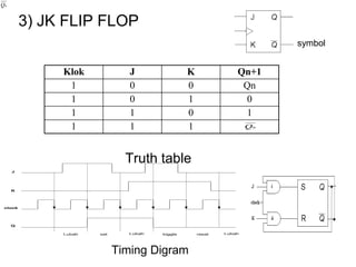
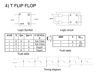
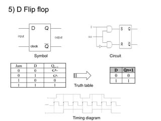
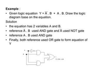
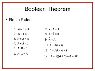
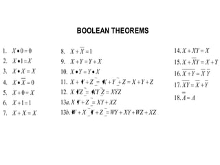
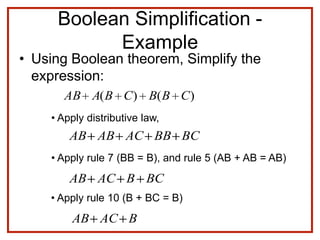
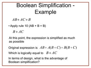
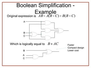
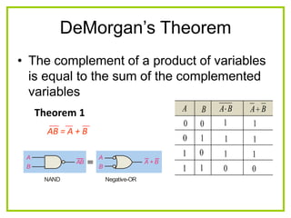
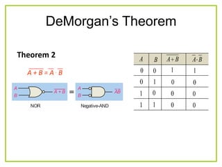
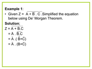
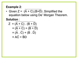
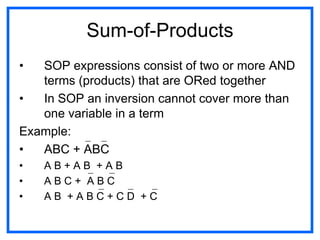
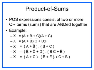
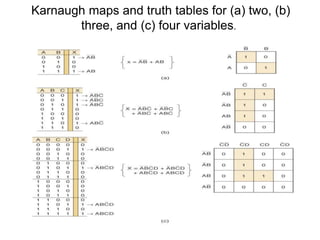
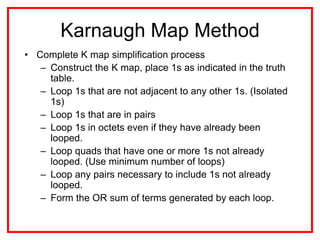

The document discusses Boolean algebra and logic gates. It defines logic gates, explains their operations, and provides their logic symbols and truth tables. The types of logic gates covered are AND, OR, NOT, NOR, NAND, XOR, and XNOR. It also discusses sequential logic circuits like flip-flops, providing details on SR, JK, T, and D flip-flops including how to build them using logic gates. Additional topics covered include the difference between combinational and sequential logic circuits, Boolean theorems, sum-of-products and product-of-sums expressions, and the Karnaugh map method for simplifying logic expressions.