https://www.udemy.com/vlsi-academy
http://vlsisystemdesign.com/need_for_decap.php
A decoupling capacitor is a capacitor, which is used decouple the critical cells from main power supply, in order to protect the cells from the disturbance occuring in the power distribution lines and source. The purpose of using decoupling capacitors is to deliver current to the gates during switching. Herein, we would peep inside the reasons for the distrubance occuring in the power distribution lines.
Low Power VLSI design architecture for EDA (Electronic Design Automation) and Modern Power Estimation, Reduction and Fixing technologies including clock gating and power gating
The document discusses various layout optimizations that can be made to standard cells to reduce both internal power and area. These include removing "hammer head" structures to decrease transistor length, moving gate contacts over active areas to reduce transistor height, and reducing source/drain capacitances to decrease dynamic current without impacting speed. Post-layout simulations showed a new D flip-flop design with these optimizations reduced internal power by 20% while maintaining clock-to-Q delay, and improved saturation current by 15-50% while reducing area by 20%.
https://www.udemy.com/vlsi-academy
Usually, while drawing any circuit on paper, we have only one 'vdd' at the top and one 'vss' at the bottom. But on a chip, it becomes necessary to have a grid structure of power, with more than one 'vdd' and 'vss'. The concept of power grid structure would be uploaded soon. It is actually the scaling trend that drives chip designers for power grid structure.
The document discusses minimizing crosstalk in VLSI routing. It begins with an overview of routing and discusses global routing versus detailed routing. It then covers crosstalk effects, including inductive and capacitive coupling between wires. Approaches to avoid crosstalk include segregating wires, increasing spacing, assigning wires to different layers, and estimating and minimizing crosstalk during routing. Techniques for detailed routing include net ordering, layer assignment, and rip-up and reroute to meet crosstalk constraints.
Routing in Integrated circuits is an important task which requires extreme care while placing the modules and circuits and connecting them with each other.
Signal Integrity - A Crash Course [R Lott]Ryan Lott
This document provides an introduction to signal integrity for interconnects. It discusses typical interconnects like PCB traces, cables, and connectors and the signal integrity problems they can cause, such as loss, reflections, crosstalk, and ringing. It also introduces concepts like characteristic impedance, frequency-dependent loss, and how signals propagate as electromagnetic waves. Measurement techniques like S-parameters and using a vector network analyzer are discussed as ways to characterize devices in the frequency domain.
This document summarizes techniques for minimizing crosstalk in VLSI designs. It discusses the VLSI design cycle and physical design cycle. Routing is a key stage that involves global and detailed routing. Crosstalk occurs due to mutual inductance and capacitance between wires and can affect signal integrity, delay, and timing. Basic approaches to reduce crosstalk include segregating wires, increasing spacing between wires, using ground shields, optimizing the net ordering and layer assignments. Specific techniques mentioned are widening spacing, minimizing wire heights and lengths of parallel runs, using differential routing, and routing orthogonal layers.
1. The document discusses the key steps in physical design flow, including import design, floorplanning, placement and routing.
2. Floorplanning is described as a critical step, where the quality of the floorplan can significantly impact timing closure and design implementation. Good techniques for floorplanning include understanding the design requirements and data flow.
3. The document outlines the major steps in floorplanning such as sizing and shaping blocks, voltage area creation, pin placement, row creation, macro placement, adding blockages and special cells. Qualifying the floorplan involves checks on pin grids, design rules, power connections and more.
Visit https://www.vlsiuniverse.com/
https://www.vlsiuniverse.com/2020/05/complete-asic-design-flow.html
This is the standard VLSI design flow that every semiconductor company follows. The complete ASIC design flow is explained by considering each and every stage.
This document discusses low-noise amplifier (LNA) design. It begins by describing the basic function and placement of an LNA in an RF receiver front end. Key considerations for LNA design include noise performance, power transfer, impedance matching, power consumption, bandwidth, stability, and linearity. Various techniques for impedance matching an LNA are then discussed, including resistive termination, series-shunt feedback, and common-gate configuration. The common-gate structure provides input matching without additional passive components.
This document discusses physical design verification checks that are performed on an integrated circuit layout. It describes design rule checking (DRC) which checks that a layout adheres to foundry design rules for manufacturability. Layout versus schematic (LVS) checks that the layout connectivity matches the schematic netlist. Electrical rule checking (ERC) identifies electrical issues like floating devices or short circuits. The document provides examples of DRC, LVS, and ERC checks and typical issues found during these verification steps.
This document discusses important considerations for analog integrated circuit layout and the CMOS fabrication process. It covers topics like MOS transistor operation, analog signal characteristics, CMOS fabrication steps, layout techniques for minimizing noise and mismatches, and avoiding latch-up issues. The key goals of analog layout include matching devices, minimizing parasitic capacitance and resistance, isolating analog and digital sections, and using guard rings and decoupling capacitors.
As we push through lower technology nodes in the IC and chip design, the wire width goes thinner along with transistor size. This makes the wire resistance more dominant on 16nm and below technology nodes. This increasing resistance and the decreasing width of metal wires introduce many Electromigration and IR drop issues. These two issues play major roles in reducing the lifespan of an electronic device and are the causes of functionality failure in any electronic devices with lower technology nodes.
In this article, we will discuss the problems of electromigration and IR drop, and techniques to prevent the occurrence of these issues in electronic devices.
Electromigration is the gradual displacement of metal atoms in a semiconductor. It occurs when the current density is high enough to cause the drift of metal ions in the direction of the electron flow, and is characterized by the ion flux density. This density depends on the magnitude of forces that tend to hold the ions in place, i.e., the nature of the conductor, crystal size, interface and grain-boundary chemistry, and the magnitude of forces that tend to dislodge them, including the current density, temperature and mechanical stresses.
The Power supply in the chip is distributed uniformly through metal layers (Vdd & Vss) across the design. These metal layers have finite amount of resistance. When voltage is applied to this metal wires current starts flowing through the metal layers and some voltage is dropped due to that resistance of metal wires and current. this drop is called as IR drop.
The document provides an overview of the ASIC back-end design flow, including physical design steps like floorplanning, timing driven placement, clock tree synthesis, and routing. It explains key concepts in physical design like standard cell libraries, placement, routing grids and tracks, and timing driven optimization. The document also discusses verification steps after physical design like formal verification to check logic equivalence and timing analysis using RC extraction and static timing analysis to check design constraints.
The document discusses complex programmable logic devices (CPLDs) and field programmable gate arrays (FPGAs). CPLDs contain multiple programmable logic blocks called PAL-like blocks that can be interconnected, while FPGAs contain logic blocks in the form of lookup tables that can implement any function. Both CPLDs and FPGAs allow users to program logic functions and connections between blocks. However, FPGAs can implement larger designs using more logic blocks and gates than CPLDs. The document also covers the architecture, programming, and applications of CPLDs and FPGAs.
The document provides an overview of analog layout design. It discusses that analog circuits require careful attention to geometry during layout due to process variations. The analog design flow includes electrical design, physical design involving layout, and fabrication/testing. Key considerations for analog layout include minimizing parasitic resistances and capacitances, reducing noise, and ensuring matching between identical components using techniques like common-centroid layout. Resistors and capacitors must be carefully laid out to minimize non-ideal effects and provide accurate values.
Define Width and Height of Core and Die (http://www.vlsisystemdesign.com/PD-F...VLSI SYSTEM Design
https://www.udemy.com/vlsi-academy
The very first step in chip design is floorplanning, in which the width and height of the chip, basically the area of the chip, is defined. A chip consists of two parts, 'core' and 'die'.
The physical design flow begins with placement which involves assigning exact locations to modules like gates and standard cells to minimize area and interconnect cost while meeting timing constraints, with the goal of enabling easier routing; placement tools take as input the netlist, floorplan, libraries, and constraints to perform global and detailed placement as well as optimization. The quality of placement significantly impacts the ability to route the design successfully.
This document discusses the key inputs required for the physical design phase of a VLSI chip, using Synopsys tools as an example. The main inputs are: (1) a gate-level netlist describing the logical connections, (2) libraries providing timing, power and physical information for standard cells and macros, (3) a technology file describing manufacturing details, (4) parasitic extraction files (TLU+) for timing analysis, and (5) constraints describing design objectives. Additional inputs include floorplanning guidelines, scenarios for optimization, and reference design methodologies. The goal of physical design is to implement the logic from the netlist while meeting area, timing and power targets.
The document summarizes the physical design flow for integrated circuits and routing algorithms. It discusses the objectives of routing to minimize wire length for general purpose chips and meet timing budgets for high performance chips. Global routing algorithms like maze routing and Lee algorithm are described. Maze routing works by propagating a wavefront from source to target and backtracking the shortest path. The Lee algorithm finds the shortest two-terminal connection on a grid using this approach.
Power gating is the main power reduction techniques for the static power. As long as technology scaling is taking place, static power becomes paramount important factor to the VLSI designs.Therefore Power gating is the recent power reduction technique that is actively in research areas.
Nanometer layout handbook at high speed designMinho Park
I made this contents for whom is about to layout own's IC design. I think it would be helpful to consider layouts about high speed Rx / Tx.
Specially it was aimed giga hertz bandwidth I/O with its ESD protection (I am still working on that items to rearrange with my knowledge to my experiences)
I showed up all references and all images (except originals) are belong to own's copy rights.
The document discusses floor planning, which is the first step in physical design. It involves defining the size of the chip, pre-placing hard macros, I/O pads, and defining the power grid. A good floorplan partitions the design into functional blocks, arranges the blocks on the chip, places macros and I/O pads, and decides on the power distribution. Key inputs to floorplanning include the netlist, physical and timing libraries, timing constraints, and power requirements. The document then discusses various aspects of floorplanning such as die size calculations, macro placement guidelines, and different types of physical cells.
This document discusses the layout of analog CMOS integrated circuits. It focuses on the layout of transistors and basic cells. Key topics covered include:
- Layout of a single transistor, use of multiple fingers, and interdigitated transistors for matching.
- Common centroid layouts and dummy devices to reduce mismatch.
- Ensuring matched interconnect resistance, capacitance, and parasitics.
- Stacked layout of analog cells with stick diagrams to represent multiple transistors.
- Two examples of laying out basic cells - a two-stage op-amp and folded cascode. Design considerations like transistor sizing and grouping are discussed.
Timing and Design Closure in Physical Design Flows Olivier Coudert
A physical design flow consists of producing a production-worthy layout from a gate-level netlist subject to a set of constraints. We focus on the problems imposed by shrinking process technologies. It exposes the problems of timing closure, signal integrity, design variable dependencies, clock and power/ground routing, and design signoff. It also surveys some physical design flows, and outlines a refinement-based flow.
Clippers and clampers are diode-based circuits used to modify signal waveforms. Clippers eliminate portions of an input signal to "clip" the waveform, and are used to remove noise or create new waveforms. They come in series and parallel types. Series clippers place the diode in series with the load, and clip voltages that don't forward bias the diode. Parallel clippers take the output across the diode, producing the voltage when it is not conducting. Clampers "clamp" a signal to a different DC level using a capacitor, diode, and resistor. The capacitor stores a reference voltage to set the output level when the diode is non-conducting.
This document discusses the basics of bipolar junction transistors (BJTs). It begins by explaining that BJTs and field effect transistors are the two main categories of transistors. It then discusses the first transistor developed by Bardeen and Brattain in 1947. The document explains the symbol for an NPN or PNP BJT and describes the collector, base, and emitter layers. It provides details on the fabrication process and structure of discrete and planar BJTs. Oxide and trench isolation techniques are also summarized, along with the use of double polysilicon layers to reduce transistor size.
https://www.udemy.com/vlsi-academy
http://vlsisystemdesign.com/noise_margin.php
Noise margin is the amount of noise that a CMOS circuit could withstand without compromising the operation of circuit. Noise margin does makes sure that any signal which is logic '1' with finite noise added to it, is still recognised as logic '1' and not logic '0'. It is basically the difference between signal value and the nosie value.
https://www.udemy.com/vlsi-academy
http://vlsisystemdesign.com/place_decap.php
Once the critical cells are placed on the chip, it becomes necessary to surround the critical cells by decoupling capacitors. The placement of de-coupling capacitors surrounding the pre-placed cells improves the reliability and efficiency of the chip.
The document discusses Boolean algebra and logic gates. It defines logic gates, explains their operations, and provides their logic symbols and truth tables. The types of logic gates covered are AND, OR, NOT, NOR, NAND, XOR, and XNOR. It also discusses sequential logic circuits like flip-flops, providing details on SR, JK, T, and D flip-flops including how to build them using logic gates. Additional topics covered include the difference between combinational and sequential logic circuits, Boolean theorems, sum-of-products and product-of-sums expressions, and the Karnaugh map method for simplifying logic expressions.
This document provides an overview of VLSI system design and microelectronics history. It discusses the increasing complexity of microelectronics over time. It also outlines the key steps in the VLSI design process, from high-level architecture design to logic design, layout, and verification.
This document discusses the CMOS inverter. It explains the switch models of the CMOS inverter and how the input signals determine whether the NMOS or PMOS transistor is on. It also discusses the properties of static CMOS inverters, including their voltage transfer characteristic curve and noise margins. The document describes how process variations and supply voltage scaling can impact the inverter's performance. Finally, it examines the dynamic behavior of the CMOS inverter and the parasitic capacitances that affect its switching speeds.
The document discusses placement in physical design. It describes placement as assigning positions to predesigned cells on a chip without overlapping to optimize objectives like minimizing area and interconnects. It discusses different placement types, formulates the placement problem, and describes algorithms like partitioning-based placement, simulated annealing placement, and iterative placement methods.
A capacitor is a device that stores electrons and is made up of two conductors separated by an insulator. Capacitors come in different sizes, shapes, and models and can store varying amounts of charge depending on their design. There are several types of capacitors including non-polarized capacitors that can be connected either way in a circuit, polarized capacitors that must be connected correctly, variable capacitors whose capacitance can be adjusted, and trimmer capacitors designed to be set during circuit assembly.
The document discusses how switching activity in a device can affect the voltage levels of input/output signals. It explains that for a signal to be considered logic '1' or '0', its voltage should fall within the normal markup level (NMH) or normal markup low (NML) ranges, respectively. The summary discusses how a capacitor needs a peak current to charge up to the supply voltage level for the output of an inverter to be recognized as logic '1'.
le roludes the tiofuture research directionsARNABPAL81
ully distributed formation-containment control protocol for networked MASs with timevarying formation reference. Two detailed case studies are considered in Section 4.4 to
show the effectiveness of the proposed methodology. One of them deals with the formationcontainment of a team of networked satellites, and the other one shows experimental validation using nonholonomic mobile robots. Section 4.5 concludes the chapter mentioning the
future research directions
This document describes the operation of a DC-DC buck converter, which efficiently reduces DC voltage. It consists of an inductor, capacitor, switch, and diode. When the switch is closed, the inductor stores energy from the input voltage. When open, the diode allows the inductor to discharge its current to the output through the capacitor and load. By rapidly switching at a duty cycle D, the average output voltage is Vin * D. The document analyzes current and voltage waveforms, deriving key equations for output voltage, component ratings, and output ripple voltage. Raising switching frequency or inductance reduces ripple.
This document describes operational amplifiers and their use in various circuit configurations. It defines the key properties of an ideal operational amplifier as having infinite gain, infinite input impedance, and zero output impedance. Circuits diagrams are provided for inverting and non-inverting amplifiers. Expressions are derived for the gain of inverting and non-inverting amplifiers. Additional sections describe using an op-amp as a comparator, Schmitt trigger, and solving problems involving various op-amp circuits.
The document describes the operation and design considerations of a buck/boost DC-DC converter circuit. It provides equations to calculate component ratings for the input inductor, output capacitor, MOSFET, diode, and other parts. Design examples are given to illustrate how to select appropriate component values and ratings to ensure continuous inductor currents and minimize output voltage ripple.
The document discusses the design and operation of a buck-boost DC-DC converter circuit. It provides details on component sizing, current and voltage ratings, and worst-case analyses. Key aspects covered include inductor and capacitor sizing to limit ripple current and voltage, MOSFET and diode voltage and current ratings, and concluding that 50kHz may be too low a switching frequency for this buck-boost converter design.
This document discusses DC-DC buck converters. It begins by introducing different types of DC-DC converters and their applications. It then explains the objective of a buck converter is to efficiently reduce DC voltage. It discusses how a simple inefficient converter can achieve only 33% efficiency. Through the addition of an inductor and diode, lossless conversion becomes possible. The document explains the operating principles of the buck converter through examination of the inductor voltage and capacitor current in steady state. It derives the input-output voltage relationship and discusses how varying different circuit parameters affects the inductor current waveform. Finally, it covers RMS calculations for common periodic waveforms seen in converter circuits.
This document discusses dependent sources and operational amplifiers. It defines dependent sources as voltage or current sources whose value is controlled by another voltage or current in the circuit. Their value is the product of a constant gain and the controlling voltage or current. The document then discusses various op-amp configurations like inverting amplifiers, non-inverting amplifiers, summing amplifiers, and integrators. It explains how feedback is used to stabilize the op-amp and achieve a desired gain. The document also provides an overview of digital to analog converters and how they reconstruct analog waveforms from digital samples.
The document describes an algorithm for synthesizing a system-level bus from a set of communication channels. The algorithm determines the optimal bus width to balance performance and interconnect cost. It computes the bus rate based on width and delay, and channel rates based on data access patterns and transfer sizes. The bus rate must be greater than or equal to the peak rates of the channels to avoid bottlenecks. The algorithm relates the bus and channel rates to efficiently implement the channels with a single bus.
1. The document discusses DC-DC buck converters and their operation. A buck converter efficiently steps down DC voltage through lossless conversion using a switch, inductor, diode, and capacitor.
2. When the switch is closed, the inductor current rises and energy is stored in the inductor's magnetic field. When the switch opens, the inductor current flows through the diode to the load. By rapidly switching on and off, the output voltage is the average of the input voltage over many switching cycles.
3. Key aspects covered include inductor and capacitor behavior, the input/output voltage relationship, effects of varying duty cycle and switching frequency, and RMS current calculations. Proper component selection is important for continuous
This document provides an introduction and overview of chopper circuits, which are power electronics devices that can convert a fixed DC voltage into a variable DC voltage.
It defines a chopper as a high-speed switch that connects and disconnects a load from a power source rapidly to produce a variable output voltage. Choppers can either step up or step down the output voltage relative to the input.
Different types of choppers are described including step-down, step-up, buck-boost, and various configurations classified by their operating quadrants on a voltage-current plane (types A, B, and C). Key components like switches, diodes, and inductors are also outlined.
The SEPIC converter is a type of DC-DC converter that allows the output voltage to be greater than, less than, or equal to the input voltage. It uses two inductors and two capacitors in a unique configuration to achieve this. While more complex than a basic boost or buck converter, the SEPIC converter has advantages like having no average current pass through one of the capacitors and allowing impedance matching across the full operating range of a solar panel. Key components are rated for higher voltages and currents than a basic buck-boost converter.
This document summarizes a lecture on the MOS switch and MOS diode. It discusses the MOSFET as an ideal and non-ideal switch, including the influence of on resistance, off resistance, and parasitic capacitances. It describes channel charge injection that occurs when the switch turns off and clock feedthrough from the gate capacitance. Models are presented to analyze the varying on resistance during switching and the effects of charge injection and clock feedthrough. Methods for reducing these non-ideal effects are also discussed, such as minimizing parasitic capacitances and transition times.
This document discusses inverters and logic gates in VLSI design. It begins with an outline of topics covered, including nMOS and CMOS inverters, inverter characteristics, switching times, and CMOS logic structures. Diagrams and equations are provided to illustrate the DC and transient characteristics of inverters, including transfer characteristics, regions of operation, and rise/fall times. Design considerations for cascading inverters and driving large loads are also addressed. Transmission gates and static/dynamic CMOS design are briefly introduced.
The following presentation is a part of the level 5 module -- Electronic Engineering. This resources is a part of the 2009/2010 Engineering (foundation degree, BEng and HN) courses from University of Wales Newport (course codes H101, H691, H620, HH37 and 001H). This resource is a part of the core modules for the full time 1st year undergraduate programme.
The BEng & Foundation Degrees and HNC/D in Engineering are designed to meet the needs of employers by placing the emphasis on the theoretical, practical and vocational aspects of engineering within the workplace and beyond. Engineering is becoming more high profile, and therefore more in demand as a skill set, in today’s high-tech world. This course has been designed to provide you with knowledge, skills and practical experience encountered in everyday engineering environments.
This document provides an overview of choppers, which are DC-DC converters that create adjustable DC voltage from a fixed DC source. There are two main types: AC link choppers, which convert DC to AC and back, and DC choppers, which directly convert DC voltage. DC choppers can be step-up or step-down depending on the circuit configuration. Chopper circuits are further classified by their operating quadrant as types A through E. Type A operates only in the first quadrant to step down voltage, while type B can step up voltage and operates in the second quadrant to provide regenerative braking.
1) The document discusses a DC-DC buck converter that efficiently reduces a DC voltage. It examines the operation of buck converters including the input/output voltage relationship and how varying different circuit parameters affects the inductor current waveform.
2) Key circuit elements like the inductor and capacitor are analyzed in the time domain to understand their average voltages and currents. RMS current calculations are also provided for determining proper component ratings.
3) Different operating modes like continuous and discontinuous conduction are covered, and the voltages different components need to withstand are identified to select appropriate voltage ratings.
This document discusses operational amplifiers (op-amps) and their applications in linear circuits. It begins by introducing op-amps, their ideal characteristics including very high gain and zero input current. It then explains how op-amps can be used to construct inverting amplifiers, non-inverting amplifiers, followers, and circuits for analog addition and subtraction through negative or positive feedback. Circuits are analyzed using the ideal op-amp model of infinite gain and input impedance. Simulation results are also presented verifying the circuit analysis.
This document discusses the design and operation of a boost converter circuit. It notes that boost converters are more unforgiving than buck converters if components fail or the load is disconnected. The document derives the input-output voltage relationship for boost converters and calculates important design parameters like inductor and capacitor current ratings, voltage ratings for components, and impedance matching considerations. It provides an example of using a boost converter to extract maximum power from a solar panel by modifying the effective load resistance seen by the panel. Tables compare worst-case component ratings and output capacitor ripple voltages for boost converters.
This presentation was provided by Rebecca Benner, Ph.D., of the American Society of Anesthesiologists, for the second session of NISO's 2024 Training Series "DEIA in the Scholarly Landscape." Session Two: 'Expanding Pathways to Publishing Careers,' was held June 13, 2024.
Chapter wise All Notes of First year Basic Civil Engineering.pptxDenish Jangid
Chapter wise All Notes of First year Basic Civil Engineering
Syllabus
Chapter-1
Introduction to objective, scope and outcome the subject
Chapter 2
Introduction: Scope and Specialization of Civil Engineering, Role of civil Engineer in Society, Impact of infrastructural development on economy of country.
Chapter 3
Surveying: Object Principles & Types of Surveying; Site Plans, Plans & Maps; Scales & Unit of different Measurements.
Linear Measurements: Instruments used. Linear Measurement by Tape, Ranging out Survey Lines and overcoming Obstructions; Measurements on sloping ground; Tape corrections, conventional symbols. Angular Measurements: Instruments used; Introduction to Compass Surveying, Bearings and Longitude & Latitude of a Line, Introduction to total station.
Levelling: Instrument used Object of levelling, Methods of levelling in brief, and Contour maps.
Chapter 4
Buildings: Selection of site for Buildings, Layout of Building Plan, Types of buildings, Plinth area, carpet area, floor space index, Introduction to building byelaws, concept of sun light & ventilation. Components of Buildings & their functions, Basic concept of R.C.C., Introduction to types of foundation
Chapter 5
Transportation: Introduction to Transportation Engineering; Traffic and Road Safety: Types and Characteristics of Various Modes of Transportation; Various Road Traffic Signs, Causes of Accidents and Road Safety Measures.
Chapter 6
Environmental Engineering: Environmental Pollution, Environmental Acts and Regulations, Functional Concepts of Ecology, Basics of Species, Biodiversity, Ecosystem, Hydrological Cycle; Chemical Cycles: Carbon, Nitrogen & Phosphorus; Energy Flow in Ecosystems.
Water Pollution: Water Quality standards, Introduction to Treatment & Disposal of Waste Water. Reuse and Saving of Water, Rain Water Harvesting. Solid Waste Management: Classification of Solid Waste, Collection, Transportation and Disposal of Solid. Recycling of Solid Waste: Energy Recovery, Sanitary Landfill, On-Site Sanitation. Air & Noise Pollution: Primary and Secondary air pollutants, Harmful effects of Air Pollution, Control of Air Pollution. . Noise Pollution Harmful Effects of noise pollution, control of noise pollution, Global warming & Climate Change, Ozone depletion, Greenhouse effect
Text Books:
1. Palancharmy, Basic Civil Engineering, McGraw Hill publishers.
2. Satheesh Gopi, Basic Civil Engineering, Pearson Publishers.
3. Ketki Rangwala Dalal, Essentials of Civil Engineering, Charotar Publishing House.
4. BCP, Surveying volume 1
Beyond Degrees - Empowering the Workforce in the Context of Skills-First.pptxEduSkills OECD
Iván Bornacelly, Policy Analyst at the OECD Centre for Skills, OECD, presents at the webinar 'Tackling job market gaps with a skills-first approach' on 12 June 2024
How Barcodes Can Be Leveraged Within Odoo 17Celine George
In this presentation, we will explore how barcodes can be leveraged within Odoo 17 to streamline our manufacturing processes. We will cover the configuration steps, how to utilize barcodes in different manufacturing scenarios, and the overall benefits of implementing this technology.
ISO/IEC 27001, ISO/IEC 42001, and GDPR: Best Practices for Implementation and...PECB
Denis is a dynamic and results-driven Chief Information Officer (CIO) with a distinguished career spanning information systems analysis and technical project management. With a proven track record of spearheading the design and delivery of cutting-edge Information Management solutions, he has consistently elevated business operations, streamlined reporting functions, and maximized process efficiency.
Certified as an ISO/IEC 27001: Information Security Management Systems (ISMS) Lead Implementer, Data Protection Officer, and Cyber Risks Analyst, Denis brings a heightened focus on data security, privacy, and cyber resilience to every endeavor.
His expertise extends across a diverse spectrum of reporting, database, and web development applications, underpinned by an exceptional grasp of data storage and virtualization technologies. His proficiency in application testing, database administration, and data cleansing ensures seamless execution of complex projects.
What sets Denis apart is his comprehensive understanding of Business and Systems Analysis technologies, honed through involvement in all phases of the Software Development Lifecycle (SDLC). From meticulous requirements gathering to precise analysis, innovative design, rigorous development, thorough testing, and successful implementation, he has consistently delivered exceptional results.
Throughout his career, he has taken on multifaceted roles, from leading technical project management teams to owning solutions that drive operational excellence. His conscientious and proactive approach is unwavering, whether he is working independently or collaboratively within a team. His ability to connect with colleagues on a personal level underscores his commitment to fostering a harmonious and productive workplace environment.
Date: May 29, 2024
Tags: Information Security, ISO/IEC 27001, ISO/IEC 42001, Artificial Intelligence, GDPR
-------------------------------------------------------------------------------
Find out more about ISO training and certification services
Training: ISO/IEC 27001 Information Security Management System - EN | PECB
ISO/IEC 42001 Artificial Intelligence Management System - EN | PECB
General Data Protection Regulation (GDPR) - Training Courses - EN | PECB
Webinars: https://pecb.com/webinars
Article: https://pecb.com/article
-------------------------------------------------------------------------------
For more information about PECB:
Website: https://pecb.com/
LinkedIn: https://www.linkedin.com/company/pecb/
Facebook: https://www.facebook.com/PECBInternational/
Slideshare: http://www.slideshare.net/PECBCERTIFICATION
🔥🔥🔥🔥🔥🔥🔥🔥🔥
إضغ بين إيديكم من أقوى الملازم التي صممتها
ملزمة تشريح الجهاز الهيكلي (نظري 3)
💀💀💀💀💀💀💀💀💀💀
تتميز هذهِ الملزمة بعِدة مُميزات :
1- مُترجمة ترجمة تُناسب جميع المستويات
2- تحتوي على 78 رسم توضيحي لكل كلمة موجودة بالملزمة (لكل كلمة !!!!)
#فهم_ماكو_درخ
3- دقة الكتابة والصور عالية جداً جداً جداً
4- هُنالك بعض المعلومات تم توضيحها بشكل تفصيلي جداً (تُعتبر لدى الطالب أو الطالبة بإنها معلومات مُبهمة ومع ذلك تم توضيح هذهِ المعلومات المُبهمة بشكل تفصيلي جداً
5- الملزمة تشرح نفسها ب نفسها بس تكلك تعال اقراني
6- تحتوي الملزمة في اول سلايد على خارطة تتضمن جميع تفرُعات معلومات الجهاز الهيكلي المذكورة في هذهِ الملزمة
واخيراً هذهِ الملزمة حلالٌ عليكم وإتمنى منكم إن تدعولي بالخير والصحة والعافية فقط
كل التوفيق زملائي وزميلاتي ، زميلكم محمد الذهبي 💊💊
🔥🔥🔥🔥🔥🔥🔥🔥🔥
Gender and Mental Health - Counselling and Family Therapy Applications and In...PsychoTech Services
A proprietary approach developed by bringing together the best of learning theories from Psychology, design principles from the world of visualization, and pedagogical methods from over a decade of training experience, that enables you to: Learn better, faster!
Philippine Edukasyong Pantahanan at Pangkabuhayan (EPP) CurriculumMJDuyan
(𝐓𝐋𝐄 𝟏𝟎𝟎) (𝐋𝐞𝐬𝐬𝐨𝐧 𝟏)-𝐏𝐫𝐞𝐥𝐢𝐦𝐬
𝐃𝐢𝐬𝐜𝐮𝐬𝐬 𝐭𝐡𝐞 𝐄𝐏𝐏 𝐂𝐮𝐫𝐫𝐢𝐜𝐮𝐥𝐮𝐦 𝐢𝐧 𝐭𝐡𝐞 𝐏𝐡𝐢𝐥𝐢𝐩𝐩𝐢𝐧𝐞𝐬:
- Understand the goals and objectives of the Edukasyong Pantahanan at Pangkabuhayan (EPP) curriculum, recognizing its importance in fostering practical life skills and values among students. Students will also be able to identify the key components and subjects covered, such as agriculture, home economics, industrial arts, and information and communication technology.
𝐄𝐱𝐩𝐥𝐚𝐢𝐧 𝐭𝐡𝐞 𝐍𝐚𝐭𝐮𝐫𝐞 𝐚𝐧𝐝 𝐒𝐜𝐨𝐩𝐞 𝐨𝐟 𝐚𝐧 𝐄𝐧𝐭𝐫𝐞𝐩𝐫𝐞𝐧𝐞𝐮𝐫:
-Define entrepreneurship, distinguishing it from general business activities by emphasizing its focus on innovation, risk-taking, and value creation. Students will describe the characteristics and traits of successful entrepreneurs, including their roles and responsibilities, and discuss the broader economic and social impacts of entrepreneurial activities on both local and global scales.
BÀI TẬP BỔ TRỢ TIẾNG ANH LỚP 9 CẢ NĂM - GLOBAL SUCCESS - NĂM HỌC 2024-2025 - ...
Need of Decoupling Capacitor
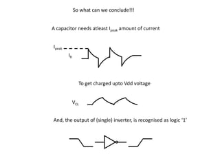
1. So what can we conclude!!!
A capacitor needs atleast Ipeak amount of current
Ipeak
IR
To get charged upto Vdd voltage
VCL
And, the output of (single) inverter, is recognised as logic ‘1’
2. Consider the amount of the switching current required
For a complex block something like below
3. Consider the amount of the switching current required
For a complex block something like below
4. Why to do?
1. If the wires were ideal,
i.e. 'zero' resistance, 'zero'
inductance and infinitely
short, thus no issue of
power distribution
3/2/2013 4
5. Why to do?
1. Consider capacitance to be zero
for the discussion. Rdd, Rss, Ldd
and Lss are well defined values.
2. During switching operation, the
circuit demands switching
current i.e. peak current (Ipeak).
3. Now, due to the presence of Rdd
and Ldd, there will be a voltage
drop across them and the
voltage at Node 'A' would be
Vdd' instead of Vdd.
3/2/2013 5
6. Why to do?
1. When input of the inverter
switches from logic '1' to logic
'0', output of inverter should
switch from logic '0' to logic '1'.
2. This essentially means that the
output capacitance of inverter
should charge till the supply
voltage Vdd'.
3. But if Vdd' goes below the
noise margin, due to Rdd and
Ldd, the logic '1' at the output
of inverter wont be detected
as logic '1' at the input of the Vdd - Vdd' = Ipeak*Rdd + Ldd * (dI/dt)
circuit following the inverter.
3/2/2013 6
7. Why to do?
Solution
1. Keep Rdd and Rss minimum by
increasing width of wire.
2. Keep peak current Ipeak and
change in current dI/dt as
small as possible.
Ipeak = CL * Vdd / tr
dI/dt = CL * Vdd / tr2
3. Limit the rise time (tr). If a
circuit could run at 500 ps, its
unnecessary to run the circuit
at 300 ps. The largest possible
value of tr should be selected. Vdd - Vdd' = Ipeak*Rdd + Ldd * (dI/dt)
3/2/2013 7
8. Why to do?
1. Addition of Decoupling
Capacitor in parallel with the
circuit
2. Everytime the critical cell (in
above daigram,an inverter)
switches, it draws current from
Cd , whereas, the RL network is
used to replenish the charge
into Cd
3/2/2013 8
41. V V V 0 0 V 0 V V V 0 0 0 V V 0
Now, Lets the output of 16 – bit bus, is connected to an inverter
42. V V V 0 0 V 0 V V V 0 0 0 V V 0
Now, Lets the output of 16 – bit bus, is connected to an inverter
1110010111000110
16-bit bus
16-bit bus
43. V V V 0 0 V 0 V V V 0 0 0 V V 0
Now, Lets the output of 16 – bit bus, is connected to an inverter
1110010111000110
16-bit bus
16-bit bus
0001101000111001
44. V V V 0 0 V 0 V V V 0 0 0 V V 0
0001101000111001
45. V V V 0 0 V 0 V V V 0 0 0 V V 0
0001101000111001
What does this mean?
46. V V V 0 0 V 0 V V V 0 0 0 V V 0
0001101000111001
What does this mean?
This means, all capacitors which were charged to ‘V’ volts will have to discharge to ‘0’ volts
through single ‘Ground’ tap point. This will cause a bump in ‘Ground’ tap point.
47. V V V 0 0 V 0 V V V 0 0 0 V V 0
0001101000111001
What does this mean?
This means, all capacitors which were charged to ‘V’ volts will have to discharge to ‘0’ volts
through single ‘Ground’ tap point. This will cause a bump in ‘Ground’ tap point.
V V V 0 0 V 0 V V V 0 0 0 V V 0
48. V V V 0 0 V 0 V V V 0 0 0 V V 0
0001101000111001
What does this mean?
This means, all capacitors which were charged to ‘V’ volts will have to discharge to ‘0’ volts
through single ‘Ground’ tap point. This will cause a bump in ‘Ground’ tap point.
V V V 0 0 V 0 V V V 0 0 0 V V 0
49. V V V 0 0 V 0 V V V 0 0 0 V V 0
0001101000111001
What does this mean?
This means, all capacitors which were charged to ‘V’ volts will have to discharge to ‘0’ volts
through single ‘Ground’ tap point. This will cause a bump in ‘Ground’ tap point.
V V V 0 0 V 0 V V V 0 0 0 V V 0
Ground Bounce
50. V V V 0 0 V 0 V V V 0 0 0 V V 0
0001101000111001
What does this mean?
51. V V V 0 0 V 0 V V V 0 0 0 V V 0
0001101000111001
What does this mean?
Also, all capacitors which were ‘0’ volts will have to charge to ‘V’ volts
through single ‘Vdd’ tap point. This will cause lowering of voltage at ‘Vdd’ tap point.
52. V V V 0 0 V 0 V V V 0 0 0 V V 0
0001101000111001
What does this mean?
Also, all capacitors which were ‘0’ volts will have to charge to ‘V’ volts
through single ‘Vdd’ tap point. This will cause lowering of voltage at ‘Vdd’ tap point.
V V V 0 0 V 0 V V V 0 0 0 V V 0
53. V V V 0 0 V 0 V V V 0 0 0 V V 0
0001101000111001
What does this mean?
Also, all capacitors which were ‘0’ volts will have to charge to ‘V’ volts
through single ‘Vdd’ tap point. This will cause lowering of voltage at ‘Vdd’ tap point.
V V V 0 0 V 0 V V V 0 0 0 V V 0
54. V V V 0 0 V 0 V V V 0 0 0 V V 0
0001101000111001
What does this mean?
Also, all capacitors which were ‘0’ volts will have to charge to ‘V’ volts
through single ‘Vdd’ tap point. This will cause lowering of voltage at ‘Vdd’ tap point.
Voltage Droop
V V V 0 0 V 0 V V V 0 0 0 V V 0
57. So what could be the solution ?
Driver
Load
How can ‘Driver’ and ‘Load’ can be brought close to each other in ‘L’ sense ?
58. If ‘Driver’ and ‘Load’ have a lot of communication between them, then
the power supply network must be designed in such a way, that they are
Inductively close to each other
59. If ‘Driver’ and ‘Load’ have a lot of communication between them, then
the power supply network must be designed in such a way, that they are
Inductively close to each other
So, how do we design power supply distribution network?
60. If ‘Driver’ and ‘Load’ have a lot of communication between them, then
the power supply network must be designed in such a way, that they are
Inductively close to each other
So, how do we design power supply distribution network?
MESH!!!!
66. Power should not be coming only from one place
But from many places
67. Power should not be coming only from one place
But from many places
Assume that, the boundary power is available, now we have to get it inside the chip
68. Power should not be coming only from one place
But from many places
Assume that, the boundary power is available, now we have to get it inside the chip
Thus, local communication is taken care by de-coupling capacitors
69. Power should not be coming only from one place
But from many places
Assume that, the boundary power is available, now we have to get it inside the chip
Thus, local communication is taken care by de-coupling capacitors
And, common rail inductance coupling issue is taken care by power mesh
70. DECAP1
D
Block a Block b
4
DECAP2
Block c
DECAP3
Die
Vss Core
Vdd