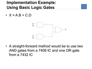
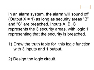
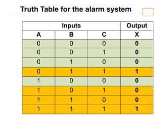
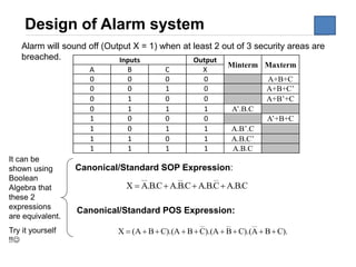
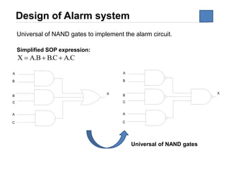
The document discusses logic circuit optimization techniques including Boolean algebra, De Morgan's theorems, and Karnaugh maps. It provides examples of simplifying logic expressions using Boolean algebra rules and theorems. Specifically, it shows how to implement the logic function for an alarm system that activates when two of three security areas are breached, using sum of products and NAND gate implementations.

![8
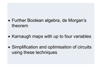
Rules of Boolean Algebra
Rule Prove ( For your information only)
The double complement of a variable is always equal to
the variable.
A + AB = A
A + AB = A (1 + B) [ Distributive Law ]
= A.1 [ Rule 2: (1 + B) = 1 ]
= A [ Rule 4: A.1 = A ]
(A + B)(A + C) = A + BC
(A + B)(A + C) = AA + AC + AB + BC [Distributive Law]
= A + AC + AB + BC [Rule 7: AA = A]
= A (1 + C) + AB + BC [Rule 2: 1 + C = 1]
= A.1 + AB + BC Factoring
= A (1 + B) + BC [Rule 2: 1 + B = 1]
= A.1 + BC [Rule 4: A.1 = A]
= A + BC](https://image.slidesharecdn.com/4logiccircuitoptimisation-190620040524/85/4-logic-circuit-optimisation-5-320.jpg)

![11
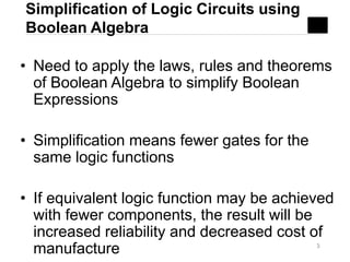
Example [1] – De Morgan’s
BA+
).( ZYX +
= (A’ + B’)’
= [(A’)’.(B’)’]
= A.B
= (X.Y’ + Z)’
= (X.Y’)’.Z’
= (X’+Y).Z’
= X’.Z’ + Y.Z’](https://image.slidesharecdn.com/4logiccircuitoptimisation-190620040524/85/4-logic-circuit-optimisation-8-320.jpg)
![12
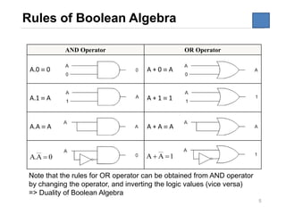
Example [2] –De Morgan’s
ZYX ++
).).(.( CBACBA ++
= (X’+Y’)’. (Z’)’
= [(X’)’,(Y’)’]. (Z)
= [X.Y]. Z
= X.Y.Z
= (A.B’+C)’ + (A+BC)’
= (AB’)’C’ + A’(BC)’
= (A’+B)C’ + A’(B’+C’)
= A’C’ + BC’ + A’B’ + A’C’
= A’C’ + BC’ + A’B’](https://image.slidesharecdn.com/4logiccircuitoptimisation-190620040524/85/4-logic-circuit-optimisation-9-320.jpg)