Downloaded 722 times
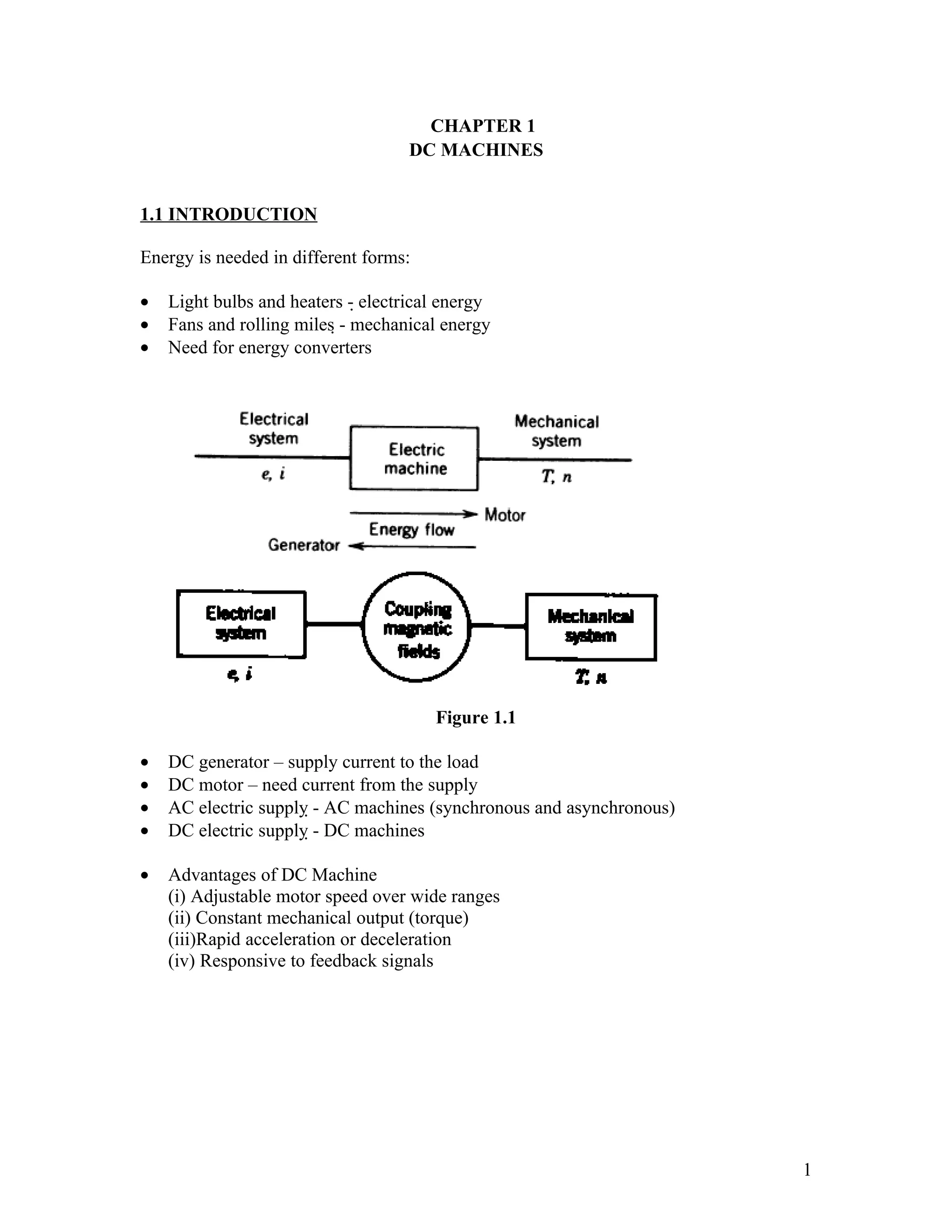
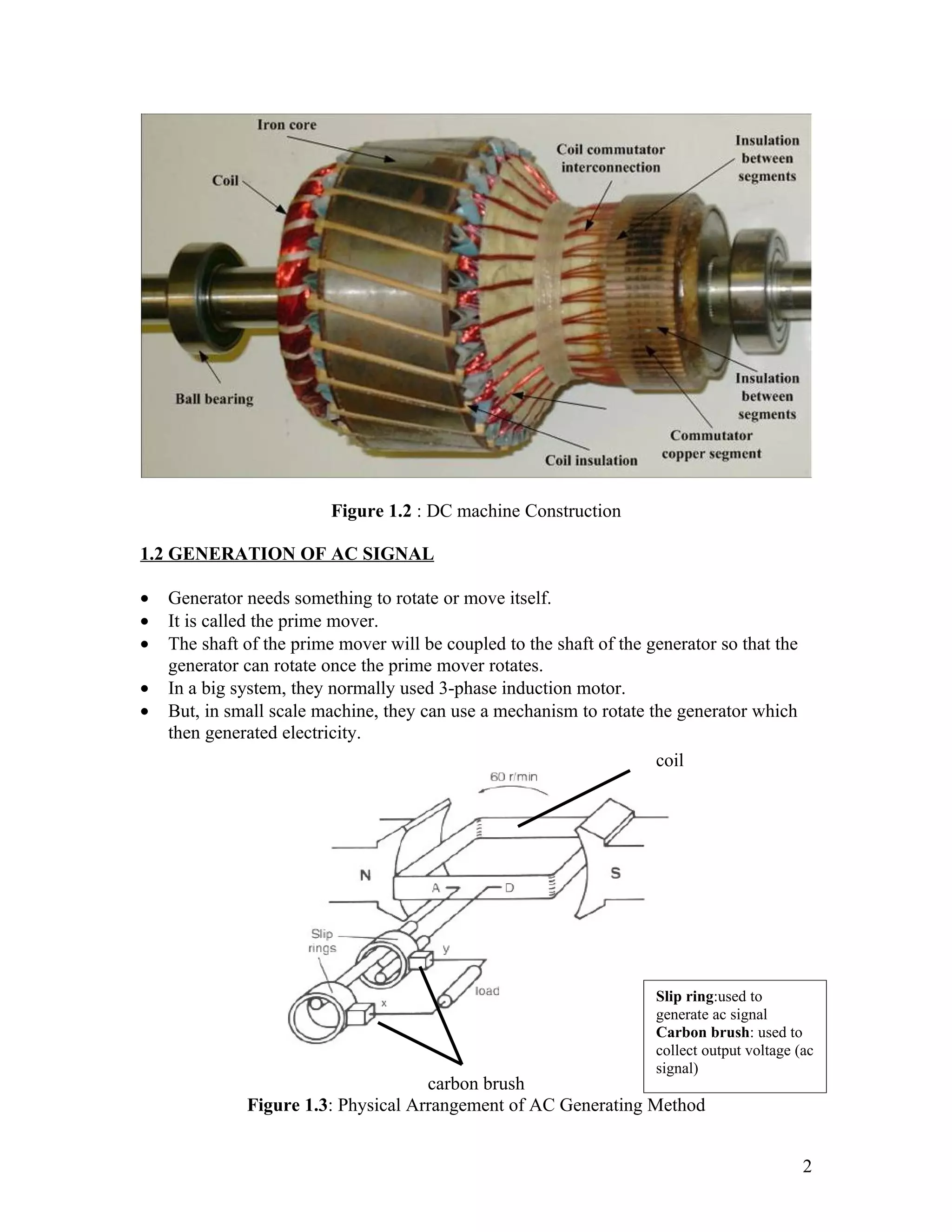
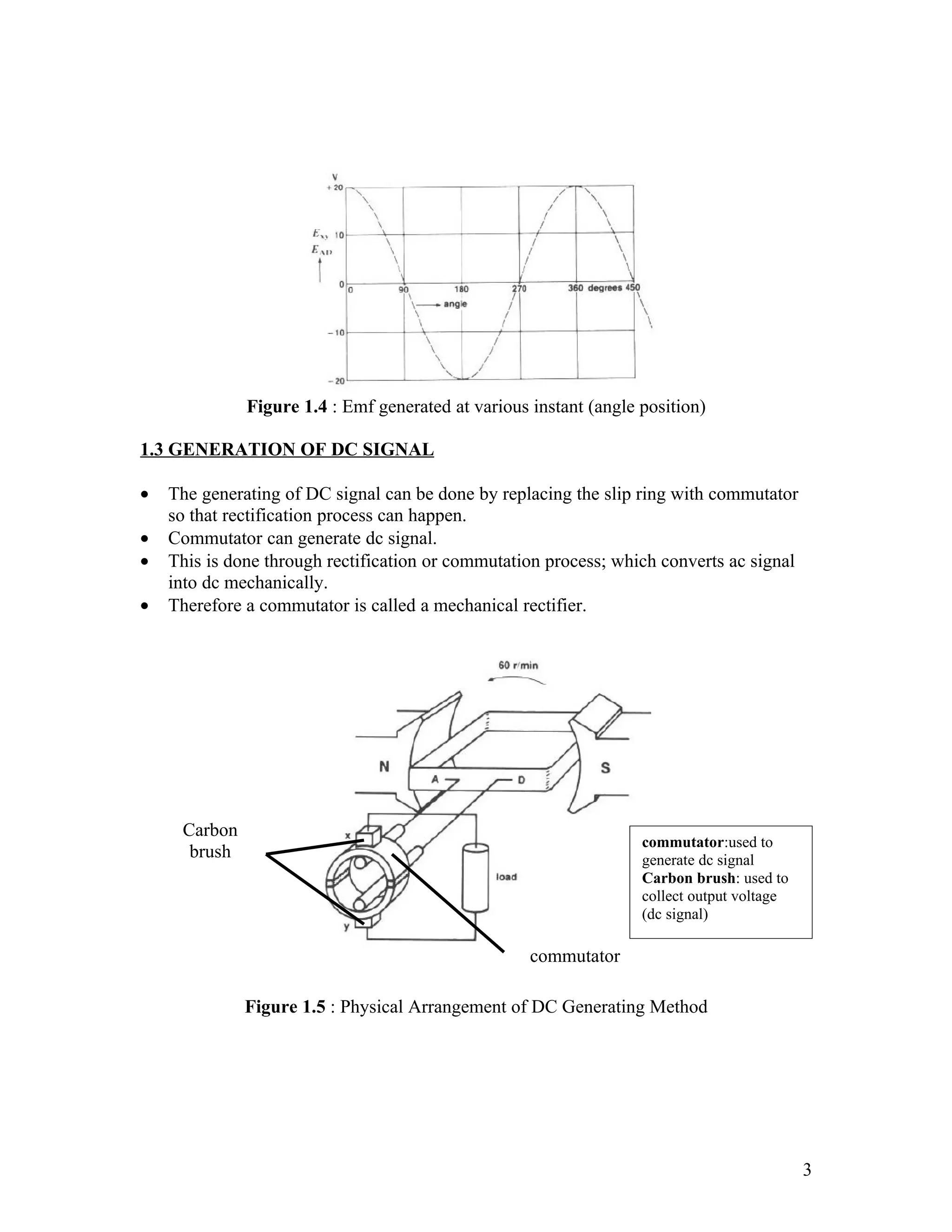
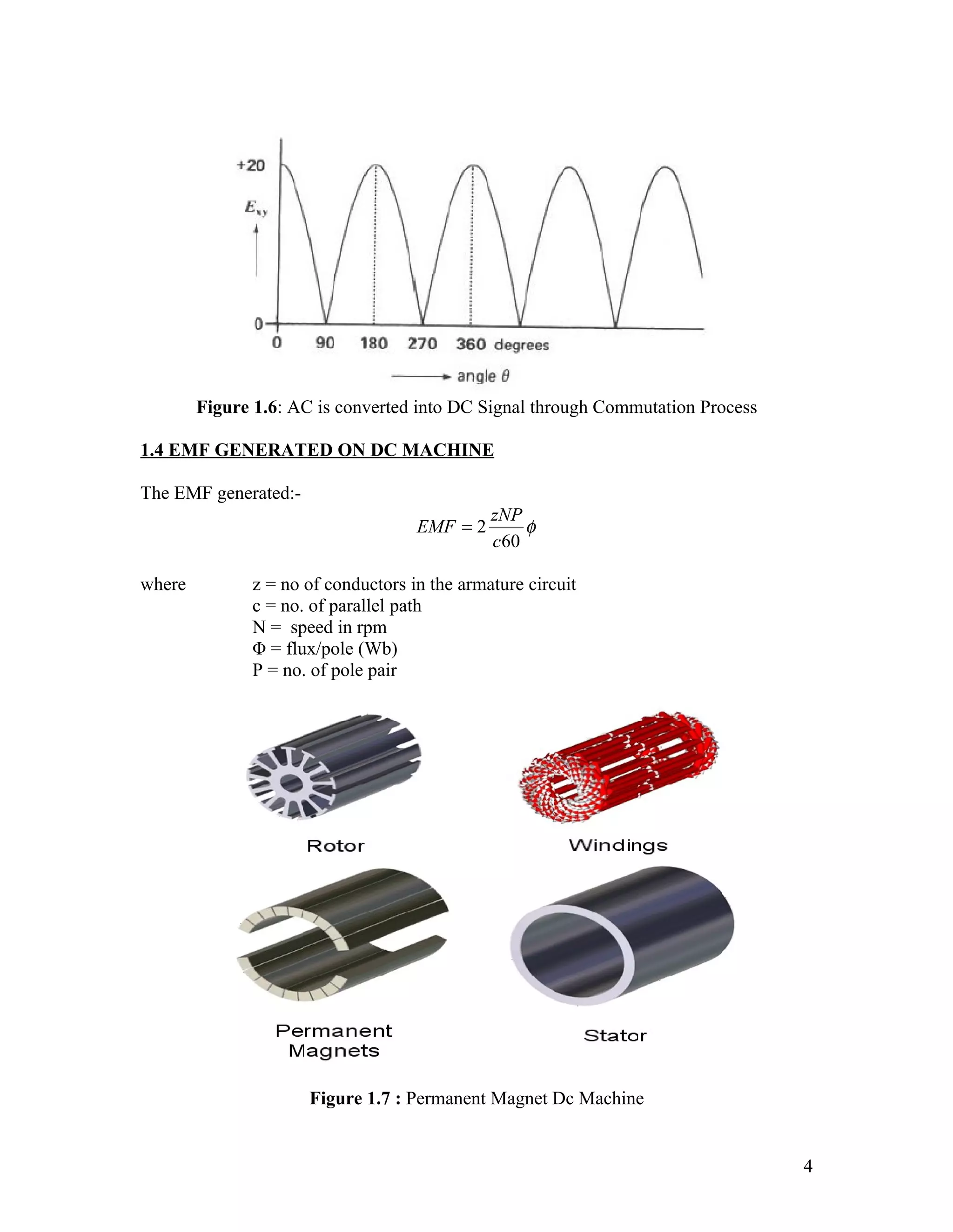
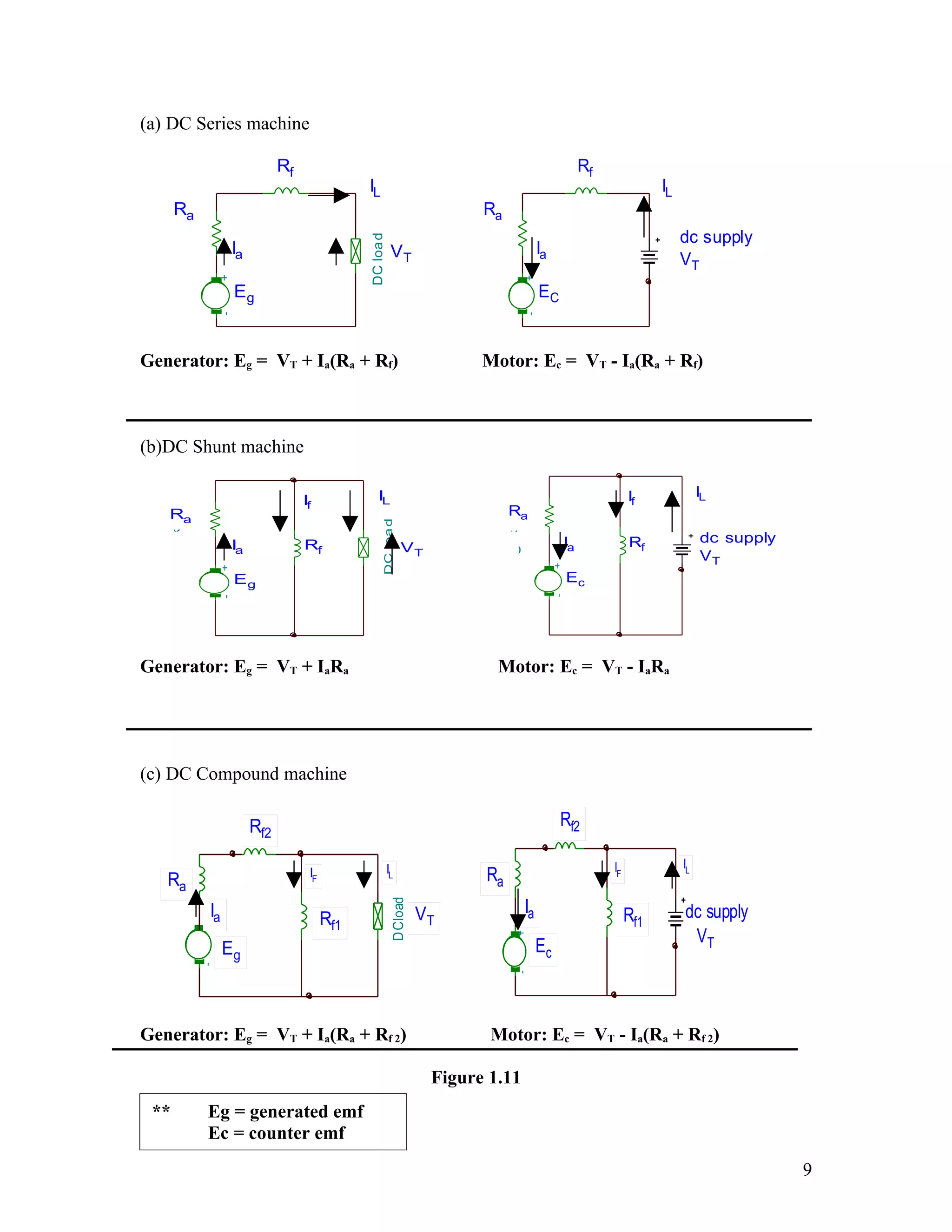

The document discusses DC machines and provides three key points: 1. It introduces DC generators and motors, their basic construction involving a commutator, and advantages of DC machines like adjustable speed control. 2. It explains how a DC generator works by generating an AC signal using a slip ring, and then rectifying it to DC using a commutator. Circuit diagrams and equations for calculating the generated EMF are also provided. 3. It describes different types of DC machine windings including separately excited, series, shunt and compound connections and how these determine the machine's operation as a motor or generator.


![D.c. machine[1]](https://cdn.slidesharecdn.com/ss_thumbnails/d-160420172313-thumbnail.jpg?width=640&height=640&fit=bounds)


![Chapter 4 dc machine [autosaved]](https://cdn.slidesharecdn.com/ss_thumbnails/chapter4-dcmachineautosaved-140915220206-phpapp01-thumbnail.jpg?width=640&height=640&fit=bounds)


