Download as PDF, PPTX


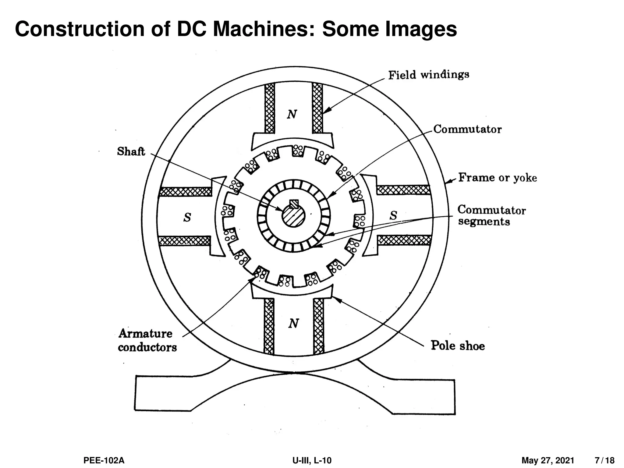


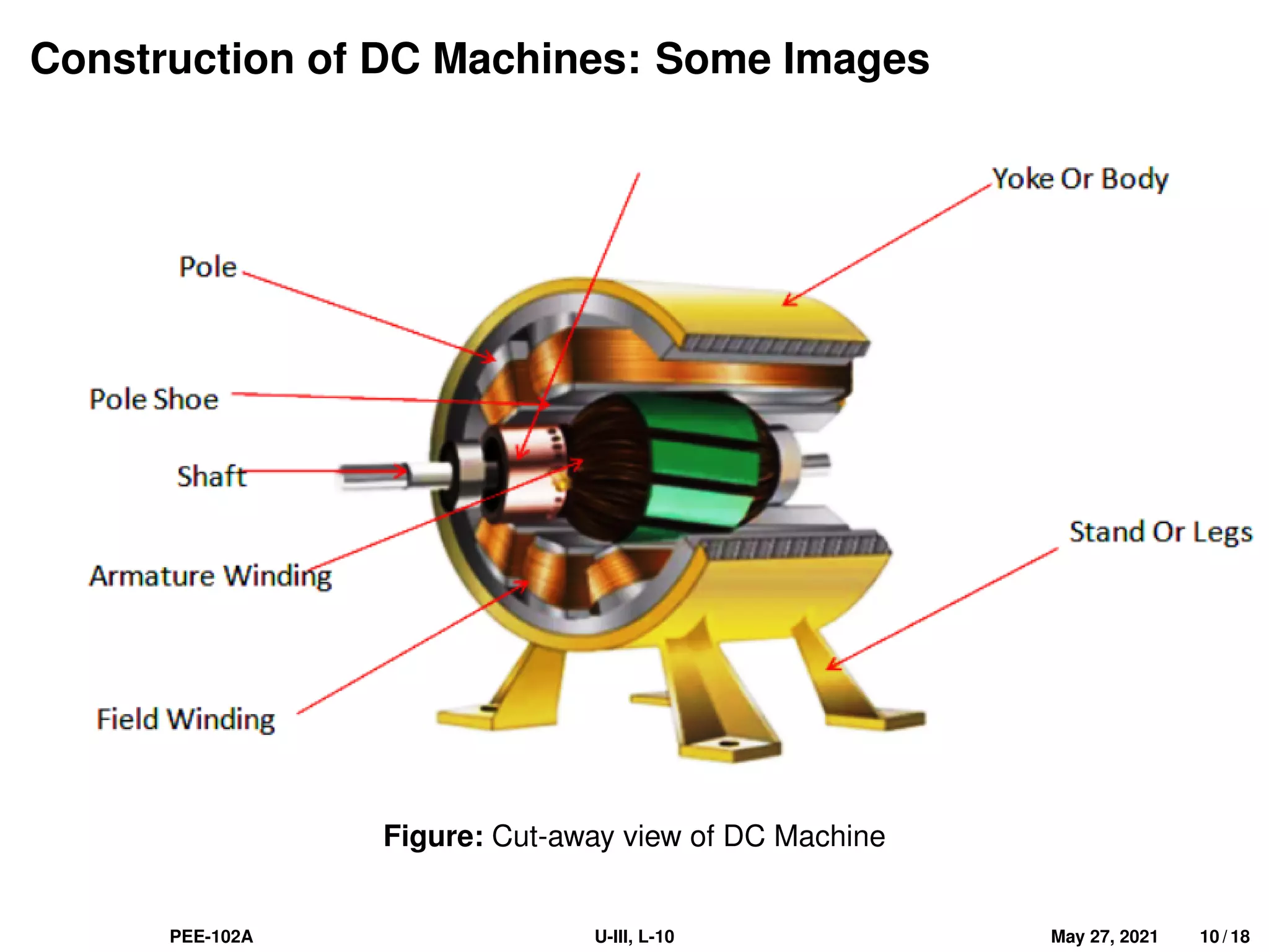


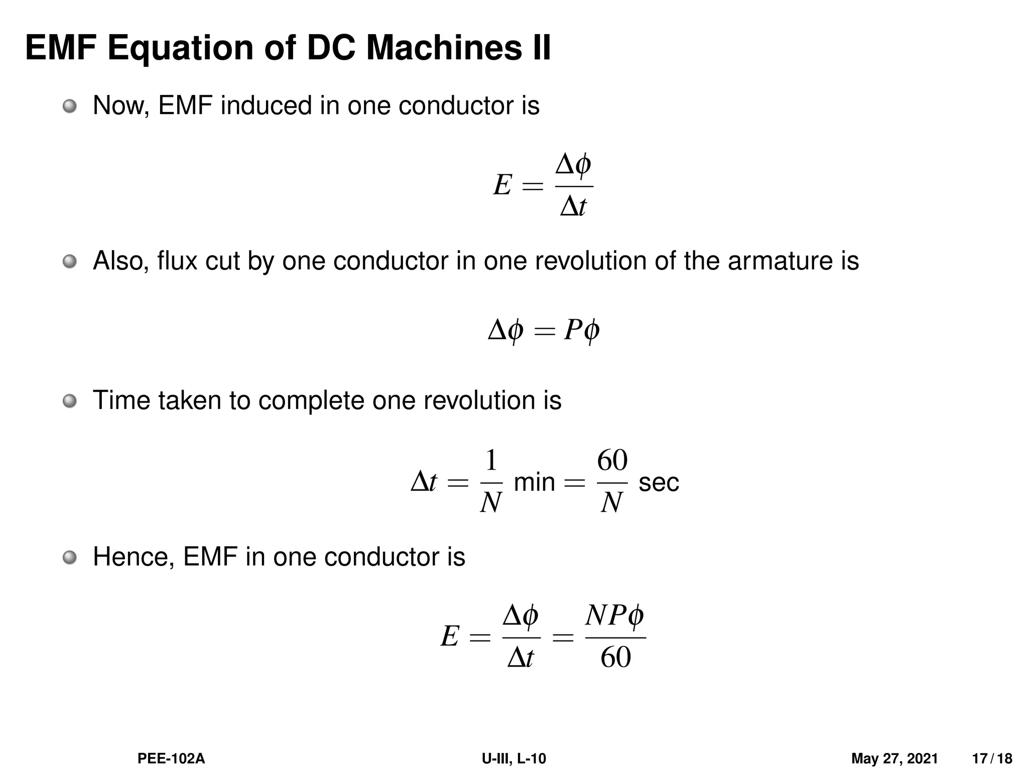
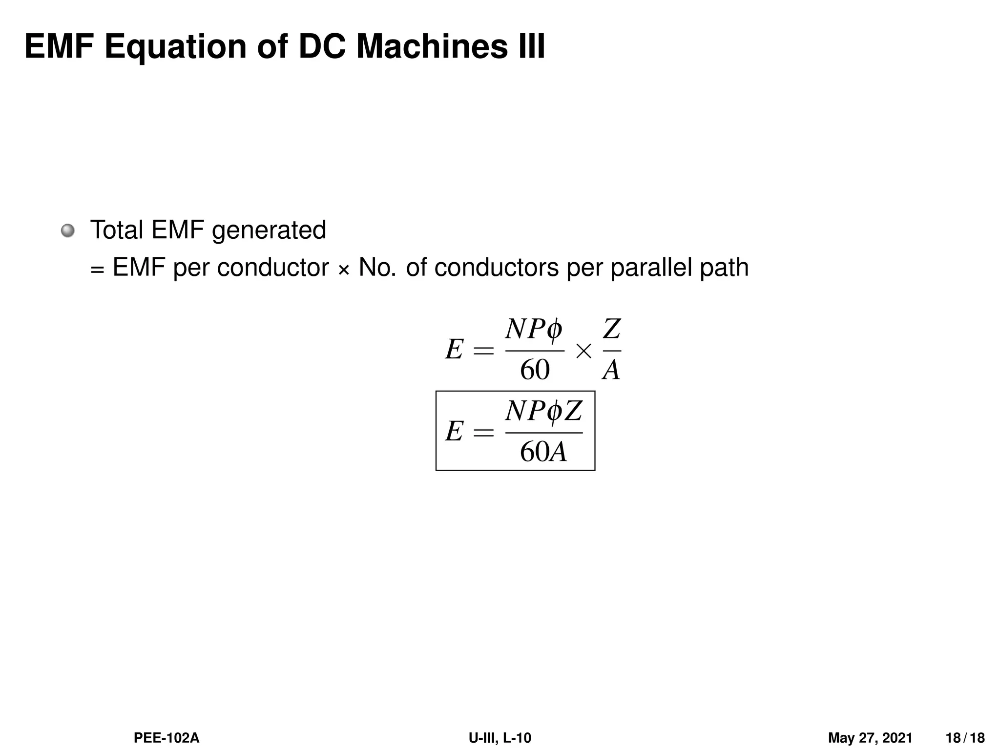


The document discusses the fundamentals of single phase induction motors and DC machines, highlighting that single phase induction motors are not self-starting due to the nature of the magnetic field produced. It details the construction and operation of DC machines, including their main parts: magnetic-field system, armature, and commutator. Additionally, it explains the principle of generating electromotive force (emf) in DC machines, providing a derived equation for emf based on various factors.