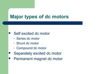
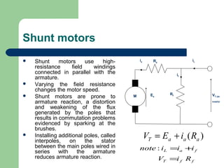
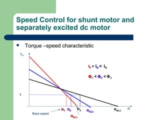
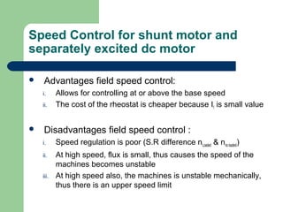
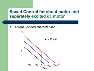
This document discusses direct current (DC) motors. It describes the construction and operating principles of different types of DC motors including series, shunt, compound and permanent magnet motors. It also discusses speed control methods for shunt and separately excited DC motors. The main methods of speed control are armature voltage control, field control and armature resistance control. Armature resistance control is simple but less efficient while field control provides better speed regulation.

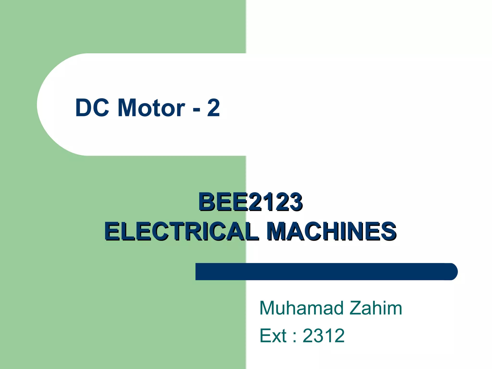
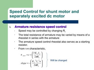
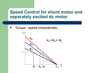
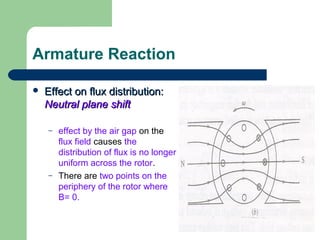
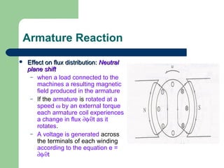
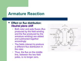
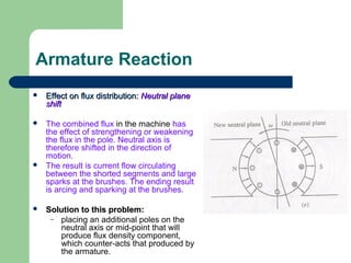
![Series Motor (cont)
Example 1:
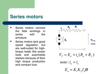
A dc machine in Figure 1 is
consumed a 6.5kW when the
12.5 A of armature current is
passing thru the armature and
field resistance of 3.3Ω and 2.0Ω
respectively. Assume stray
losses of 1.2kW. Calculate
a) terminal voltage, VT
b) back emf, Ea
c) net torque if the speed is at
3560rpm
d) efficiency of the machine
[520V, 453.75V, 12N-m, 68.8%]
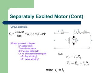
EEaa
RRff
MM VVT (dcT (dc
supply)supply)
RRaaiiaa
Figure 1](https://image.slidesharecdn.com/chapter2-2typesofdcmotor-160130074901/85/Types-of_dc_motor-9-320.jpg)
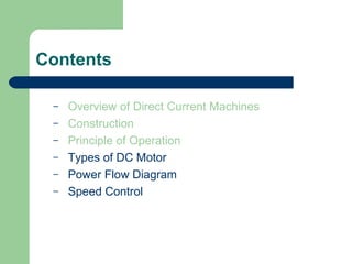
![Series Motor (cont)
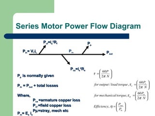
Example 2:
A 600V 150-hp dc machine in
Figure 2 operates at its full rated
load at 600rpm. The armature and
field resistance are 0.12Ω and
0.04Ω respectively. The machine
draws 200A at full load. Assume
stray losses 1700W. Determine
a) the armature back emf at full load,
Ea
b) developed/mechanical power and
developed/mechanical torque
c) assume that a change in load
results in the line current dropping
to 150A. Find the new speed in
rpm and new developed torque.
{Hint: Ea=K1K2iaω}
EEaa
RRff
MM VVT (dcT (dc
supply)supply)
RRaaiiaa
Figure 2
[568V, 113.6kW, 1808Nm, 811.27rpm, 1017Nm]](https://image.slidesharecdn.com/chapter2-2typesofdcmotor-160130074901/85/Types-of_dc_motor-10-320.jpg)

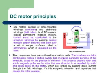
![Shunt Motor
Example :
– A voltage of 230V is applied to armature of a
machines results in a full load armature currents
of 205A. Assume that armature resistance is
0.2Ω. Find the back emf, net power and torque by
assuming the rotational losses are 1445W at full
load speed of 1750rpm.
[189V, 37.3kW, 203.5Nm]](https://image.slidesharecdn.com/chapter2-2typesofdcmotor-160130074901/85/Types-of_dc_motor-13-320.jpg)


![Chapter 4 dc machine [autosaved]](https://cdn.slidesharecdn.com/ss_thumbnails/chapter4-dcmachineautosaved-140915220206-phpapp01-thumbnail.jpg?width=640&height=640&fit=bounds)


