Download to read offline


![Closed loop CBEDC
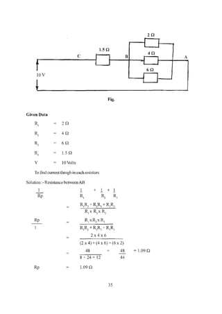
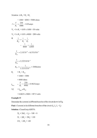
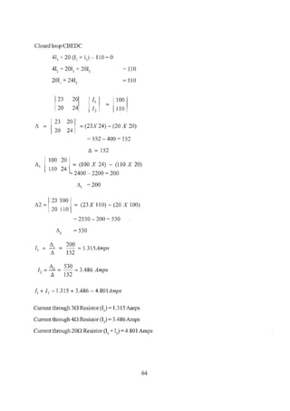
412 + 20(11 + I) - 110 = 0
412 + 2011
+ 2012
= 110
2012
+ 2412 = 110
30
100V 1iOV
100V 110V
F E D
Fig.
[~~~[J
~J
= [:~~]
23 20
,1 = 20 24 = (23X24) - (20X20) = 152
10020
,11 = 110 24 = (1OOX24) - (20Xl1 0) = 200
23 100
,12 = 20 110 =(23XlOO)-(100X20) = 530
II = ~ = 200 = 1.315A
Ll 152
1 = ,12 = 530 = 3.486 A
2 ,1 132
60](https://image.slidesharecdn.com/el-210927092217/85/El-engg-theory-notes-1-book-67-320.jpg)

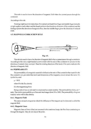
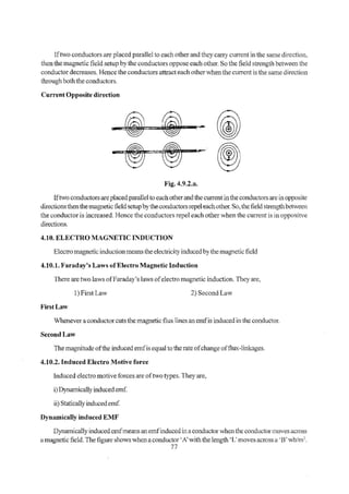


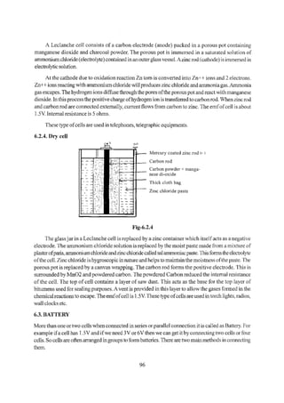


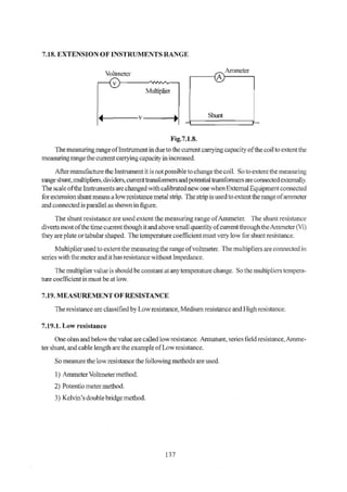
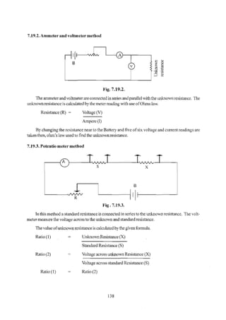
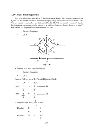
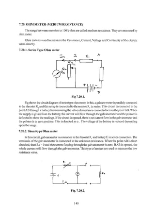


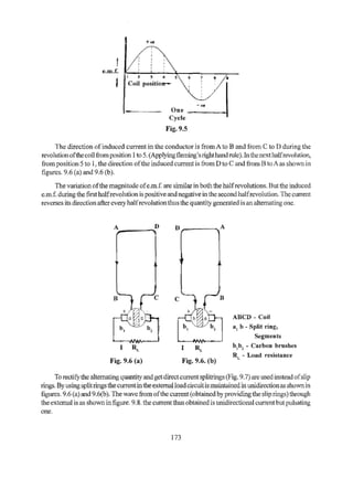
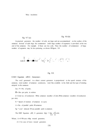
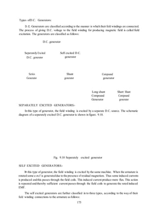
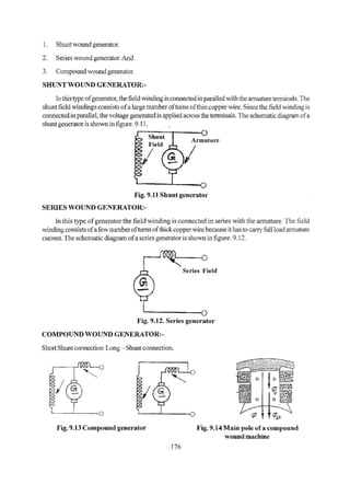


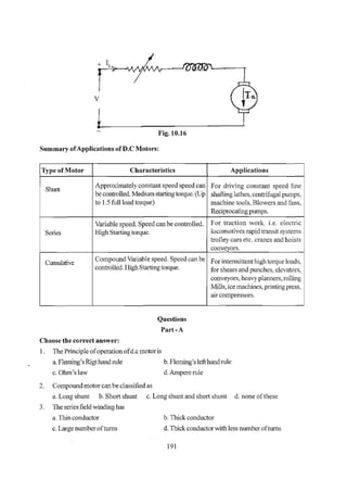


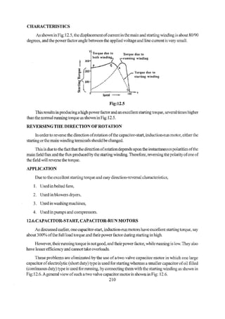

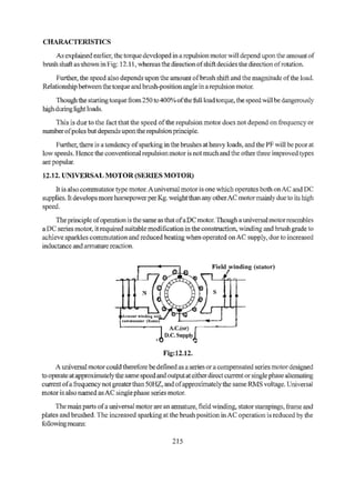
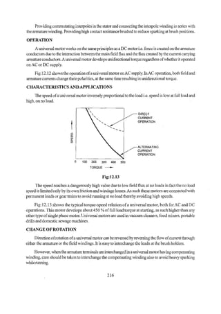
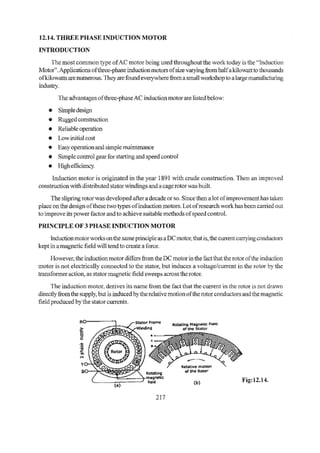
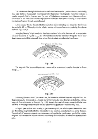


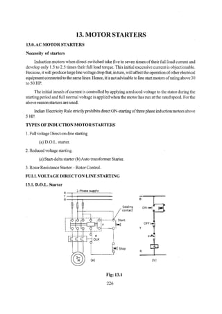
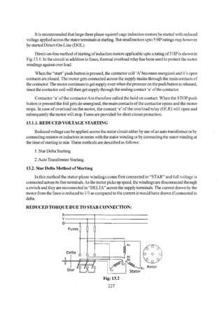
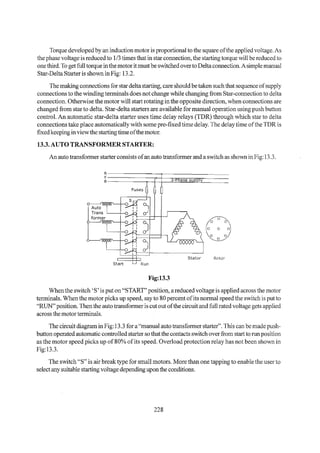
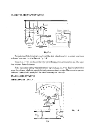
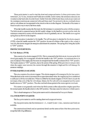


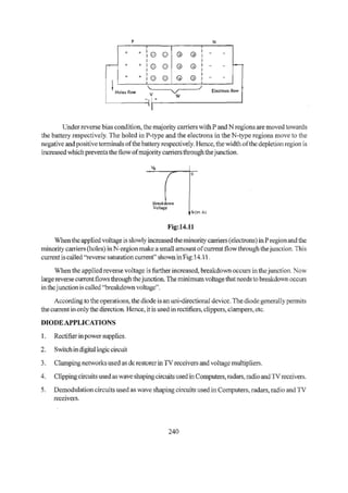
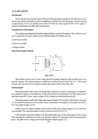
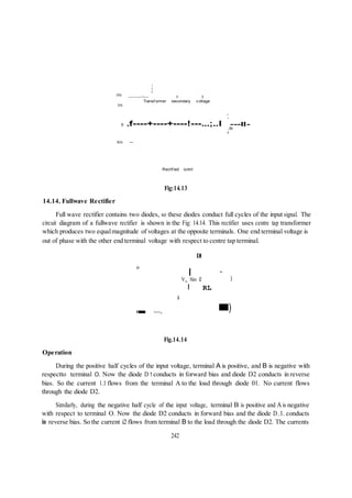
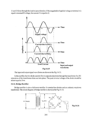
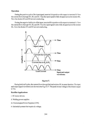

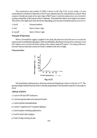
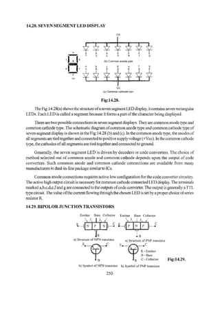
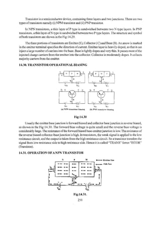
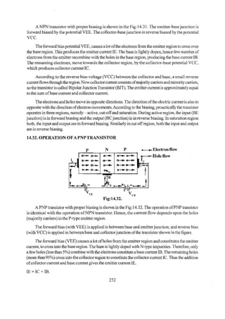
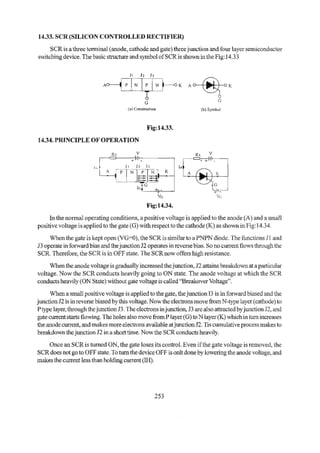


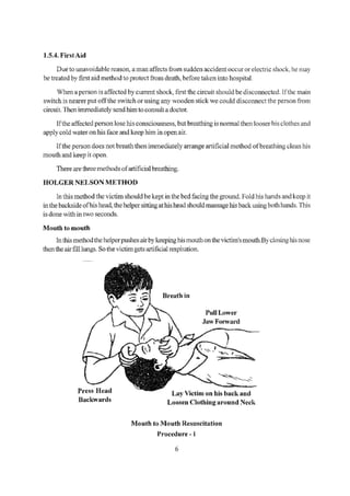
The document discusses different types of AC and DC motor starters and electronics components. For AC motors, it describes DOL starter, star-delta starter, and auto transformer starter. For DC motors, it mentions three point starter and four point starter. It then provides an overview of semiconductor components used in electronics like semiconductors, diodes, transistors, SCRs, LEDs, and basic rectifier circuits.