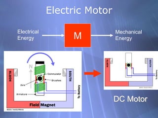
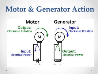
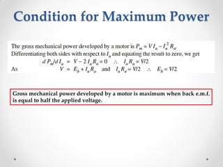
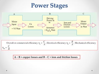
This document discusses electric motors and DC motors specifically. It provides information on:
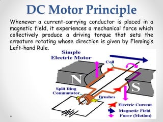
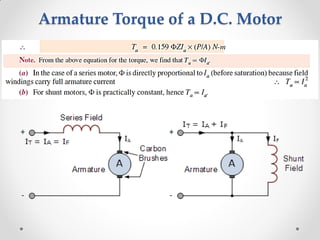
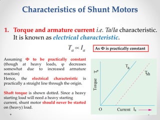
1. The basic components and principles of DC motors, including how a current-carrying coil in a magnetic field produces torque.
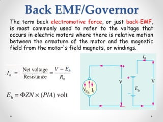
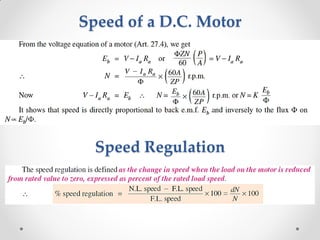
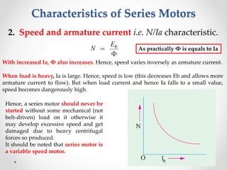
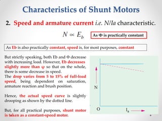
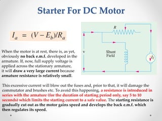
2. How back electromotive force (EMF) regulates motor speed as the armature rotates in the magnetic field.
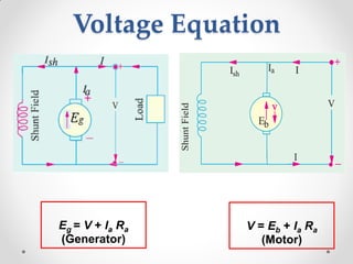
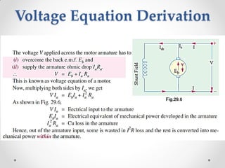
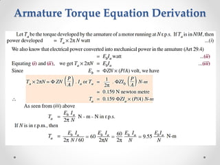
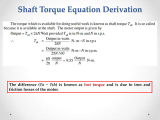
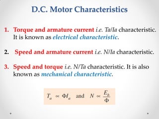
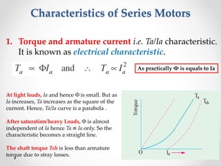
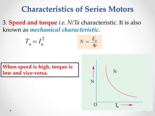
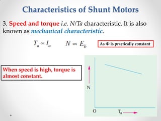
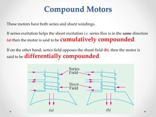
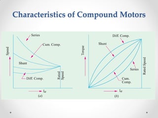
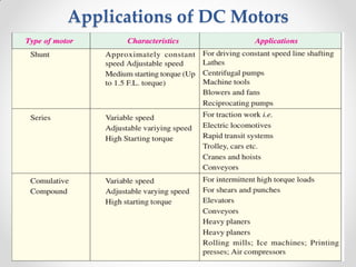
3. Equations for motor voltage, torque, speed, and characteristics like torque-current curves for series, shunt, and compound motors.
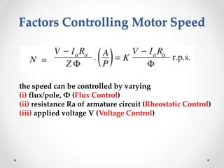
4. Methods for controlling motor speed including changing the flux, armature resistance, or applied voltage. Starters are also discussed to limit starting current.
![Speed Control of DC motors
(ii) Armature or Rheostatic Control Method
This method is used when speeds below the no-load speed are required. As the supply
voltage is normally constant, the voltage across the armature is varied by inserting a
variable rheostat or resistance (called controller resistance) in series with the armature
circuit as shown in Fig. (a).
As controller resistance is increased, potential difference(p.d.) across the armature is
decreased, thereby decreasing the armature speed. For a load constant torque, speed is
approximately proportional to the p.d. across the armature. From the speed/armature
current characteristic [Fig. (b)], it is seen that greater the resistance in the armature
circuit, greater is the fall in the speed.](https://image.slidesharecdn.com/eece259dcmotor-160510181804/85/Eece-259-dc-motor-28-320.jpg)


![D.c. machine[1]](https://cdn.slidesharecdn.com/ss_thumbnails/d-160420172313-thumbnail.jpg?width=640&height=640&fit=bounds)


![Chapter 4 dc machine [autosaved]](https://cdn.slidesharecdn.com/ss_thumbnails/chapter4-dcmachineautosaved-140915220206-phpapp01-thumbnail.jpg?width=640&height=640&fit=bounds)


