Generation of High D.C. Voltage (HVDC generation)RP6997
Generation of high dc voltage using different methods like half wave and full wave rectifier, voltage doubler circuits, voltage multiplier circuits, cockcroft-walton circuits and van de graaff generators.
Generation of High D.C. Voltage (HVDC generation)RP6997
Generation of high dc voltage using different methods like half wave and full wave rectifier, voltage doubler circuits, voltage multiplier circuits, cockcroft-walton circuits and van de graaff generators.
Townsend ’s theory
Introduction
Ionization by collision
Townsend’s current growth equation
Current Growth in the Presence of Secondary Processes
Townsend’s secondary ionization coefficient
Townsend’s Criterion for Breakdown
Breakdown in Electronegative Gases
This directional over current relay employs the principle of actuation of the relay....It has a metallic disc free to rotate between the poles of two...
Disadvantages of corona, radio interference, inductive interference between p...vishalgohel12195
Disadvantages of corona, radio interference, inductive interference between power and communication lines
Introduction
Disadvantages of corona.
Radio interference.
Inductive interference between power and communication lines
A synchronous motor is electrically identical with an alternator or AC generator.
A given alternator ( or synchronous machine) can be used as a motor, when driven electrically.
Some characteristic features of a synchronous motor are as follows:
1. It runs either at synchronous speed or not at all i.e. while running it maintains a constant speed. The only way to change its speed is to vary the supply frequency (because NS=120f/P).
2. It is not inherently self-starting. It has to be run up to synchronous (or near synchronous) speed by some means, before it can be synchronized to the supply.
3. It is capable of being operated under a wide range of power factors, both lagging and leading. Hence, it can be used for power correction purposes, in addition to supplying torque to drive loads.
A frequency meter is an instrument that displays the frequency of a periodic electrical signal. Various types of frequency meters are used. Many are instruments of the deflection type, ordinarily used for measuring low frequencies but capable of being used for frequencies as high as 900 Hz.
Power measurement is a valid technique to measure that how much the power is being transmitted through the entire system.
In this presentation you will estimate and understand the following objectives
Wattmeter as a device
Power measurement techniques
Classical based history
Construction of wattmeter
Working of Wattmeter
Power measurement of direct and indirect way
Power measurement in three phase applications
Applications of Wattmeter
The object of this project is to determine and display the frequency of the input power. This is done by using 8051 microcontroller. The circuit of our designed frequency meter includes 8051 microcontroller, Liquid Crystal Display(LCD), Cathode Ray Oscilloscope(CRO) and variable power supply unit.
Voltmeter & Transformers: Types and Applications.Diksha Prakash
This presentation gives an insight into the various types of voltmeters and transformers that exist. The are both electronic measuring instruments. All the types of voltmeters and transformers have been discussed alogwith numerical examples and their solutions.
LINEAR POTENTIOMETER Potentiometers are electrical devices which are a form of variable resistance.
It consists of a sliding contact which moves over the length of a resistance element. This sliding contact connects to a plunger, which links to the object whose displacement is to be measured.
Referring to the electrical circuit shown here, An input voltage Xt is applied across the whole resistance element, at points A and C. The output voltage, Xi , is measured between the sliding contact at point B and the end of the resistance element at point C. A linear relationship exists between the input voltage Xt, output voltage Xi and the distance BC.
ANGULAR POTENTIOMETER Rotary or angular potentiometers measure angular displacement .
NUMERICAL SIMULATIONS OF HEAT AND MASS TRANSFER IN CONDENSING HEAT EXCHANGERS...ssuser7dcef0
Power plants release a large amount of water vapor into the
atmosphere through the stack. The flue gas can be a potential
source for obtaining much needed cooling water for a power
plant. If a power plant could recover and reuse a portion of this
moisture, it could reduce its total cooling water intake
requirement. One of the most practical way to recover water
from flue gas is to use a condensing heat exchanger. The power
plant could also recover latent heat due to condensation as well
as sensible heat due to lowering the flue gas exit temperature.
Additionally, harmful acids released from the stack can be
reduced in a condensing heat exchanger by acid condensation. reduced in a condensing heat exchanger by acid condensation.
Condensation of vapors in flue gas is a complicated
phenomenon since heat and mass transfer of water vapor and
various acids simultaneously occur in the presence of noncondensable
gases such as nitrogen and oxygen. Design of a
condenser depends on the knowledge and understanding of the
heat and mass transfer processes. A computer program for
numerical simulations of water (H2O) and sulfuric acid (H2SO4)
condensation in a flue gas condensing heat exchanger was
developed using MATLAB. Governing equations based on
mass and energy balances for the system were derived to
predict variables such as flue gas exit temperature, cooling
water outlet temperature, mole fraction and condensation rates
of water and sulfuric acid vapors. The equations were solved
using an iterative solution technique with calculations of heat
and mass transfer coefficients and physical properties.
Forklift Classes Overview by Intella PartsIntella Parts
Discover the different forklift classes and their specific applications. Learn how to choose the right forklift for your needs to ensure safety, efficiency, and compliance in your operations.
For more technical information, visit our website https://intellaparts.com
6th International Conference on Machine Learning & Applications (CMLA 2024)ClaraZara1
6th International Conference on Machine Learning & Applications (CMLA 2024) will provide an excellent international forum for sharing knowledge and results in theory, methodology and applications of on Machine Learning & Applications.
Student information management system project report ii.pdfKamal Acharya
Our project explains about the student management. This project mainly explains the various actions related to student details. This project shows some ease in adding, editing and deleting the student details. It also provides a less time consuming process for viewing, adding, editing and deleting the marks of the students.
Sachpazis:Terzaghi Bearing Capacity Estimation in simple terms with Calculati...Dr.Costas Sachpazis
Terzaghi's soil bearing capacity theory, developed by Karl Terzaghi, is a fundamental principle in geotechnical engineering used to determine the bearing capacity of shallow foundations. This theory provides a method to calculate the ultimate bearing capacity of soil, which is the maximum load per unit area that the soil can support without undergoing shear failure. The Calculation HTML Code included.
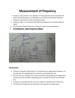
1. Measurement of frequency
Frequency measurement is very important in many application of AC, especially in AC
power systems designed to run efficiently at one and only one particular frequency.
Frequency measurement is done by frequency meter.
Frequency meter is an instrument that displays the frequency of a periodic electrical
signal.
The two types of electrical resonance frequency meter are described below:
I. Ferrodynamic Type Frequency Meter
Construction:
A fixed coil called the magnetizing coil is connected across supply whose frequency is to
be measured. This magnetizing coil is mounted on a laminated iron core.
This iron core has a variable cross-section area which varies gradually over length, being
maximum over the end where magnetizing coil is mounted & minimum over the other
end.
A moving coil is pivoted over this iron core. A pointer is attached to this moving coil.
The terminals of moving coil are connected to the capacitor of suitable value.
2. Operation:
The magnetizing coil carries a current “I” and this current produces a flux “ø”. If we
neglect the resistance &iron losses in the core, flux will be in phase with the current”I”.
Flux”ø” being alternate in nature induces an e.m.f”E” in the moving coil. EMF lags
behind flux by 90°.
The EMF induced causes current “𝐼 𝑚 ” in the moving coil. The phase of this current” 𝐼 𝑚”
depends upon inductance”L” of the moving coil &capacitance “C”.
The operation of instrument can be understood by three phasor diagram:
In Fig.(a)
Crkt. Of the moving coil is assumed to be inductive. So,” 𝐼 𝑚” lags behind “E” by an angle “𝛼”.
So, torque acting on moving coil,
𝑇𝑑 𝛼 𝐼 𝑚 cos(90 + 𝛼).
3. In fig.(b)
Crkt of moving coil is assumed to be largely capacitive “𝐼 𝑚" leads e.m.f “E” by angle𝛽. So,
deflecting Torque
𝑇𝑑 𝛼𝐼 𝑚 cos(90 − 𝛽).
In Fig.(c)
Inductive reactance = capacitive reactance &circuit is under resonance condition. So, moving
coil is purely resistive & so, “𝐼 𝑚 ” is in phase with “E”.
𝑇𝑑 𝛼 𝐼 𝑚 cos(90°) = 0
So, deflecting torque of moving coil is zero when inductive reactance= capacitive reactance.
In actual operation of instrument for a fixed frequency, the capacitive reactance is
constant but inductive reactance of moving coil isn’t constant. This is because
inductance of moving coil depends on the position it occupies on iron core. This
inductance and inductive reactance is maximum when moving coil is close to
magnetizing coil &minimum when it’s on other end.
The value of capacitance is chosen such that moving coil occupies a convenient mean
position on iron core, when frequency is at its normal value. At this position, inductive
reactance=capacitive reactance.
4. When frequency increases above normal value, inductive reactance (𝑋𝑙) becomes larger
than capacitive reactance (𝑋 𝑐) as 𝑋𝑙 𝛼 𝑓 &𝑋 𝑐 𝛼
1
𝑓
. So, a torque is produced, this torque
tries to pull the coil to an equation position where𝑋𝑙 = 𝑋 𝑐.
Therefore, 𝑋𝑙 > 𝑋 𝑐. So, we have to reduce𝑋𝑙. So, moving coil is moved away from
magnetizing coil to reduce𝑋𝑙.
The coil will come to rest at 𝑋𝑙 = 𝑋 𝑐; f=
1
2𝜋√𝐿𝐶
Advantages:
Instrument has great sensitivity.
II. Electrodynamometer Type Frequency Meter
5. There are two parts of fixed coil part1 & part2.
The 2 parts form separate resonance circuit.
Fixed Coil 1 is in series with 𝐿1& 𝐶1form a resonance frequency f1, slightly above
the lower end of instrument scale.
Fixed coil 2 is in series with 𝐿2 & 𝐶2 forms a resonance frequency f2, slightly
higher than upper end of instrument scale.
2 parts of fixed coil having their return circuit through movable coil.
Torque on movable element 𝛼 current in moving coil & this current is sumof
current in 2 parts of fixed coil.
For an applied frequency in frequency range of instrument circuit of fixed coil 1
operates above resonant frequency (𝑋𝑙1 > 𝑋 𝑐1) current𝐼1, through it, lags
applied voltage.
Fixed coil 2 operates below resonant frequency, (𝑋 𝑐2 > 𝑋𝑙2) with current 𝐼2
leads applied voltage.
One current coil is inductive while other current coil is capacitive in nature.
Torque produced by 2 currents I1 &I2 will be in opposition on moving coil. The
resultant torque will be a function of applied frequency of applied voltage & so,
meter scale can be calibrated in terms of frequency.
This meter is used for Power Frequency Measurement.
III. Weston Frequency Meter
6. Consists of 2 coil A & B mounted perpendicular to each other.
Branch circuit of coil A has a resistance 𝑅 𝐴 connected in series with it & coil B has a
reactance 𝐿 𝐵 in series with it.
Coil A is parallel reactance coil𝐿 𝐴.
Coil b is parallel𝑅 𝐵.
Moving element is soft iron needle. This needle is pivoted on a spindle which also
carries a pointer.
The meter is connected across the supply & 2 coils carry current.
These current set up 2 magnetic fields which are at right angles to each other. The
magnitude of field depends upon value of current in coil.
Both these fields act on needle & needle takes up a position which depends upon
relative magnitude of 2 fields.
Metre is so designed that at a normal f,𝐿 𝐴&𝑅 𝐵 sends equal current in coil A&B. so,
needle takes up position which is 45° to both coils and points at center of scale.
Now, if frequency increase above normal value (𝐿 𝐴 & 𝐿 𝐵) increase & (𝑅 𝐴 & 𝑅 𝐵) remain
same.
Coil A is parallel𝐿 𝐴.
Coil B is parallel𝑅 𝐵.
As, f increases, 𝐿 𝐴increases,V in coil A increases, I in coil A increases. While I in coil B
decreases. So, magnetic field of coil A is stronger than that of B.
Tendency of needle to deflect towards stronger field. So, it tends to set itself in line with
coil axis A. so, pointer deflects to left.
When f decreases then opposite action takes place &pointer deflects to right.
7. IV. Ratiometer Type Frequency Meter
Ratiometer type frequency meter consist of a ratiometer which gives linear relationship
between current ration & deflection.
The 2 coils of this ratiometer are fed with rectified output currents of 2 separate bridge
rectifier.
The input sides of 2 bridge rectifier are connected to alternating current supply whose
frequency is to be measured.
The input side of one of bridge rectifier has a series capacitance “C” &other has series
resistance”R”.
Let, V be the supply voltage &” f” be supply frequency
Output of bridge rectifier 1 is:
𝐼1 𝛼 𝐼𝐶 𝛼 𝑓𝑉𝐶
Output of bridge rectifier 2 is:
𝐼2 𝛼 𝐼 𝑅 𝛼
𝑉
𝑅
Ratiometer,
8. Deflection (𝜃)
=𝐾
𝐼1
𝐼 2
=K
2𝜋𝑓𝑉𝐶
𝑉
𝑅
= 2𝜋𝐾1 𝐶𝑅𝐹
𝐾1, 𝐶, 𝑅 𝑎𝑟𝑒 𝑐𝑜𝑛𝑠𝑡𝑎𝑛𝑡
𝜃 = 𝐾2F
Instrument has a linear scale of frequency ratiometer is so designed that deflection (𝜃)
𝛼 ratio of two current.
Advantage:
Supply voltage (V) dosen’t appears in expression of deflection (𝜃). Hence, this
instrument can be used fairly for wide range of voltage.
Saturable Core Frequency Meter
This meter has a saturable core transformer as its primary detector.
The deflection of meter is 𝛼 frequency to be measured.
These frequency meter have the advantage that it can measure frequencies over a wide
range & is well suited especially for use I tachometer systems.