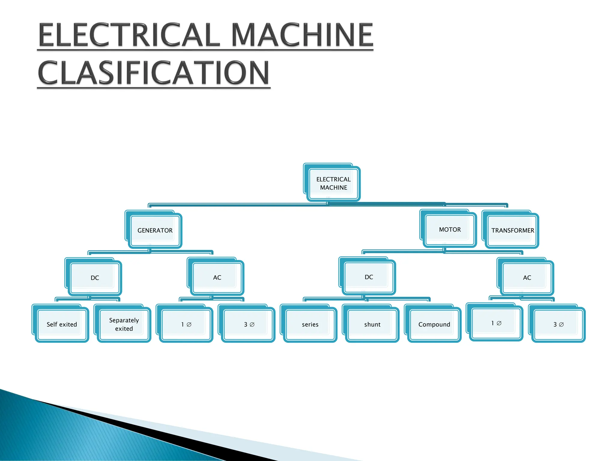
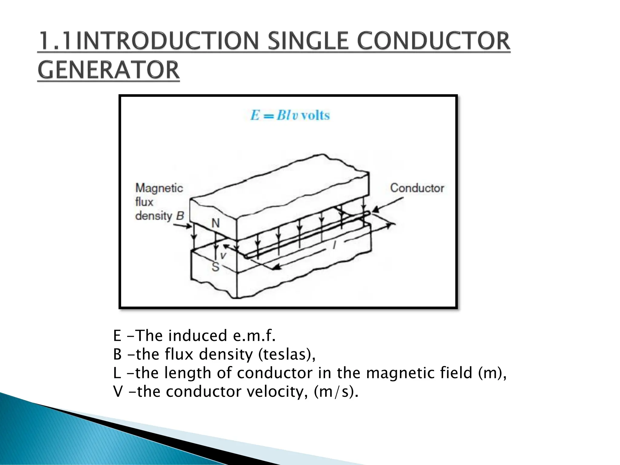
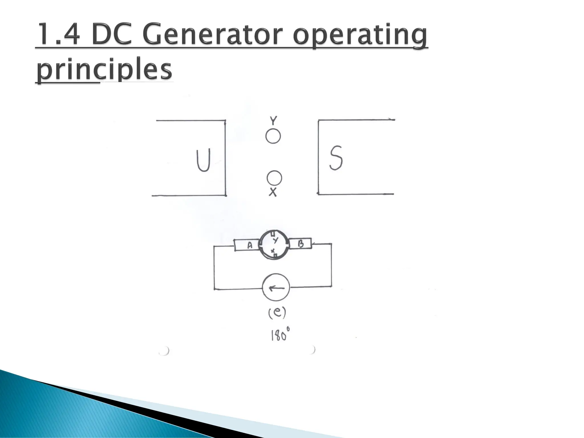
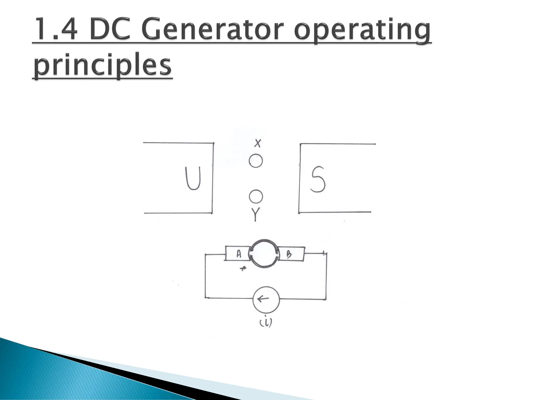
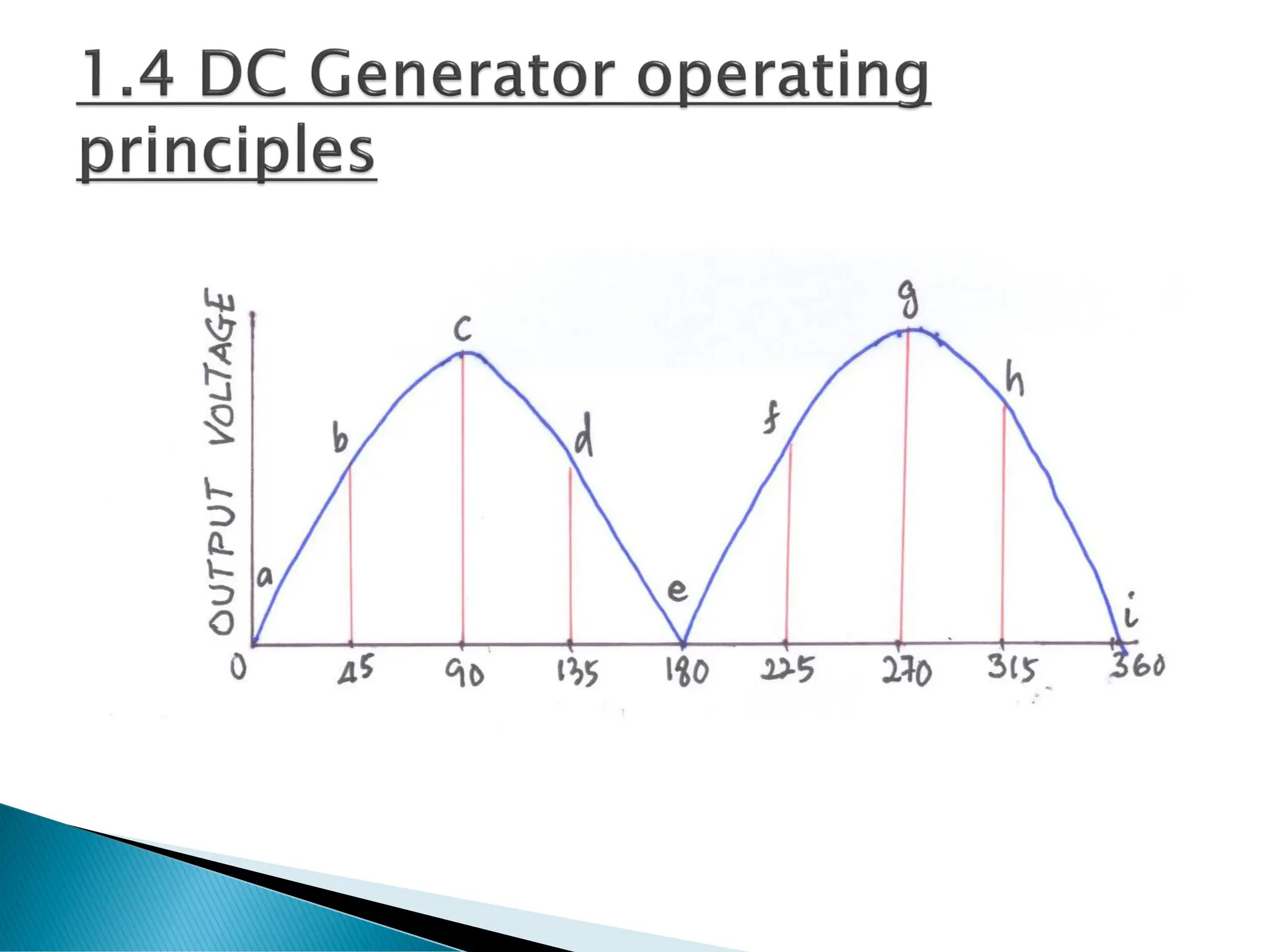
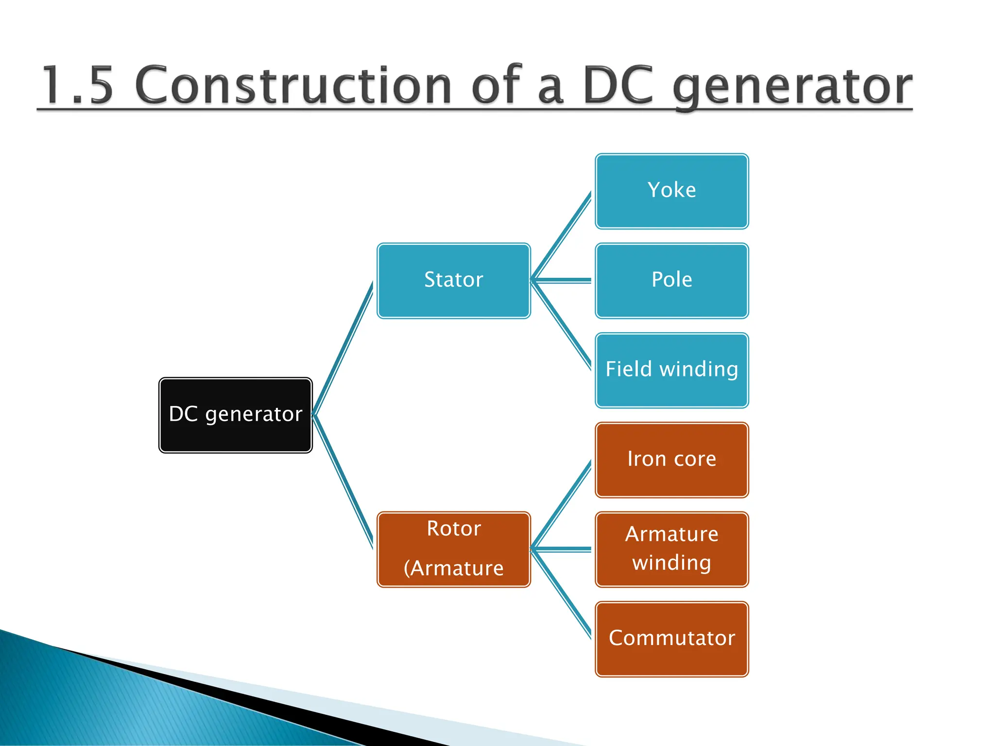
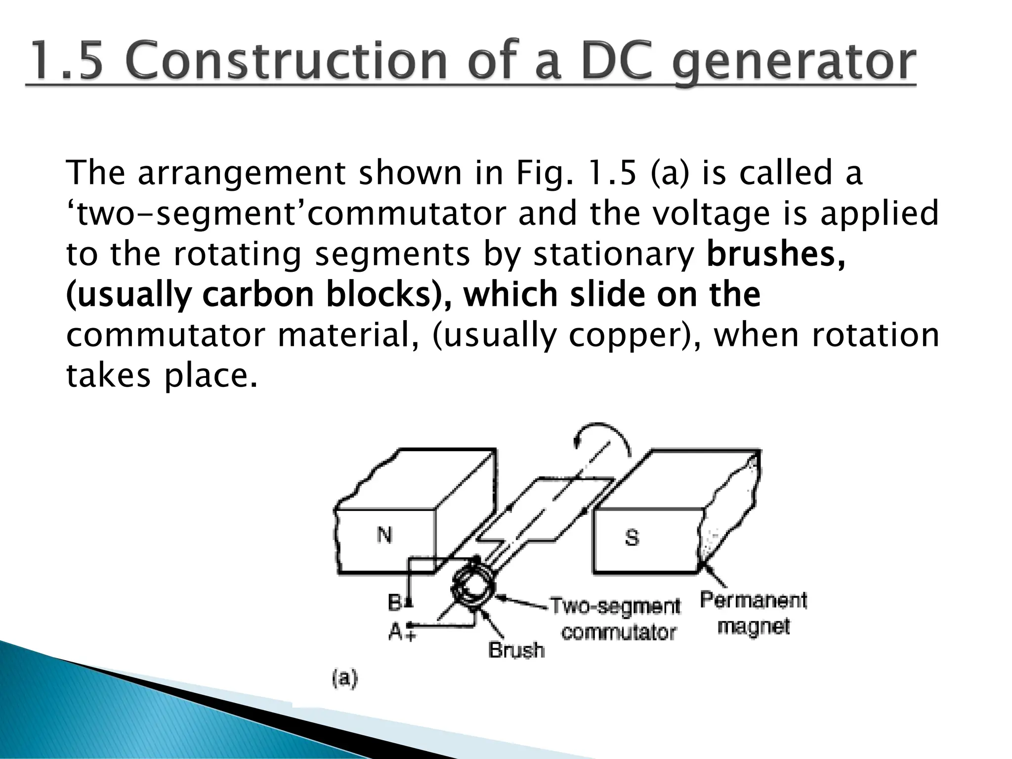
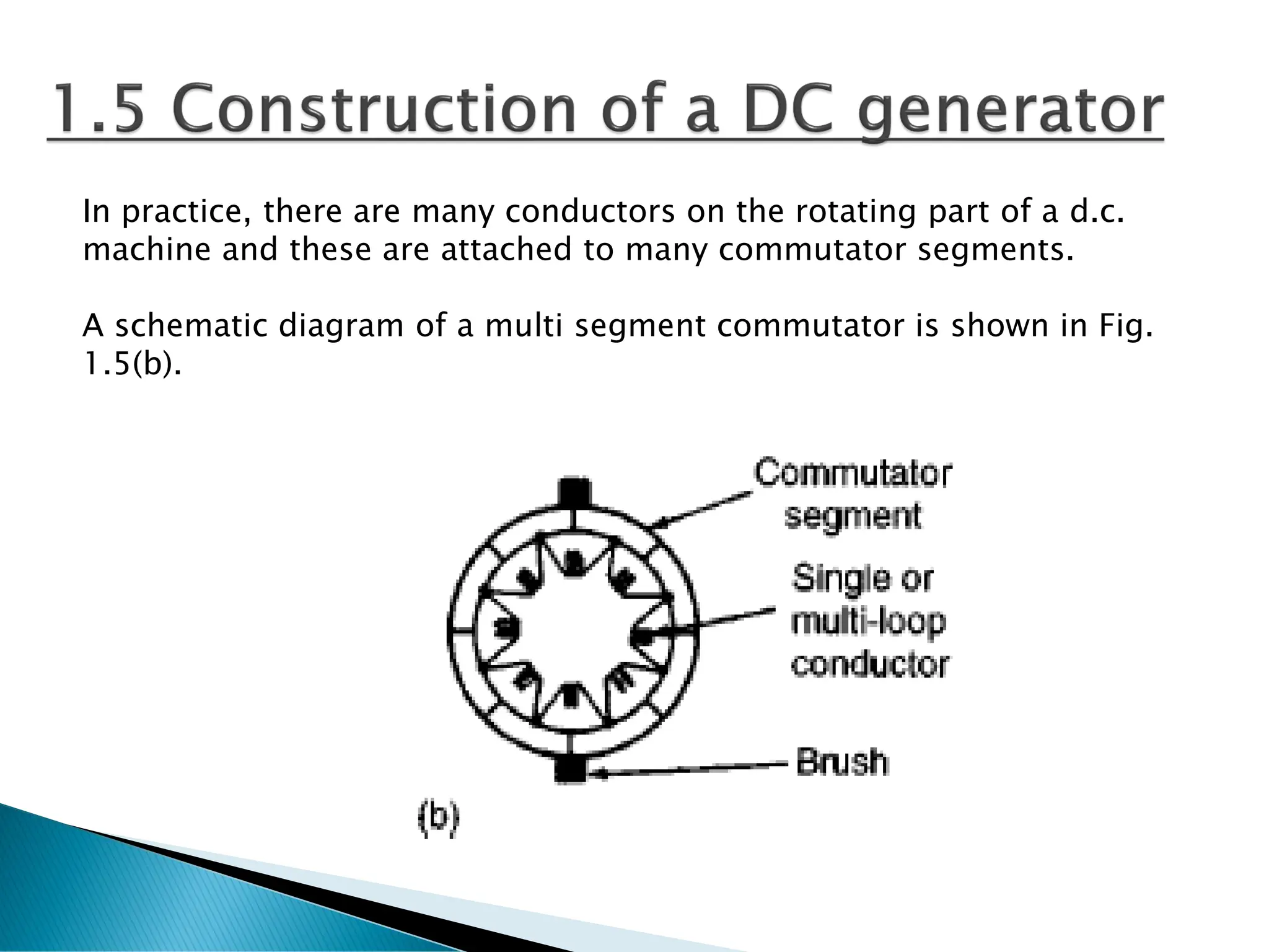
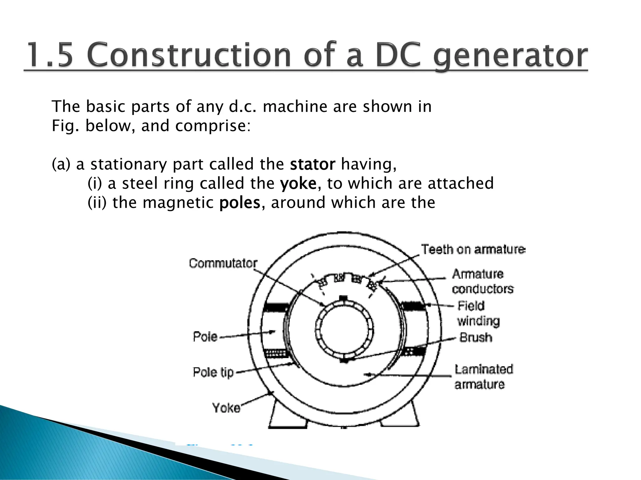
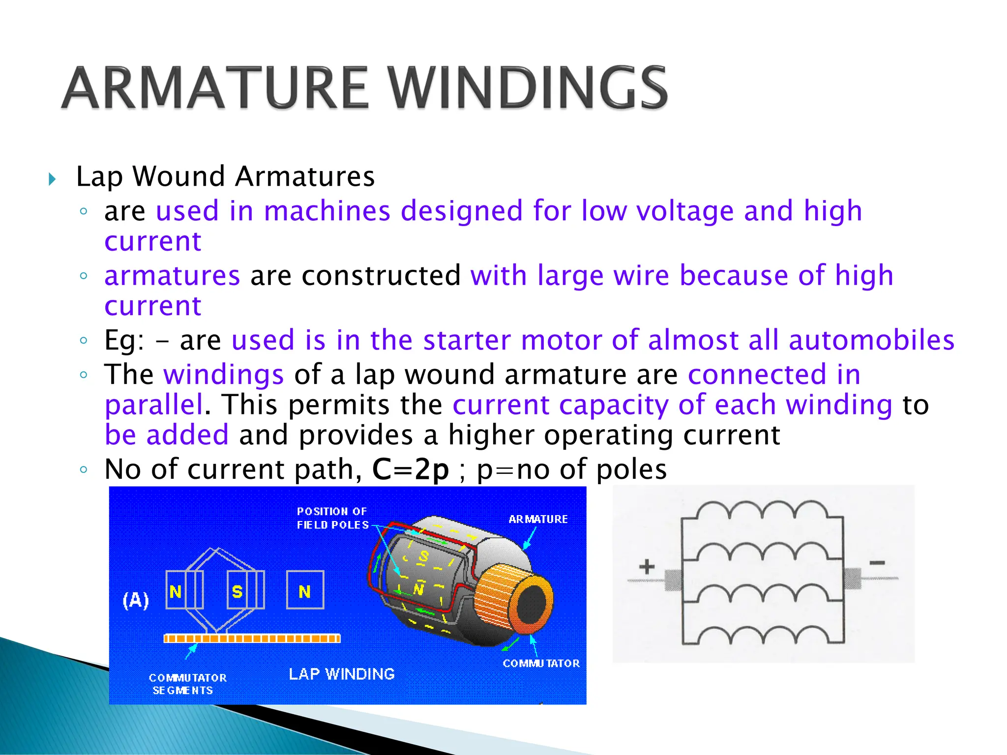
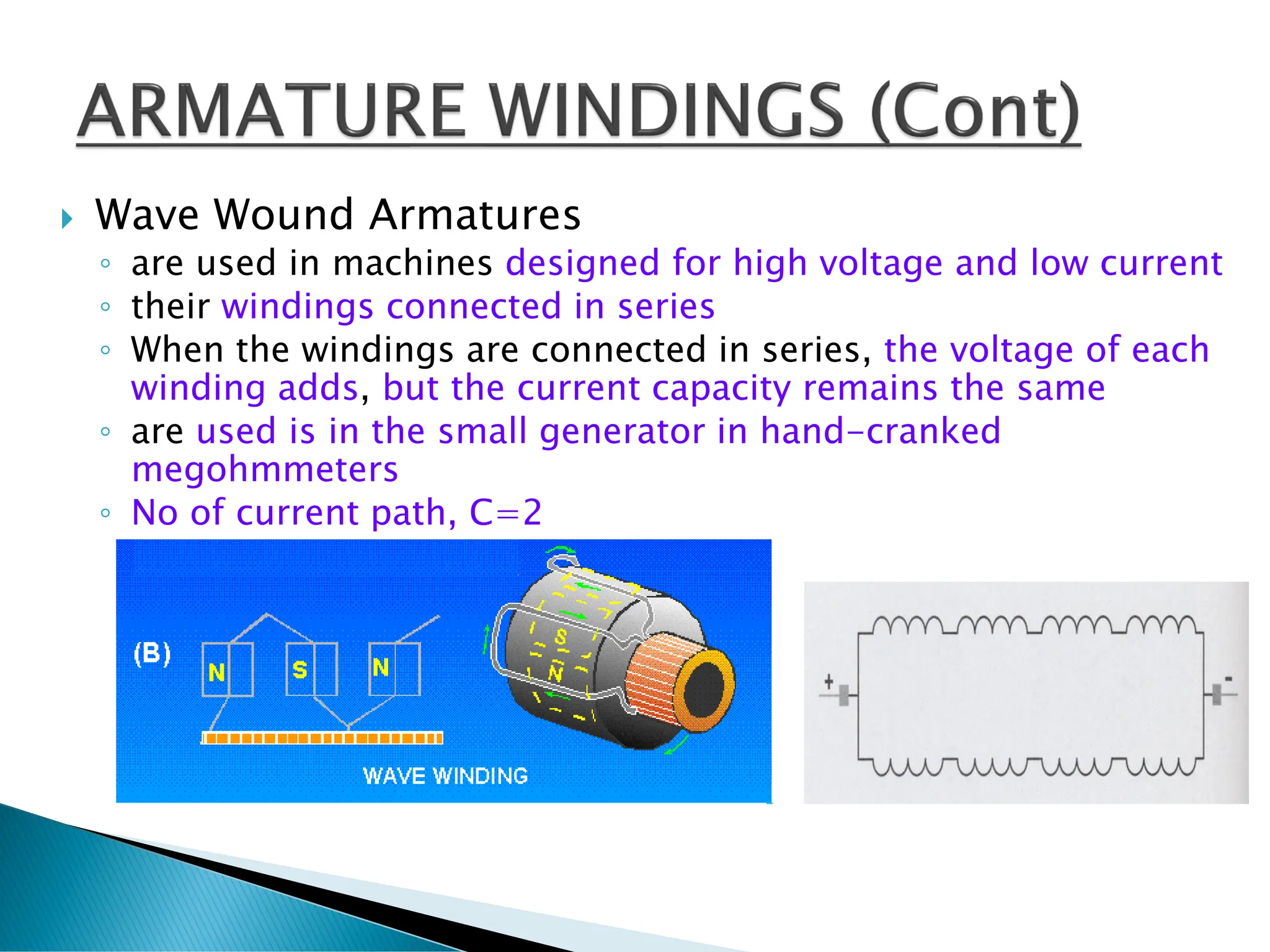
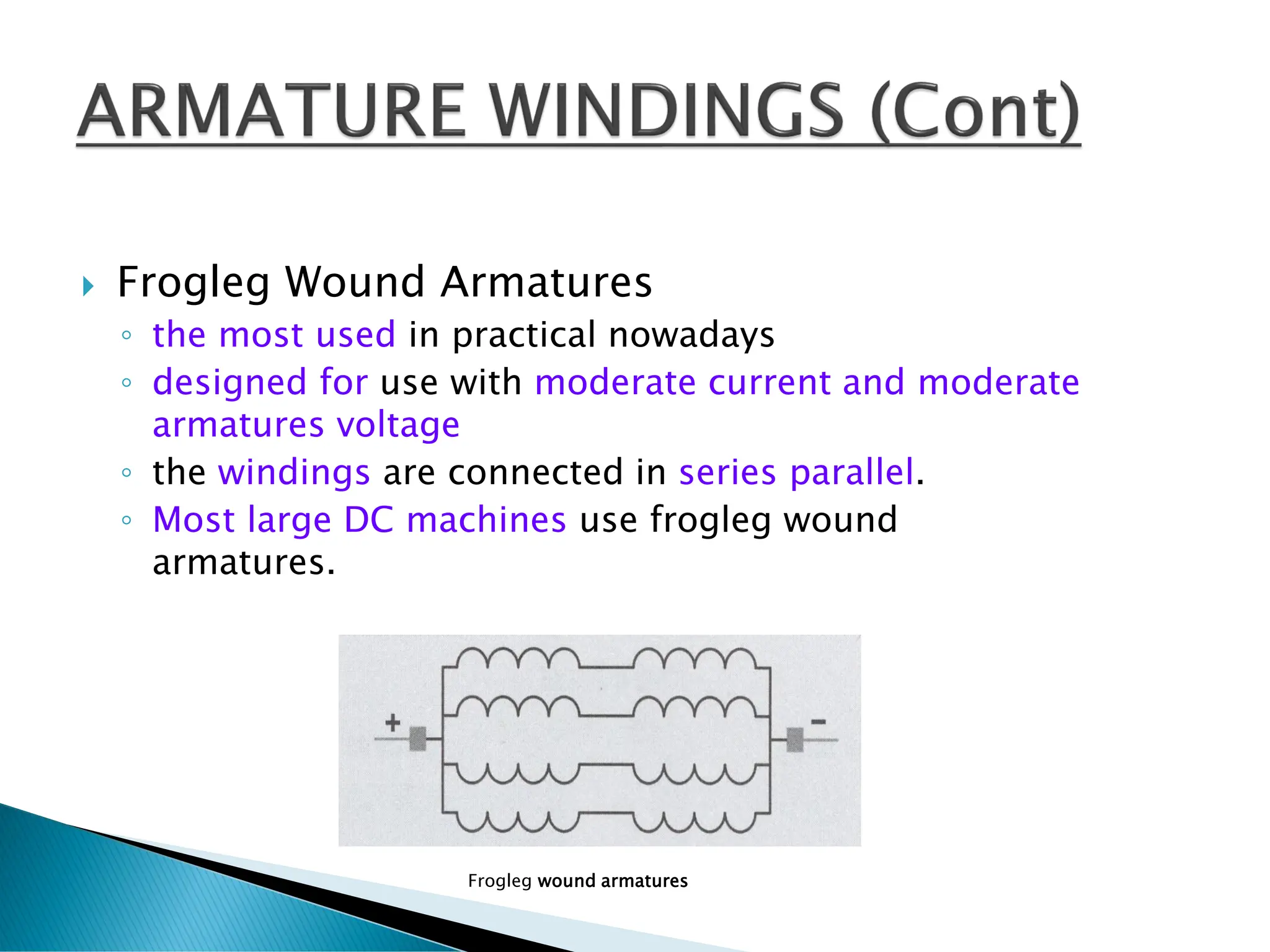
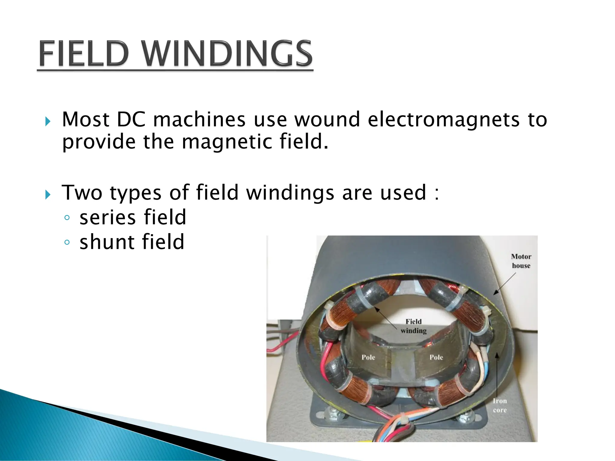
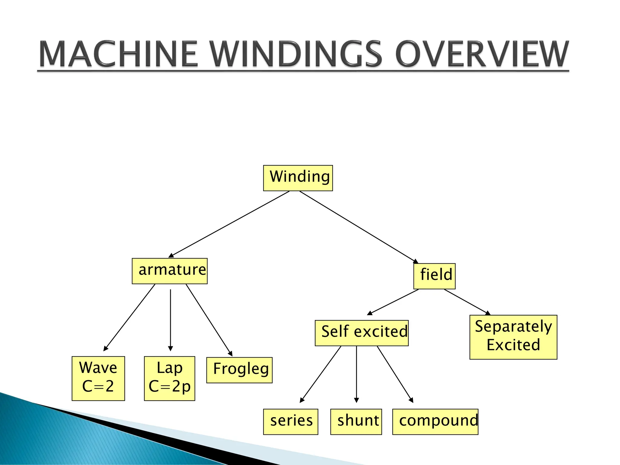
BAB 1- DC GENERATOR
ELECTRICAL
MACHINE
GENERATOR
DC
Self exited
Separately
exited
AC
1  3 
MOTOR
DC
series shunt Compound
AC
1  3 
TRANSFORMER
 In a generator, conductors forming an electric
circuit are made to move through a magnetic
field.
 By Faraday’s law an e.m.f. is induced in the
conductors and thus a source of e.m.f. is
created.
 A generator converts mechanical energy into
electrical energy
E -The induced e.m.f.
B -the flux density (teslas),
L -the length of conductor in the magnetic field (m),
V -the conductor velocity, (m/s).
Fleming’s Right-hand rule
(often called the geneRator rule)
which states:
Let the thumb, first finger and
second finger of the
right hand be extended such that
they are all at right
angles to each other (as shown in
Figure). If the first
finger points in the direction of the
magnetic field and the
thumb points in the direction of
motion of the conductor
relative to the magnetic field, then
the second finger will
point in the direction of the induced
e.m.f.
If the conductor moves at an angle θ◦ to the
magnetic field (instead of at 90◦ as assumed
above) then
E=Blv sin θ volts
The left-hand side is moving in
an upward direction
(check using Fleming’s right-
hand rule), with length l
cutting the lines of flux which
are travelling from left to
right. By definition, the induced
e.m.f. will be equal to
Blv sin θ and flowing into the
page
The right-hand side is moving
in a downward direction
(again, check using Fleming’s
right-hand rule),
with length l cutting the same
lines of flux as above.
The induced e.m.f. will also be
equal to Blv sin θ but
flowing out of the page.
Therefore the total e.m.f. for the loop conductor
=2Blv sin θ
Now consider a coil made up of a number of turns N
The total e.m.f. E for the loop conductor is now given by:
E = 2NBlv sin θ
Problem 1.
A rectangular coil of sides 12 cm and 8 cm is rotated in a magnetic
field of flux density1.4T, the longer side of the coil actually cutting
this flux. The coil is made up of 80 turns and rotates at
1200 rev/min.
(a) Calculate the maximum generated e.m.f.
(b) If the coil generates 90 V, at what speed will the coil rotate?
b) Since E =2NBlv sin θ
The action of a commutator
DC generator
Stator
Yoke
Pole
Field winding
Rotor
(Armature
Iron core
Armature
winding
Commutator
The arrangement shown in Fig. 1.5 (a) is called a
‘two-segment’commutator and the voltage is applied
to the rotating segments by stationary brushes,
(usually carbon blocks), which slide on the
commutator material, (usually copper), when rotation
takes place.
In practice, there are many conductors on the rotating part of a d.c.
machine and these are attached to many commutator segments.
A schematic diagram of a multi segment commutator is shown in Fig.
1.5(b).
Poor commutation results in sparking at the trailing
edge of the brushes.
This can be improved by using interpoles (situated between each
pair of main poles), high resistance brushes, or using brushes
spanning several commutator segments
The basic parts of any d.c. machine are shown in
Fig. below, and comprise:
(a) a stationary part called the stator having,
(i) a steel ring called the yoke, to which are attached
(ii) the magnetic poles, around which are the
(iii) field windings, i.e. many turns of a conductor wound round
the pole core; current passing through this conductor creates an
electromagnet
(b) a rotating part called the armature mounted in bearings housed in
the stator and having
(iv) a laminated cylinder of iron or steel called the core, on
which teeth are cut to house the
(v) armature winding, i.e. a single or multiloop
conductor system, and
(vi) the commutator
Rotor of a dc motor Stator with poles visible.
Construction of DC
machine
Stator: non-moving coil
Rotor: rotating part
Armature coil
Brushes
Rotor is the rotating part -
armature
Stator is the stationary part - field
 More loops of wire = higher rectified voltage
 In practical, loops are generally placed in slots of an iron core
 The iron acts as a magnetic conductor by providing a low-reluctance path for magnetic
lines of flux to increase the inductance of the loops and provide a higher induced
voltage.
 The commutator is connected to the slotted iron core.
 The entire assembly of iron core, commutator, and windings is called the armature.
 The windings of armatures are connected in different ways depending on the
requirements of the machine.
Loops of wire are wound around slot in a metal core DC machine armature
 Lap Wound Armatures
◦ are used in machines designed for low voltage and high
current
◦ armatures are constructed with large wire because of high
current
◦ Eg: - are used is in the starter motor of almost all automobiles
◦ The windings of a lap wound armature are connected in
parallel. This permits the current capacity of each winding to
be added and provides a higher operating current
◦ No of current path, C=2p ; p=no of poles
 Wave Wound Armatures
◦ are used in machines designed for high voltage and low current
◦ their windings connected in series
◦ When the windings are connected in series, the voltage of each
winding adds, but the current capacity remains the same
◦ are used is in the small generator in hand-cranked
megohmmeters
◦ No of current path, C=2
 Frogleg Wound Armatures
◦ the most used in practical nowadays
◦ designed for use with moderate current and moderate
armatures voltage
◦ the windings are connected in series parallel.
◦ Most large DC machines use frogleg wound
armatures.
Frogleg wound armatures
 Most DC machines use wound electromagnets to
provide the magnetic field.
 Two types of field windings are used :
◦ series field
◦ shunt field
 Series field windings
◦ are so named because they are connected in series with the armature
◦ are made with relatively few windings turns of very large wire and have a
very low resistance
◦ usually found in large horsepower machines wound with square or
rectangular wire.
◦ The use of square wire permits the windings to be laid closer together,
which increases the number of turns that can be wound in a particular
space
Square wire permits more turns than round wire in the same area
Square wire contains more surface than round wire
– Square and rectangular wire can also be made physically smaller
than round wire and still contain the same surface area
 Shunt field windings
◦ is constructed with relatively many turns of small wire,
thus, it has a much higher resistance than the series field.
◦ is intended to be connected in parallel with, or shunt, the
armature.
◦ high resistance is used to limit current flow through the
field.
 When a DC machine uses both series and shunt fields, each
pole piece will contain both windings.
 The windings are wound on the pole pieces in such a manner
that when current flows through the winding it will produce
alternate magnetic polarities.
Winding
Lap
C=2p
Wave
C=2
Separately
Excited
Frogleg
Self excited
armature field
series shunt compound
 The magnetic field produced by the stator poles induces
a voltage in the rotor (or armature) coils when the
generator is rotated.
 This induced voltage is represented by a voltage source.
 The stator coil has resistance, which is connected in
series.
 The pole flux is produced by the DC excitation/field
current, which is magnetically coupled to the rotor
 The field circuit has resistance and a source
 The voltage drop on the brushes represented by a
battery
DC Machine Equivalent Circuit
1. Permanent magnet
2. Separately excited
3. Self-excited
DC Machine Equivalent Circuit
1. Permanent magnet
• The poles are made of permanent magnets.
• No field winding required.
• Small size.
• Disadvantage is low flux density, so low torque.
DC Machine Equivalent Circuit
2. Separately excited
The field flux is derived from a separate power source
independent of the generator itself.
B
Field
winding
Armature
winding
DC Machine Equivalent Circuit
3. Self-excited
• Shunt machine
The field flux is derived
by connecting the field
directly across the
terminals of the
generator.
B
DC Machine Equivalent Circuit
3. Self-excited
Series machine
• field are connected
in series with
armature
B
DC Machine Equivalent Circuit
3. Self-excited
• Cumulatively compounded
• Differentially compounded
B
B
B
B
DC Machine Equivalent Circuit
3. Self-excited
Compounded dc generator
• both a shunt and a series field
are present
DC Machine Equivalent Circuit
Compounded dc motor
• both a shunt and a
series field are present
3. Self-excited

Direct Current Generator For University Student

  • 1.
    BAB 1- DCGENERATOR
  • 2.
    ELECTRICAL MACHINE GENERATOR DC Self exited Separately exited AC 1 3  MOTOR DC series shunt Compound AC 1  3  TRANSFORMER
  • 3.
     In agenerator, conductors forming an electric circuit are made to move through a magnetic field.  By Faraday’s law an e.m.f. is induced in the conductors and thus a source of e.m.f. is created.  A generator converts mechanical energy into electrical energy
  • 4.
    E -The inducede.m.f. B -the flux density (teslas), L -the length of conductor in the magnetic field (m), V -the conductor velocity, (m/s).
  • 5.
    Fleming’s Right-hand rule (oftencalled the geneRator rule) which states: Let the thumb, first finger and second finger of the right hand be extended such that they are all at right angles to each other (as shown in Figure). If the first finger points in the direction of the magnetic field and the thumb points in the direction of motion of the conductor relative to the magnetic field, then the second finger will point in the direction of the induced e.m.f.
  • 6.
    If the conductormoves at an angle θ◦ to the magnetic field (instead of at 90◦ as assumed above) then E=Blv sin θ volts
  • 8.
    The left-hand sideis moving in an upward direction (check using Fleming’s right- hand rule), with length l cutting the lines of flux which are travelling from left to right. By definition, the induced e.m.f. will be equal to Blv sin θ and flowing into the page
  • 9.
    The right-hand sideis moving in a downward direction (again, check using Fleming’s right-hand rule), with length l cutting the same lines of flux as above. The induced e.m.f. will also be equal to Blv sin θ but flowing out of the page. Therefore the total e.m.f. for the loop conductor =2Blv sin θ
  • 10.
    Now consider acoil made up of a number of turns N The total e.m.f. E for the loop conductor is now given by: E = 2NBlv sin θ
  • 11.
    Problem 1. A rectangularcoil of sides 12 cm and 8 cm is rotated in a magnetic field of flux density1.4T, the longer side of the coil actually cutting this flux. The coil is made up of 80 turns and rotates at 1200 rev/min. (a) Calculate the maximum generated e.m.f. (b) If the coil generates 90 V, at what speed will the coil rotate?
  • 13.
    b) Since E=2NBlv sin θ
  • 14.
    The action ofa commutator
  • 25.
  • 26.
    The arrangement shownin Fig. 1.5 (a) is called a ‘two-segment’commutator and the voltage is applied to the rotating segments by stationary brushes, (usually carbon blocks), which slide on the commutator material, (usually copper), when rotation takes place.
  • 27.
    In practice, thereare many conductors on the rotating part of a d.c. machine and these are attached to many commutator segments. A schematic diagram of a multi segment commutator is shown in Fig. 1.5(b).
  • 28.
    Poor commutation resultsin sparking at the trailing edge of the brushes. This can be improved by using interpoles (situated between each pair of main poles), high resistance brushes, or using brushes spanning several commutator segments
  • 29.
    The basic partsof any d.c. machine are shown in Fig. below, and comprise: (a) a stationary part called the stator having, (i) a steel ring called the yoke, to which are attached (ii) the magnetic poles, around which are the
  • 30.
    (iii) field windings,i.e. many turns of a conductor wound round the pole core; current passing through this conductor creates an electromagnet
  • 31.
    (b) a rotatingpart called the armature mounted in bearings housed in the stator and having (iv) a laminated cylinder of iron or steel called the core, on which teeth are cut to house the (v) armature winding, i.e. a single or multiloop conductor system, and (vi) the commutator
  • 32.
    Rotor of adc motor Stator with poles visible. Construction of DC machine
  • 33.
    Stator: non-moving coil Rotor:rotating part Armature coil Brushes Rotor is the rotating part - armature Stator is the stationary part - field
  • 34.
     More loopsof wire = higher rectified voltage  In practical, loops are generally placed in slots of an iron core  The iron acts as a magnetic conductor by providing a low-reluctance path for magnetic lines of flux to increase the inductance of the loops and provide a higher induced voltage.  The commutator is connected to the slotted iron core.  The entire assembly of iron core, commutator, and windings is called the armature.  The windings of armatures are connected in different ways depending on the requirements of the machine. Loops of wire are wound around slot in a metal core DC machine armature
  • 35.
     Lap WoundArmatures ◦ are used in machines designed for low voltage and high current ◦ armatures are constructed with large wire because of high current ◦ Eg: - are used is in the starter motor of almost all automobiles ◦ The windings of a lap wound armature are connected in parallel. This permits the current capacity of each winding to be added and provides a higher operating current ◦ No of current path, C=2p ; p=no of poles
  • 36.
     Wave WoundArmatures ◦ are used in machines designed for high voltage and low current ◦ their windings connected in series ◦ When the windings are connected in series, the voltage of each winding adds, but the current capacity remains the same ◦ are used is in the small generator in hand-cranked megohmmeters ◦ No of current path, C=2
  • 37.
     Frogleg WoundArmatures ◦ the most used in practical nowadays ◦ designed for use with moderate current and moderate armatures voltage ◦ the windings are connected in series parallel. ◦ Most large DC machines use frogleg wound armatures. Frogleg wound armatures
  • 38.
     Most DCmachines use wound electromagnets to provide the magnetic field.  Two types of field windings are used : ◦ series field ◦ shunt field
  • 39.
     Series fieldwindings ◦ are so named because they are connected in series with the armature ◦ are made with relatively few windings turns of very large wire and have a very low resistance ◦ usually found in large horsepower machines wound with square or rectangular wire. ◦ The use of square wire permits the windings to be laid closer together, which increases the number of turns that can be wound in a particular space
  • 40.
    Square wire permitsmore turns than round wire in the same area Square wire contains more surface than round wire – Square and rectangular wire can also be made physically smaller than round wire and still contain the same surface area
  • 41.
     Shunt fieldwindings ◦ is constructed with relatively many turns of small wire, thus, it has a much higher resistance than the series field. ◦ is intended to be connected in parallel with, or shunt, the armature. ◦ high resistance is used to limit current flow through the field.
  • 42.
     When aDC machine uses both series and shunt fields, each pole piece will contain both windings.  The windings are wound on the pole pieces in such a manner that when current flows through the winding it will produce alternate magnetic polarities.
  • 43.
  • 45.
     The magneticfield produced by the stator poles induces a voltage in the rotor (or armature) coils when the generator is rotated.  This induced voltage is represented by a voltage source.  The stator coil has resistance, which is connected in series.  The pole flux is produced by the DC excitation/field current, which is magnetically coupled to the rotor  The field circuit has resistance and a source  The voltage drop on the brushes represented by a battery
  • 46.
    DC Machine EquivalentCircuit 1. Permanent magnet 2. Separately excited 3. Self-excited
  • 47.
    DC Machine EquivalentCircuit 1. Permanent magnet • The poles are made of permanent magnets. • No field winding required. • Small size. • Disadvantage is low flux density, so low torque.
  • 48.
    DC Machine EquivalentCircuit 2. Separately excited The field flux is derived from a separate power source independent of the generator itself. B Field winding Armature winding
  • 49.
    DC Machine EquivalentCircuit 3. Self-excited • Shunt machine The field flux is derived by connecting the field directly across the terminals of the generator. B
  • 50.
    DC Machine EquivalentCircuit 3. Self-excited Series machine • field are connected in series with armature B
  • 51.
    DC Machine EquivalentCircuit 3. Self-excited • Cumulatively compounded • Differentially compounded B B B B
  • 52.
    DC Machine EquivalentCircuit 3. Self-excited Compounded dc generator • both a shunt and a series field are present
  • 53.
    DC Machine EquivalentCircuit Compounded dc motor • both a shunt and a series field are present 3. Self-excited